國
立
交
通
大
學
電機與控制工程學系
碩
士
論
文
具多圈電極之液晶變焦透鏡及發展其成像品質評估方法
Design of a Multi-ring LC Lens and Development of its
Quantitative Focusing Quality Assessment Method
研 究 生:施凱騰
指導教授:趙昌博 教授
具多圈電極之液晶變焦透鏡及發展其成像品質評估方法
Design of a Multi-ring LC Lens and Development of its Quantitative
Focusing Quality Assessment Method
研 究 生:施凱騰 Student:Kai-Teng Shih
指導教授:趙昌博 Advisor:Paul C.-P. Chao
國 立 交 通 大 學
電 機 與 控 制 工 程 學 系
碩 士 論 文
A ThesisSubmitted to Department of Electrical and Control Engineering College of Electrical Engineering
National Chiao Tung University in partial Fulfillment of the Requirements
for the Degree of Master in
Electrical and Control Engineering
July 2008
Hsinchu, Taiwan, Republic of China
i
具 多 圈 電 極 之 液 晶 變 焦 透 鏡 及 發 展 其 成 像 品 質 評 估 方 法
學生:施凱騰
指導教授
:趙昌博
國立交通大學 電機與控制工程 學系﹙研究所﹚碩士班
摘要
本論文完成具多圈電極之液晶變焦透鏡應用於手機相機的設計。以液晶分子在電場 作用下的動態理論做為基礎理論設計,並藉由模擬與分析達到電極圈數的最佳化設計。 近年來,由於手機相機搭載自動對焦與變焦系統的趨勢更為彰顯,若液晶變焦透鏡能取 代傳統手機鏡頭模組中的透鏡,則可使手機相機同時具備自動對焦與變焦系統並且更為 輕巧與降低成本。因此,本文首先根據液晶變焦透鏡的變焦效能來計算實際可取代傳統 手機鏡頭模組做為自動對焦與變焦系統的程度。相較於一般手機相機,其鏡頭模組特別 需要較短的焦距(約8公分)與較大的孔徑(大於3公厘),然而這也是目前液晶變焦透鏡無 法達成的規格。本文為使改善目前液晶變焦透鏡對於手機相機的應用,而建立一套方法 可設計具多圈電極之較大孔徑的液晶變焦透鏡。不僅如此,本文針對液晶變焦透鏡的成 像品質亦發展其評估方法,基於點擴散函數與調制轉換函數的光學理論計算而成。藉此 成像品質評估方法對具多圈電極之液晶變焦透鏡的電極寬度與圈數做最佳化設計,以達 成所需之成像品質的要求。而在此設計之中,液晶變焦透鏡的電極圈數得首先決定,再 依據其所需電壓與透鏡半徑位置的斜率變化比例關係來設計多圈電極寬度。最後本文以 三圈電極之液晶變焦透鏡做為最佳化設計結果,依據其電極圈數持續增加至七圈時的成 像品質無明顯提升。而此三圈電極之液晶變焦透鏡的成像品質,其調制轉換函數分別在 65%與48%時可解析至5Lp mm與7Lp mm。 關鍵詞:液晶變焦透鏡、多圈電極、手機相機、成像品質ii
Design of a Multi-ring LC Lens and Development of its Quantitative Focusing
Quality Assessment Method
Student:
Kai-Teng ShihAdvisor:Prof.
Paul C.- P. ChaoDepartment of Electrical and Control Engineering
National Chiao Tung University
Abstract
The liquid crystal (LC) lens with multi-ring electrodes for cameras in cell phones is designed in this study based on theoretical analysis, simulations and optimization. As the auto-focusing and zooming systems for cameras in cell phones become popular, the applications of a liquid crystal lens to cameras in cell phones provide the advantages such as compact, lightweight, and inexpensive, by replacing the indispensible moving lenses in the traditional lens module. This study starts with the calculations to show that a substantial size reduction of a lens module can be offered by an insertion of LC lens. As compared to conventional cameras, the lens module in phone cameras particularly requires shorter focal length (around 8cm) and larger aperture (greater than 3 mm). The currently available LC lenses, however, fails to provide both the above capabilities. To remedy the problem, the method to design a large-aperture LC lens with multi-ring electrodes is developed in this study, and a new quality-assessment method is developed to evaluate the designed multi-ring LC lens via point spread function (PSF) and modulation transfer function (MTF). The number and widths of the ring-type electrodes are further optimized to reach certain required levels of PSF and MTF for the LC lens. This is achieved by designating a finite number of ring electrodes first and then assigning the width of each electrode proportional to the slope of the
iii
required applied voltage along the radius of the LC lens. Optimization results show that the three-ring LC lens with ring widths particularly designed reached satisfactory MTF of 65% for 5 and 48% for 7 line pairs per millimeter, which are not increased significantly even with the ring number increased to seven.
iv
誌
謝
本論文得以撰寫完成,首先感謝指導教授 趙昌博老師兩年來對學生在研究上的指 導,並適時提供寶貴的研究經驗,使學生在遭遇瓶頸時能夠順利解決,同時亦使學生在 研究上獲得莫大的幫助與鼓勵,在此對老師致以最誠摯的感恩。 此外,由衷感謝 黃乙白老師對於研究上的教導與協助,並不時給予學生關心與鼓 勵。感謝 黃乙白老師、林怡欣老師於論文審查時不吝指正本論文的缺失與建議,於此 致上由衷的謝意。 在研究所生涯中,首先特別感謝祺緯學長與東穎學長在研究與生活上的關照與指 導,以及顯示科技所凌嶢學長的協助與幫忙;感謝同窗永原在最後的時刻給予協助。最 後,深深感謝我的親人,使我在研究所生涯中給予最大的支持與鼓勵,僅以此論文獻給 你們。
v
Table of Contents
摘要 ... i Abstract ... ii 誌謝 ... iv Table of Contents ... vFigure Captions ... vii
Table Titles ... xi
1 Introduction ... 1
2 A Liquid Crystal Lens Applied to Cell Phones ... 5
2.1 Function of Auto Focusing ... 5
2.1.1 The Traditional Auto Focusing System ... 5
2.1.2 The New Auto Focusing System including a Liquid Crystal Lens ... 6
2.2 Function of Zooming ... 7
2.2.1 The Traditional Zooming System ... 7
2.2.2 The New Zooming System including Liquid Crystal Lens... 8
2.2.2.1 The Zooming System Including Positive Liquid Crystal Lens ... 9
2.2.2.2 The Zooming System Including Negative Liquid Crystal Lens ... 12
3. Designing the Liquid Crystal Lens with Multi-ring Electrodes ... 15
3.1 Theory of Gradient Index Lens ... 15
3.2 Developing the Design for the Liquid Crystal Lens with Multi-ring Electrodes ... 17
4. Developing the Quantitative Assessment Method for Imaging Quality ... 28
vi
4.2 Modulation Transfer Function of the Liquid Crystal Lens by Modulation ... 32
4.3 Simulation Verification ... 34
4.3.1 The Structure of Liquid Crystal Lens ... 34
4.3.2 The Point Spread Function and the Modulation Transfer Function of the Liquid Crystal Lens ... 35
5 Optimal Design of the Liquid Crystal Lens with Multi-ring Electrodes ... 36
6 Conclusions and Future Works ... 38
References ... 40
Figures ... 43
Tables ... 66
vii
Figure Captions
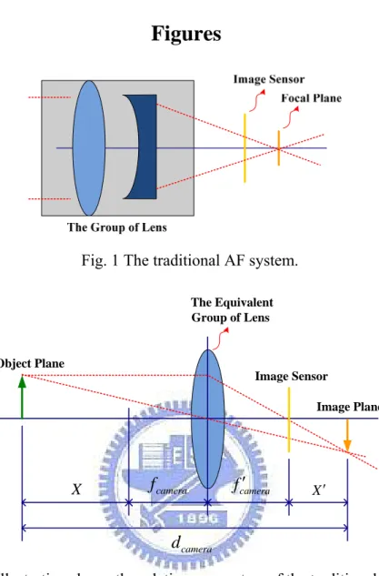
Fig. 1 The traditional AF system. ... 43
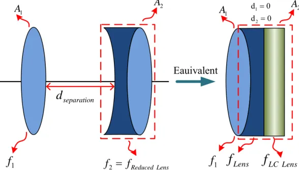
Fig. 2 The illustration shows the relative parameters of the traditional AF system. ... 43
Fig. 3 The traditional zooming system. [28] ... 43
Fig. 4 The zooming system including positive LC lens. ... 44
Fig. 5 The illustration shows the function of zooming by a positive LC lens. ... 44
Fig. 6 The zooming system including negative LC lens. ... 45
Fig. 7 The illustration shows the function of zooming by a negative LC lens. ... 45
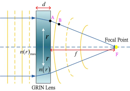
Fig. 8 The geometry corresponds to the focusing of parallel rays by a GRIN lens. ... 46
Fig. 9 The orientation model for nematic liquid crystal molecules rise from the substrate by the electric field. ... 46
Fig. 10 The relation between the applied voltage V and the maximum tilting angle φm. ... 47
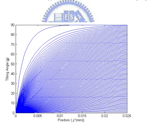
Fig. 11 The relation between the tilting angle φ and the position in coordinate z′ . ... 47
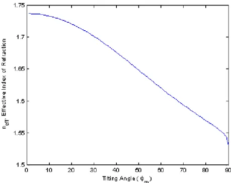
Fig. 12 The relation between the effective index of refraction neff and the maximum tilting angle φm. ... 48
Fig. 13 The effective index distribution of refraction neff
( )
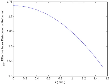
r corresponds to the maximum tilting angle φm from center to the radius r of effective aperture (φm from 0 to 90° ° ). ... 48Fig. 14 The relation between the effective index distribution of refraction neff
( )
r and the radius r of effective aperture of the LC lens with multi-ring electrodes is given the focal length 112mm. ... 49Fig. 15 The relation between the phase retardation δ
( )
r and the radius r of effective aperture of the LC lens with multi-ring electrodes lens is given the focal length 112mm. ... 49viii
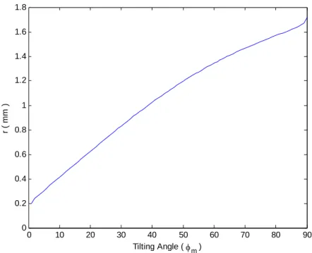
Fig. 16 The relation between the radius r of effective aperture and the maximum tilting
angle φm. ... 50
Fig. 17 The relation between the applied voltage V and the radius r of effective aperture.
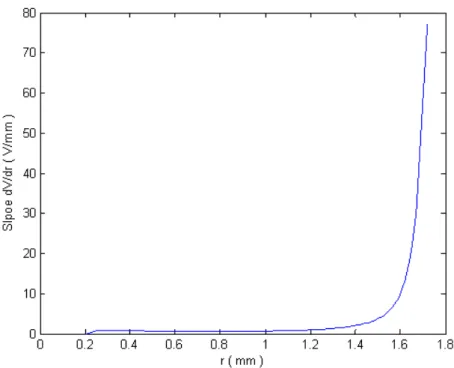
... 50 Fig. 18 The relation between the slope of V r
( )
and the radius r of effective aperture. ... 51Fig. 19 The LC lens with the number of ring electrodes from two to seven rings in different layers. ... 52 Fig. 20 The relative thicknesses and materials of the LC lens with three-ring electrodes in
different layers. ... 52 Fig. 21 The structure of the LC lens with three-ring electrodes in different layers: (a) the
upper view of the LC lens; (b) the hole-type electrode of the LC lens; (c) the first ring electrode of the LC lens; (d) the second ring electrode of the LC lens; (e) the third ring electrode of the LC lens; (f) the photo mask to expose the conducting plates of the LC lens. ... 53 Fig. 22 The software package 2dimMOSTM from Autronic-Melchers is used to simulate the
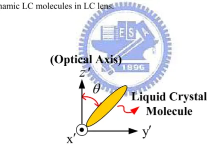
dynamic LC molecules in LC lens. ... 54 Fig. 23 The coordinate of LC molecule and tilting angle θ between the liquid crystal
molecule and optical axis z′. ... 54
Fig. 24 (a) The ellipsoid of revolution representing neff
( )
θ ; (b) propagation of theextraordinary beam obliquely through LC molecules. ... 55 Fig. 25 The effective index distribution of refraction neff
( )
r is illustrated that one is aix
Fig. 26 Compared with the index distribution of GRIN lens which the focal length is also 112mm (Ideal case) and the effective index distribution of refractive neff
( )
r of LClens (the wave length of light λ=633nm): (a) the LC lens with only single-hole electrode; (b) the LC lens with the number of ring electrodes from two to seven rings in different layers. ... 56 Fig. 27 The circular aperture of LC lens geometry illustrates the relative parameters for the
calculation of PSF. ... 57 Fig. 28 The imagery of a bar target: (a) a typical bar target used in testing optical systems
consists of alternating brightness and dark bars. If the pattern has a frequency of N lines per millimeter, then it has a period of 1 N millimeters, as indicated; (b) a plot of the brightness of (a) is a square wave. ... 57 Fig. 29 The calculation of MTF by modulation is constructed by the operation of
convolution, where ⊗ is a convolution operator. ... 58 Fig. 30 As the test pattern is made finer, the contrast between the brightness and dark areas
of the image is reduced. ... 58 Fig. 31 The LC lens with the hole-type electrode that the diameter of effective aperture and
the length of square shape are 3mm and 20mm respectively in our laboratory.. ... 59 Fig. 32 By given the applied voltage form 10Vrms to 50Vrms in 5Vrms steps for the LC lens
with the hole-type electrode in our laboratory, their calculating results of effective index distribution of refractive neff( )r are shown respectively (the wave length of
light λ=633nm). ... 60 Fig. 33 By given the applied voltage form 10Vrms to 50Vrms in 5Vrms steps for the LC lens
with the hole-type electrode in our laboratory, their calculating results of irradiance distribution as the PSF are shown respectively (the wave length of light λ=633nm). ... 61
x
Fig. 34 By given the applied voltage form 10Vrms to 50Vrms in 5Vrms steps for the LC lens with the hole-type electrode in our laboratory, their calculating results of MTF are shown respectively (the wave length of light λ=633nm). ... 62 Fig. 35 The calculating results of irradiance distribution as the PSF of the LC lens with the
number of ring electrodes from two to seven rings in different layers where its observation plane has the highest peak of relative intensity are shown respectively (the wave length of light λ=633nm). ... 63 Fig. 36 The calculating results of MTF for the LC lens with the number of ring electrodes
from two to seven rings in different layers where its observation plane has the highest peak of relative intensity are shown respectively (the wave length of light λ=633nm). ... 64 Fig. 37 As the calculating results of MTF where its observation plane has the highest peak
of relative intensity, the MTF corresponding to 5Lp mm from the LC lens with the number of ring electrodes from two to seven rings in different layers are illustrated (the wave length of light λ=633nm). ... 65 Fig. 38 As the calculating results of MTF where its observation plane has the highest peak
of relative intensity, the MTF corresponding to 7Lp mm from the LC lens with the number of ring electrodes from two to seven rings in different layers are illustrated (the wave length of light λ=633nm). ... 65
xi
Table Titles
Table 1: The specifications of two general lenses for cameras in cell phones. [28] ... 66 Table 2: The lens-group-moving distance is calculated along the optical axis based on the theory of traditional AF system. ... 66 Table 3: The specifications of general optical glass lens with diameter 3mm. ... 66 Table 4: The zooming system includes a positive LC lens for cameras in cell phones with the function of zooming. ... 67
Table 5: With the same specifications of Form 1x to 2x
EFL EFL
f f and f in Table 4, the 1
movement saved by LC lens and the separation dseparation for traditional zooming system are
calculated. ... 67 Table 6: The zooming system includes a negative LC lens for cameras in cell phones with the function of zooming. ... 68
Table 7: With the same specifications of Form 1x to 2x
EFL EFL
f f and f in Table 6, the 2 movement saved by LC lens and the separation dseparation for traditional zooming system are
calculated. ... 68 Table 8: The relative parameters for the design of the LC lens with multi-ring electrodes in different layers and the specifications of LC are shown. ... 69 Table 9: The numerical values of slope dV dr form the calculating result in Fig. 18 and
its corresponding position of radius are listed to be the reference for the design of the LC lens with multi-ring electrodes. ... 69
xii
Table 10: According to the redistributions by the slope range considered, the numerical values of the position of radius and the width of electrode in Table 9 are separated into 12
groups. ... 72
Table 11: The design for the widths of the LC lens with two-ring electrodes is shown. ... 73
Table 12: The design for the widths of the LC lens with three-ring electrodes is shown. ... 73
Table 13: The design for the widths of the LC lens with four-ring electrodes is shown. ... 74
Table 14: The design for the widths of the LC lens with five-ring electrodes is shown. ... 74
Table 15: The design for the widths of the LC lens with six-ring electrodes is shown. ... 75
Table 16: The design for the widths of the LC lens with seven-ring electrodes is shown. ... 75
Table 17: The design for the applied voltage of the LC lens with two-ring electrodes in different layers is shown. ... 76
Table 18: The design for the applied voltage of the LC lens with three-ring electrodes in different layers is shown. ... 76
Table 19: The design for the applied voltage of the LC lens with four-ring electrodes in different layers is shown. ... 77
Table 20: The design for the applied voltage of the LC lens with five-ring electrodes in different layers is shown. ... 77
Table 21: The design for the applied voltage of the LC lens with six-ring electrodes in different layers is shown. ... 78
Table 22: The design for the applied voltage of the LC lens with seven-ring electrodes in different layers is shown. ... 78
xiii
Table 23: The width of each ring electrode and its applied voltage Vmulti layer- of the LC
lens with two-ring electrodes in different layers for simulation are reorganized and determined. ... 79
Table 24: The width of each ring electrode and its applied voltage Vmulti layer- of the LC
lens with three-ring electrodes in different layers for simulation are reorganized and determined. ... 79
Table 25: The width of each ring electrode and its applied voltage Vmulti layer- of the LC
lens with four-ring electrodes in different layers for simulation are reorganized and determined. ... 80
Table26: The width of each ring electrode and its applied voltage Vmulti layer- of the LC
lens with five-ring electrodes in different layers for simulation are reorganized and determined. ... 80
Table 27: The width of each ring electrode and its applied voltage Vmulti layer- of the LC
lens with six-ring electrodes in different layers for simulation are reorganized and determined. ... 81
Table 28: The width of each ring electrode and its applied voltage Vmulti layer- of the LC
lens with seven-ring electrodes in different layers for simulation are reorganized and determined. ... 81 Table 29: The relative parameters for the design of the LC lens with the hole-type electrode and the specifications of LC in our laboratory are shown. ... 82
- 1 -
1 Introduction
Digital cameras in mobile phones are currently inexpensive with satisfactory image definition as compared to conventional cameras, thus increasing consumer requirements and rapid development of camera phone technology. There are three image functions dominating the performance of a digital phone camera. These functions are implemented by the modules of auto-focusing (AF), zooming and auto-white-balance (AWB) [1-2]. Among them, the auto-focusing and zooming functions are the most fundamental one and gradually regarded indispensable by the consumers purchasing a cell phone [3]. Nowadays, a small-sized optical lens module being magnetically actuated is most widely adopted in cell phones thanks to merits of low cost and fast response. However, the implementation of auto-focusing and zooming are realized by traditional motions of some lenses in the optical lens module, which in results, requires certain thickness of the module, leading to the great difficulty to be implemented in the phone cameras. To remedy the problem, a novel LC lens with multi-ring electrodes are designed and optimized, which replaces the moving lens in the aforementioned optical module, and expected to be implemented into the phone cameras. The newly-designed LC lens would be capable of simultaneously achieve short focal length, varying focal length and maintain satisfactory imaging quality.
Lenses are usually made of optical glass owing to that glass has large refractive index and is transparent. In many applications, variable-focus lenses are usually desired. A traditional variable-focus lens is composed of several pieces of glass lenses, and the focus changing is accomplished by mechanical movement of the individual lenses in it. Like glass material, liquid crystal (LC) materials also have large refractive indexes and are transparent, but their electrical and optical properties are anisotropic, and they are widely used to fabricate electro-optic devices. Many applications of LC to optical devices such as optical waveguides,
- 2 -
optical switches, and light deflection devices have been reported. Therefore the optical lens could be realized by the LC materials, and it was proposed over 20 years ago [4]. Compared with the variable-focus lenses made by glass lenses for cameras in cell phones, the LC lens is compact, lightweight, and inexpensive. The advantage of LC Lens is that one can apply non-uniform electric field distribution between the electrodes to tune the focal length. Since the electric field distribution in the LC is non-uniform, therefore how to design the electrode structures and apply the voltage to form the appropriate electric field distribution are very important tasks to control the focal length.
The LC lens has been published since 1979 by Susumu Sato [4]. Susumu Sato uses a thin layer of LC that one is sandwiched between two glass substrates. The structure could change the focal length by electrically controllable method. According to the method, the optical effective could be the same as the optical element of plano-convex lens or plano-concave lens. Since the LC lens was published in 1979, the research of LC lens was conducted and studied widely, and it was enabled many applications such as focal length controllable, the magnification of image, optical axis tunable etc. The researches of Susumu Sato contain the design of focal length controlled by different structures, the solvent of design issues and the design of optical axis tunable. In 1997, Susumu Sato et al. [5] have present a new method to improve the spherical aberration of LC lens by using nematic liquid crystal and an elliptically-patterned electrode structure to observe its interference patterns by a microscope of charge-coupled device (CCD). In 2002, Susumu Sato et al. [6-7] have propose a LC lens with a simple cell structure which it was prepared using a hole-patterned electrode and an intermediate insulating layer, but the design made it difficult for disclination lines to appear. A LC lens with a spherical electrode was proposed by Susumu Sato et al. in 2002 [8-10]. With the transparent indium tin oxide (ITO) film being coated on the spherical surface of a plano-convex glass lens that was placed on a planar LC cell to make the result as a traditional
- 3 -
glass lens does. As the similar structure of LC lens was also proposed by S.-T. Wu et al. in 2004 [11-12]. A tunable focus with spherical lens or spherical glass shell and inhomogeneous electric field over a homogeneous LC layer to fill polymer in the sag region, the focal length was gradually drawn near from infinity to ~96 cm by increasing the applied voltage. A LC lens of two LC layers was proposed to increase the lens focusing power by Susumu Sato et al. in 2004 [13-14]. Its focusing power is electrically tunable and is much larger than two times that of the single-layer LC lens. A cylindrical lens was proposed using two planar substrates and a homogeneous LC layer by S.-T. Wu et al. in 2004 [15]. Based on this design, it was easy to fabricate a cylindrical lens with large aperture size with the tunable range from infinity to 10 cm and the switching time less than 100 ms attributed to the thin cell gap. An adaptive lens using electrically induced LC/monomer concentration redistribution was proposed by S.-T. Wu et al. in 2006 [16]. Application of the LC/monomer mixture electric field causes the LC molecules to diffuse towards the high field region and the liquid monomer towards the low field region. Compared with a conventional LC lens, the tunable focus lens has advantage in small astigmatism and without light scattering, but its response time was slower. A negative LC lens was realized using a two-voltage-driving system by Susumu Sato et al. in 2005 [17-18]. After the negative LC lens, a LC lens with focal length variable from negative to positive was proposed by Susumu Sato et al. in 2006 [19]. There were three electrodes in the LC cell, and the lens was driven by two voltages that produce a spatially non-uniform and symmetrical electric field in the LC layer. A new method was proposed to drive a LC lens with no defects occurring by Susumu Sato et al. in 2003 [20-23]. A voltage difference remains between the two ends of one of the lens’ electrodes for a short time and an in-plane electric field from in the LC to prevent the defect of disclination line. A LC lens with focus movable off as well as along the axis was realized by Susumu Sato et al. in 2003 [24-25]. There were two electrodes in the cell: one with a hole and another with resistance and subelectrodes. The focus was adjusted along the axis by the applied
- 4 -
voltage across the two electrodes, and it was also moved off the axis by the voltage across the subelectrodes. A LC lens with focus movable in the focal plane was proposed by Susumu Sato et al. in 2005 [26]. One electrode with hole in the center was divided into four subelectrodes. By applying different potentials to the subelectrodes, a desired asymmetrical phase transformation is formed and off-axis movement of the focus take place. According to the references, the above-mentioned results of past research may apply to cameras in cell phones with LC lens.
According to the advantages and results of past research, the most worthy application of LC lens is used for the camera lens of cell phone in present. Nowadays, the most popular functions of the camera in cell phone are the auto-focusing (AF) and zooming system. If the LC lens could replace some moving lenses of cameras in cell phones, it would not only to reduce the thickness, weight and cost, but also easily make the camera in cell phones having the AF system and the function of zooming at the same time. The LC lens in this study is designed of non-uniform width multiple rings in order to render the focal length required by general phone camera --- which is about 10cm, and simultaneously fine-tune imaging quality via multiple rings. In the next step, to assess the imaging quality of the LC lens quantitatively, the methods are developed based on point spread function (PSF) and modulation transfer function (MTF). According to the above-mentioned assessment methods, the study is further to optimize the LC lens with multi-ring electrodes in different widths and layers. In this way, the newly-designed LC with multiple-ring electrodes performs better than the traditional hole-type LC lens [6-7] in terms of PSFs and MTFs.
- 5 -
2 A Liquid Crystal Lens Applied to Cell Phones
Nowadays, the most popular functions of the camera in cell phone are the auto-focusing (AF) and zooming system. The implementation of auto-focusing and zooming are realized by traditional motions of some lenses in the optical lens module, which in results, requires certain thickness of the module, leading to the great difficulty to be implemented in the phone cameras. As the requirements, if the LC lens could replace some moving lenses of cameras in cell phones, it would not only to reduce the thickness, weight and cost, but also easily make the camera in cell phones having the AF system and the function of zooming at the same time.
2.1 Function of Auto Focusing
2.1.1 The Traditional Auto Focusing System
The auto-focusing (AF) systems usually rely on one actuator and many groups of lens to achieve correct focus. The traditional AF system is shown in Fig. 1. The operation of AF is realized by adjusting the axial positions of a certain group of lens, X ′ , in order to adjust the focal plane to be located in the image sensor. In Fig. 2, the distance X ′ is derived as followed, [27]
,
camera camera camera
d = − −X f + f′ +X′ (1)
where dcamera, f ′camera( fcamera), X and X ′ are the distance of shot, the focal length of camera, the distance of object (general around 50 times the focal length of camera) and the distance of image, respectively. From the Newtonian formula X′⋅ = −X
(
fcamera′)
2, Eq. (1) is reorganized as followed,(
)
2( )
22 ,
camera camera camera
- 6 -
( ) (
2)
(
)
22 camera camera camera 0.
X′ + ⋅ f′ −d ⋅X′+ f′ = (3)
Defining the parameter A= ⋅2 fcamera′ −dcamera, Eq. (3) is simplified and calculated as followed,
( )
2(
)
2 0, camera X′ + ⋅A X′+ f′ = (4)(
)
2 2 4 . 2 camera A A f X′ = − ± − ′ (5)The lens-group-moving distance X ′ is the difference between the focal plane with finite distance from object (dcamera) and the focal plane with infinite distance from object. As shown in Fig.2, with the finite distance from object, the group of lens moves to the object along the optical axis in distance X ′ , and the image plane is maintained in the fixed location.
2.1.2 The New Auto Focusing System including a Liquid Crystal Lens
The advantage of LC lens is that one would generate non-uniform electric field distribution between the electrodes to tune the focal length. According to the function, the traditional AF system in order to adjust the appropriate focal length, it would have to equip the actuator to drive the group of lens. As the result, the AF system for cameras in cell phones would need more thickness to move the group of lens, resulting in higher cost. Based on the reasons, if the LC lens could replace the whole traditional AF system to adjust the appropriate focal length, the actuator and many groups of lens would be reduced. In other words, the thickness and cost of AF system would be reduced for cameras in cell phones. In Table 1 [28], where are the specifications of two general lenses for cameras in cell phones. By the specifications, the lens-group-moving distance is calculated along the optical axis based on the theory of traditional AF system in Eq. (5), as shown in Table 2. As the results of calculation, if the camera in cell phones with lens 1 needs to shoot the object from 600 to 100mm, the traditional AF system has to need more thickness from 0.013 to 0.08mm to adjust the focal length; if the
- 7 -
camera in cell phones with lens 2 needs to shoot the object from 600 to 100mm, the traditional AF system has to need more thickness from 0.019 to 0.12mm to adjust the focal length. Although the distance of movement is not reduced very much if the LC lens replaces the traditional AF system, the cost of the whole traditional AF system is still reduced due to the fact that the actuator in AF system is not needed and the thickness of cell phone lens would be thinner.
2.2 Function of Zooming
2.2.1 The Traditional Zooming System
A zoom lens has a function of variable focal length. For practical photographic applications the position of the second principle plane of the lens from the film plane also must vary to keep the image on the film. The simplest and traditional zoom lens is composed of a positive and negative singlet lens. The variation in focal length is obtained by adjusting the separation of the lenses, and a sharp focus is maintained by varying the distance of the lenses from the film plane. As shown in Fig. 3 is a traditional zooming system. The focal length of the zoom lens depends on the Gullstrand equation because of the equivalent power of two airspaced lenses varied with their separation dseparation as below, [29]
1 2 separation 1 2,
F =F +F −d ⋅ ⋅F F (6)
where F , F , 1 F and 2 dseparation are the equivalent power, the power of first lens A , the 1 power of second lens A and the separate distance from first lens to second lens, respectively. 2 The distance of the lenses from the film plane depend on the variation in back focal length
2
- 8 - 1 2 1 . separation d F A F F − ⋅ ′ = (7)
Equation (7) shows how far the negative lens must be from the film plane. The positive lens must be an additional distance dseparation from the film plane as below,
1 separation 2 ,
A F′=d +A F′ (8)
where the distance of A F ′1 is called the overall length. The traditional function of zooming
corresponds to moving the negative lens to the second focal plane of the positive lens, and into coincidence with the film plane. In Fig. 3, where the results of Eq. (6), Eq. (7) and Eq. (8) as the equivalent focal length is varied from 50 to 25mm in 5mm steps. The movement of the negative lens is linear with respect to focal length. However, the positive lens requires a special cam to position it appropriately. Consequently, the traditional function of zooming works by the varied of the distance A F ′2 to determine the separation dseparation and the effective focal length of zoom lens when the focal length of positive lens (A ) and negative lens (1 A ) are all 2 fixed.
2.2.2 The New Zooming System including Liquid Crystal Lens
The characteristic of the zooming system is that one could vary the focal length in camera. A traditional zooming system is composed of several pieces of glass lenses, and the focus changing is accomplished by mechanical movement of the individual lenses in it. Therefore, if the camera in cell phones with the traditional function of zooming, the thickness and weight would be increased. In present, cameras in cell phones are required to be more lightweight and compact. As the requests, if the LC lens could replace the traditional function of zooming to vary the focal length, the LC lens will be only to apply the appropriate electric field distribution between the electrodes, and the function of zooming for cameras in cell phones
- 9 -
will be easily to realize without thickness and weight. In this study, the diameter of effective aperture for LC lens is 3mm and the variable range of focal length is from 130 to 550mm by applying the voltage from 50Vrms to 10Vrms in our laboratory. Since the focal length of LC lens is too large for the camera lens in cell phone, there has to assemble one general positive or negative lens to reduce it when the LC lens represent a negative or positive lens. In Table 3, where are the specifications of general optical glass lens with diameter 3mm. According to the above-mentioned specifications, the variation in focal length of LC lens is calculated based on the theory of traditional zooming system, and the variation makes the camera in cell phones with the function of zooming. Since the LC lens would represent a positive or negative lens in different states, the different components of its fitting lens would be also altered to result in different variations of focal length.
2.2.2.1 The Zooming System Including Positive Liquid Crystal Lens
A zooming system including a positive LC lens for cameras in cell phones is shown in Fig. 4. In order to reduce the focal length of positive LC lens for cameras in cell phones, the LC lens has to assemble one general negative lens. Since the LC lens is the structure of two parallel ITO electrodes, the general negative lens would be one optical plano-concave lens to fit the LC lens. Therefore, the focal length of positive LC lens (fLC Lens) and optical plano-concave lens
( fLens) would be reduced ( fReduced Lens) by the Gullstrand equation. After reducing the focal length of LC lens, the reduced lens is represented by the variable negative singlet lens (A ). 2 Because of the simplest zooming system is composed of a positive and negative singlet lens, the zooming system including positive LC lens is completed by adding one general positive singlet lens (A ). The variable focal length of LC lens from 1 fLC Lens1x to fLC Lens2x is determined
by the variable effective focal length of zooming system from 1x EFL
f to fEFL2x based on the Gullstrand equation. The relative formulas for zooming system including positive LC lens are
- 10 -
derived as followed where the reduced lens in it is equivalent a variable negative singlet lens. According to the design of zooming system including positive LC lens, the focal length of reduced lens that is varied before ( 1x
Reduced Lens
f ) has to calculate in priori as below,
1x 1x 1x
1 ,
Reduced Lens LC Lens Lens LC Lens Lens
F =F +F − ⋅d F ⋅F (9)
where 1x Reduced Lens
F , FLC Lens1x and FLens are the power of reduced lens that the focal length of
positive LC lens is varied before, the power of positive LC lens that the focal length is varied before and the power of optical plano-concave lens, respectively. In Eq. (9), the distance d is 1 separated from LC lens to optical plano-concave lens and it is designed as two lens close together (d1= ). After the calculation of 0 fReduced Lens1x , the focal length of general positive
singlet lens ( f ) is calculated with that the effective focal length of zooming system is 1 fEFL1x as
below,
1x 1x 1x
1 2 1 ,
EFL Reduced Lens Reduced Lens
F =F +F − ⋅ ⋅d F F (10)
where 1x EFL
F and F are the power of zoom lens that the effective focal length is varied before, 1 the power of general positive singlet lens, respectively. In Eq. (10), the distance d is 2 separated from reduced lens to general positive singlet lens and it is designed as two lens close together (d2 = ). As the conditions in Eq. (10) that the focal length of general positive singlet 0 lens is fixed and the focal length of reduced lens is variable, the focal length of positive LC lens is varied with the effective focal length of zooming system varied from 1x
EFL
f to fEFL2x .
Based on the conditions, the varied focal length of reduced lens ( 2x Reduced Lens
f ) is calculated as below,
2x 2x
1 ,
EFL Reduced Lens
- 11 - where 2x
EFL
F and FReduced Lens2x are the power of zoom lens that the effective focal length is varied and the power of reduced lens that the focal length of positive LC lens is varied, respectively. Therefore, the varied focal length of the positive LC lens ( 2x
LC Lens
f ) is calculated by the varied focal length of the reduced lens and the focal length of optical plano-concave lens as below,
2x 2x ,
Reduced Lens LC Lens Lens
F =F +F (12)
where 2x LC Lens
F is the power of positive LC lens that the focal length is varied. Consequently,
the zooming system including positive LC lens works by the varied distance A F ′2 that the
distance is between the reduced lens and the film plane as below,
2 1 . EFL A F F ′ = (13)
With the effective focal length of zooming system varied from 1x EFL
f to fEFL2x , the distance
2
A F ′ is also varied at the same time.
As the above-mentioned deriving, the varied effective focal length of zooming system from
1x EFL
f to fEFL2x has to work by the focal length of positive LC lens varied from fLC Lens1x to
2x LC Lens
f . According to the design of zooming system including positive LC lens, the movement
2
A F ′ and the separation dseparation for the traditional zooming system are reduced for cameras
in cell phones. Based on the above-mentioned design, the results of zooming system including positive LC lens for cameras in cell phones with the function of zooming are calculated. The specifications for calculating and its results are shown in Table 4 and Fig. 5, where
1x 2x
- 12 -
length of zoom lens, the focal length of optical plano-concave lens, the focal length of general positive singlet lens and the variation in focal length of positive LC lens, respectively. Use the same specifications of reduced lens that one represents a variable negative singlet lens to replace the negative singlet lens in traditional zooming system. In other words, the focal length
2
f is replaced by the focal length fReduced Lens. By the replaced and the same specifications of
1x 2x
Form fEFL to fEFL and f in Table 4, the movement saved by LC lens and the separation 1
separation
d for traditional zooming system are calculated, as shown in Table 5. Compared with
the results of calculation in Table 4 and Table 5, the zooming system including positive LC lens is proved more lightweight and compact than traditional one applied to cameras in cell phones in the same zooming range from 1x
EFL
f to fEFL2x .
2.2.2.2 The Zooming System Including Negative Liquid Crystal Lens
A zooming system including a negative LC lens for cameras in cell phones is shown in Fig. 6. In order to reduce the focal length of negative LC lens for cameras in cell phones, the LC lens has to assemble one general positive lens. Since the LC lens is the structure of two parallel ITO electrodes, the general positive lens would be one optical plano-convex lens to fit the LC lens. Therefore, the focal length of negative LC lens ( fLC Lens) and optical plano-convex lens ( fLens)
would be reduced (fReduced Lens) by the Gullstrand equation. After reducing the focal length of LC lens, the reduced lens is represented the variable positive singlet lens (A ). By the similar 1 way to vary the focal length of LC lens in section 2.2.2.1, the zooming system including negative LC lens is completed by adding one general negative singlet lens (A ). The relative 2 formulas for zooming system including negative LC lens are derived as followed where the reduced lens in it is equivalent a variable positive singlet lens. According to the design of zooming system including negative LC lens, the focal length of reduced lens that is varied
- 13 - before ( 1x
Reduced Lens
f ) also has to calculate in priori by the similar formula in Eq. (9), where
1x Reduced Lens
F , FLC Lens1x and FLens are the power of reduced lens that the focal length of negative
LC lens is varied before, the power of negative LC lens that the focal length is varied before and the power of optical plano-convex lens, respectively. In Eq. (9), d is the distance 1 separate from LC lens to optical plano-convex lens is also designed as two lens close together (d1= ). After the calculation of 0 fReduced Lens1x , the focal length of general negative singlet lens
( f ) is calculated with that the effective focal length of zooming system is 2 fEFL1x as below,
1x 1x 1x
2 2 2,
EFL Reduced Lens Reduced Lens
F =F +F − ⋅d F ⋅F (14)
where F is the power of general negative singlet lens, and the distance 2 d separated from 2 reduced lens to general negative singlet lens is also designed as two lens close together (d2 = ) 0 in Eq. (14). As the conditions in Eq. (14) that the focal length of general negative singlet lens is fixed and the focal length of reduced lens is variable, the focal length of negative LC lens is varied with the effective focal length of zooming system varied from 1x
EFL
f to fEFL2x . Based on
the conditions, the varied focal length of the reduced lens ( 2x Reduced Lens
f ) is calculated as below,
2x 2x
2,
EFL Reduced Lens
F =F +F (15)
where 2x Reduced Lens
F is the power of reduced lens that the focal length of negative LC lens is
varied. Therefore, the varied focal length of the negative LC lens ( 2x LC Lens
f ) is calculated by the varied focal length of the reduced lens and the focal length of optical plano-convex lens, as the similar formula in Eq. (12), where 2x
LC Lens
F is the power of negative LC lens that the focal length is varied. Consequently, the zooming system including negative LC lens works by the
- 14 -
varied distance A F ′2 that the distance is between the reduced lens and the film plane as also
shown in Eq. (13). With the effective focal length of zooming system varied from 1x EFL
f to
2x EFL
f , the distance A F ′2 is also varied at the same time.
As the above-mentioned deriving, the varied effective focal length of zooming system from
1x EFL
f to fEFL2x has to work by the focal length of positive LC lens varied from fLC Lens1x to
2x LC Lens
f . According to the design of zooming system including negative LC lens, the movement
2
A F ′ and the separation dseparation for the traditional zooming system are reduced for cameras
in cell phones. Based on the above-mentioned design, the results of zooming system including negative LC lens for cameras in cell phones with the function of zooming are calculated. The specifications for calculating and its results are shown in Table 6 and Fig. 7, where
1x 2x
Form fEFL to fEFL, fLens, f and 2 From fLC Lens1x to fLC Lens2x are the variation in effective focal
length of zoom lens, the focal length of optical plano-convex lens, the focal length of general negative singlet lens and the variation in focal length of negative LC lens, respectively. Use the same specifications of reduced lens that one represents a variable positive singlet lens to replace the positive singlet lens in traditional zooming system. In other words, the focal length
1
f is replaced by the focal length fReduced Lens. By the replaced and the same specifications of
1x 2x
Form fEFL to fEFL and f in Table 6, the movement saved by LC lens and the separation 2
separation
d for traditional zooming system are calculated, as shown in Table 7. Compared with
the results of calculation in Table 6 and Table 7, the zooming system including negative LC lens is also proved more lightweight and compact than traditional one applied to cameras in cell phones in the same zooming range from 1x
EFL
- 15 -
3. Designing the Liquid Crystal Lens with Multi-ring Electrodes
As compared to conventional cameras, the lens module in phone cameras particularly requires shorter focal length and larger aperture. The currently available LC lenses, however, fails to provide both the above capabilities. To remedy the problem, the method to design non-uniform width multiple rings in order to render the focal length and the aperture required by general phone camera is developed.
3.1 Theory of Gradient Index Lens
An ordinary homogeneous lens has two physical features that contribute to the manner in which it reconfigures a wavefront: the difference between its index of refraction and that of the surrounding medium, and the curvature of its interfaces. As the known formula, v=c n,
where c, n and v are the velocity in vacuum, index of refraction and the velocity in medium, respectively. As the light propagating through an inhomogeneous medium, wavefronts essentially slow down in optically dense regions and speed up in less dense region. In principle, the lens from some inhomogeneous material is such as the gradient in the index of refraction; such the device is called the GRIN Lens (GRadient INdex Lens) [30]. Consider the device as shown in Fig. 8, for simplicity, assume f > . The GRIN Lens is a flat disk of r glass that has been treated so that the lens has an index n r
( )
that drops off radially in someas yet undetermined fashion from a maximum value of n r
( )
max on the optical axis. A raythat traverses the lens on the optical axis passes along an optical path length (OPL) of
(
OPL)
( )
maxaxis =n r ⋅d, whereas for a ray traversing at a height r , overlooking the slight
bending of its path,
(
OPL)
( )
r ≈n r ⋅d. Since a planer wavefront must bend into a spherical
- 16 -
(
OPL)
r+AB≅(
OPL)
axis, (16) and( )
( )
max . n r ⋅ +d AB≅n r ⋅ (17) d But 2 2 AF ≈ r + f ; moreover, AB= AF− and so f( ) ( )
max r2 f2 f . n r n r d + − = − (18)According to the square roots that via the Binomial Theorem (
2 2 2 1 1 2 r r f f f ⎡ ⎛ ⎞ ⎤ + ≈ ⎢ + ⎜ ⎟ ⎥ ⎢ ⎝ ⎠ ⎥ ⎣ ⎦ ), Eq. (18) is simplified as
( ) ( )
max 2 . 2 r n r n r fd = − (19)As the result, if the index of refraction drops off parabolically from its high along the central axis, the GRIN plate would focus a collimated beam at point F and serve as a positive lens. Moreover, Eq. (20) is simplified from Eq. (19) as below,
( )
( )
( )
2 2 max . 2 2 r r f d n r d n r n r = = ⋅ Δ ⎡ ⎤ ⋅⎣ − ⎦ (20)From Eq. (20), the focal length is varied by the thickness of the lens (d) and the difference in
- 17 -
3.2 Developing the Design for the Liquid Crystal Lens with Multi-ring Electrodes
In order to render better performance from the LC lens, designs of the electrodes and relative voltage to form the appropriate distribution of non-uniform electric field are very important tasks. The effective index distribution of refraction of LC lens is yielded with the non-uniform electric field by the properties of dielectric behavior. Effects due to conductivity of the LC have been neglected. In this study, the nematic liquid crystal is used to be the LC material of LC lens with multi-ring electrodes. By the orientation of nematic liquid crystals in an electric field between two electrode plates as shown in Fig. 9, the tilting angle of LC molecules in LC layer of the LC lens is calculated by Eq. (21) and Eq. (22) as below, [31]
2 2 2 2 2 0 (1 sin )(1 sin ) 2 , (1 sin )(sin sin )
m m o m V d V φ κ φ γ φ φ π κ φ φ φ + + = + −
∫
(21) and 2 2 2 2 0 2 2 2 2 0 (1 sin )(1 sin ) sin sin , 2 (1 sin )(1 sin ) sin sin m m m m m d d z d φ φ κ φ γ φ φ φ φ κ φ γ φ φ φ φ + + − ′ = ⋅ + + −∫
∫
(22)where V , V , o φ, φm, z′ and d are the applied voltage, the threshold voltage, the tilting
angle of LC molecule, the maximum tilting angle at the center of LC layer, the coordinate in the direction of optical axis and the thickness of LC layer, respectively. The parameters of V , o κ and γ are represented as Eq. (23), Eq. (24) and Eq. (25),
(
)
1 2 11 0 , o k V π ε ε ε⊥ ⎛ ⎞ = ⎜⎜ ⎟⎟ − ⎝ & ⎠ (23) , ε ε γ ε ⊥ ⊥ − = & (24)- 18 - and 33 11 11 , k k k κ = − (25)
where ε&, ε⊥, K11 and K33 are the relative dielectric permittivity parallel to the director of
molecules, the relative dielectric permittivity perpendicular to the director of molecules, the elastic curvature constants of splay and the elastic curvature constants of bend, respectively. The maximum tilting angle φm is determined corresponding to an applied voltage V from
Eq. (21). The tilting angle φ is a function of coordinate z′ from Eq. (22), φ
( )
z′ assuminga maximum tilting angle value φm at z′ =d 2 and being 0 at the boundaries (z′=0). In this
study, the relative parameters of nematic LC are shown in Table 8. With the parameters and assuming the range of φm from 0 to 90° ° , the relations of function V
( )
φm form Eq. (21)and φ
( )
z′ from Eq. (22) by given the range of φm are calculated as shown in Fig. 10 andFig. 11. The calculations assume that the orientation of nematic liquid crystal in the distance from 0 to d 2 and from d to d 2 of the LC layer is symmetric. According to the
assumption, the calculating results only present the range from 0 to d 2 of the LC layer to
analyze. In Fig. 10, the maximum tilting angle φm is determined by its corresponding applied
voltage. In Fig. 11, each curve of function φ
( )
z′ is represented its corresponding maximumtilting angle φm from 0 to 90° °, and the curve is also shown its distribution of tilting angle
φ at any position in the coordinate of optical axis (from 0 to d 2). According to the
calculating result from Eq. (22), the index refraction is calculated by each tilting angle φ which results from each curve of function φ
( )
z′ as below, [32]( )
2 2 2 2 , sin cos o e eff e o n n n n n φ φ φ = + (26)- 19 -
crystal in this study, respectively. As the results of calculation from each tilting angle φ with the parameters of ne and no, the effective index of refraction (neff
( )
r ) is calculated by themethod of integration. According to the calculation by the method of integration in Eq. (26), the effective index of refraction neff
( )
r from each maximum tilting angle φm(from 0 to 90° °) with its distribution of tilting angle φ is calculated, as shown in Fig. 12. Since the effective index distribution of refraction (neff
( )
r ) at the center of the LC lens withstructure of hole-type in our laboratory is not similar to the index distribution of GRIN lens, the improvement of the design for the LC lens with multi-ring electrodes is that the effective index distribution of refraction is as far as possible to design as GRIN lens. The effective focal length of the LC lens with structure of hole-type in our laboratory is about 112mm by given the voltage 50Vrms which the diameter of effective aperture and the length of square shape are 3mm and 20mm respectively. In order to improve the LC lens with structure of hole-type in our laboratory, the LC lens with multi-ring electrodes is also designed with the same specifications of focal length and diameter of effective aperture. Based on the principle of the design for the LC lens with multi-ring electrodes, the above-mentioned calculations for effective index of refraction neff
( )
r is used to represent the effective index distribution ofrefraction that the distribution is according to the maximum tilting angle φm from center to the radius of effective aperture (from 0 to 90° °) as shown in Fig. 13. With the effective index distribution of refraction neff
( )
r and given the required focal length, the radius of effectiveaperture of the LC lens with multi-ring electrodes is determined by the theory of GRIN lens as below,
2 2
0 0
, 2 ( ) 2 [ (d (0, )) d( ( , )) ]
eff eff eff
r r
f
d n r n z dz n r z dz
= =
- 20 -
where r and d are the variable radius of LC lens and the thickness of LC layer,
respectively. The effective index distribution of refraction neff
( )
r is represented that eacheffective index of refraction neff
( )
r is distributed at the radius of effective aperture from −rto r of the LC lens with multi-ring electrodes. For the design of the distribution of
maximum tilting angle φm is from 0 to 90° ° at the radius of effective aperture from center to r and from 90 to 0° ° at the radius of effective aperture from −r to center. In Eq. (27),
the difference in effective index distribution of refraction (Δneff( )r ) of the LC lens with
multi-ring electrodes means that the difference between the integration of the effective index of refraction neff
( )
r at center and at the radius of effective aperture r. According to Eq. (27),the effective index distribution of refraction neff
( )
r would only represented a function of theradius r as given the required focal length f of the LC lens with multi-ring electrodes.
Since the design of the LC Lens with multi-ring electrodes assumes circularly symmetry, the effective index distribution of refraction neff
( )
r from the radius of effective aperture −r to0 and from the radius of effective aperture 0 to r is also symmetric for perfect design. With
the assuming of symmetry, the results of calculation only present the radius of effective aperture from 0 to r of the LC lens with multi-ring electrodes to analyze. As the
above-mentioned calculations for effective index distribution of refraction neff
( )
r and thesymmetrical assumption, the effective index distribution of refraction neff
( )
r of the LC lenswith multi-ring electrodes related to its radius of effective aperture r is calculated by Eq. (27)
as given the focal length f =112mm, the calculating results as shown in Fig. 14. By the effective index distribution of refraction neff
( )
r of the LC lens with multi-ring electrodes,- 21 -
(
)
0 0 min
2 2
( )r π neff( )r d = π d(neff( , ))r z dz d(neff( , ))r z dz .
δ
λ λ ⎡ ′ ′ ′ ′ ⎤
= ⋅ Δ ⋅ ⋅⎢ − ⎥
⎣
∫
∫
⎦ (28)As the calculating results in Fig. 14, the phase retardation δ of the LC lens with multi-ring electrodes is calculated without the multiplication of 2π λ by Eq. (28), as shown in Fig. 15. Based on the calculating results of the effective index distribution of refraction neff
( )
r andthe phase retardation δ( )r for the LC lens with multi-ring electrodes as shown in Fig. 12 and
Fig. 14 respectively, each maximum tilting angle φm is corresponding to its effective index of refraction neff
( )
r , and the effective index of refraction neff( )
r is corresponding to itsradius of effective aperture r. According to the relations of calculating result, the distribution
of maximum tilting angle φm from 0 to 90° ° is related to the radius of effective aperture r,
as the function of φm
( )
r shown in Fig. 16. Since the effective index distribution ofrefraction neff
( )
r of the LC lens with multi-ring electrodes is not distinct variation fromcenter to r=0.2mm in Fig. 14, the maximum tilting angle φm at the radius of effective
aperture from center to r=0.2mm is designed as 0° , and it also makes sure that the
effective index of refraction neff
( )
r at center is the maximum. According to the results offunction V
( )
φm form Eq. (21) as shown in Fig. 10 and the above-mentioned results offunction φm
( )
r as shown in Fig. 16 respectively, the applied voltage V is related to theradius of effective aperture r, as the function of V r
( )
shown in Fig. 17. Finally the designprinciple of the LC lens with multi-ring electrodes is based on the slope of V r
( )
(denotedby dV dr) to determine each width of ring electrodes in the effective aperture, as shown in
Fig. 18.
According to the calculating results in Fig. 18, the numerical values of slope dV dr are
- 22 -
where the No. of position, the position of radius, the width of electrode, the range of slope (dV dr) and the difference in range of slope (Δ
(
dV dr)
) are shown in it respectively.According to the numerical values in Table 9, the numerical values of Δ
(
dV dr)
with itscorresponding position of radius are separated into some regularity in the varied range of slope. As the results in Table 9 obvious that the slope range considered are separated into some ranges with the corresponding position of radius such as the range from 0.25 to 0.3, from 0.2 to 0.25, from 0.15 to 0.2, from 0.1 to 0.15, from 0 to 0.05, from 0.01 to 0.05, from 0 to 0.01, from 0.01 to 0.02, from 0.02 to 0.03 and from 0.01 to 0.02, respectively. According to the separated ranges, some numerical values of Δ
(
dV dr)
with the corresponding positionof radius are distributed to its slope range considered. With the redistributions by the slope range considered, the numerical values of the position of radius and the width of electrode in Table 9 are separated into 12 groups as shown in Table 10. As the results in Table 10, the numerical results of the difference in varied range of slope are calculated, and it is used to design the width of electrodes for LC lens with multi-ring electrodes. Moreover, the design principle of each width of electrodes is according to the same numerical value of difference in varied range of slope designed as one electrode, and it is still keeping the theorem that the width of electrode is increased with the decrease of difference in range of slope Δ
(
dV dr)
.Since the diameter of effective aperture and the length of square shape have been determined in this study, the width of side electrode or the hole-type electrode of LC lens with multi-ring electrodes also has determined that one is 8500μm. Since the maximum tilting angle φm at
the radius of effective aperture from center to r=0.2mm has been designed as 0° , the
width of central electrode or the first ring of LC lens with multi-ring electrodes also has determined that one is 0.2mm by given 0Vrms. Based on the above design of width for the hole-type and the first ring electrodes, the LC lens with multi-ring electrodes has been owned
- 23 -
first ring initially. As the above-mentioned designs, the LC lens with multi-ring electrodes in this study would like to design the number of ring electrodes from two to seven rings, as shown in Table 11-16, where are shown the widths of each ring with its corresponding position of radius and its corresponding range of group with the slope range considered respectively. As the results of design, the applied voltage V to each electrode of the LC lens
with multi-ring electrodes is corresponding to its position of radius by the function of V r
( )
,as shown in Fig. 17. At the moment of applied voltage V r
( )
, the results are given betweentwo electrode plates with the thickness d of LC layer, and the electric field ELC
( )
rbetween two electrode plates is yielded in the LC layer.
Since the multi-ring electrodes of LC lens are designed in the same layer, the ring electrodes would not be complete in order to put the conducting wire in the same layer. As the design of LC lens with multi-ring electrodes, the defect of performance is yielded cause of that the ring electrodes are not complete to affect the distribution of electric field. In order to improve the defect of performance, the multi-ring electrodes of LC lens are designed in different layers in this study, as shown in Fig. 19, where the LC lens with the number of ring electrodes from two to seven rings are shown respectively. The widths of ring electrode for each LC lens with the number of ring electrodes from two to seven rings are shown from Table 11 to Table 16, respectively. In order to show the thicknesses and materials of the LC lens with multi-ring electrodes in different layers simply in Fig. 19, the LC lens with three-ring electrodes in different layers is represented to illustrate the relative thicknesses and materials, as shown in Fig. 20, where the thicknesses and materials are also shown in Table 8. In the processes of fabrication for the LC lens with multi-ring electrodes in different layers, in order to show it simply, the LC lens with three-ring electrodes in different layers is also represented to illustrate the relative size of the conducting wire, the conducting plate and the
- 24 -
photo mask, as shown in Fig. 21, where the upper view of the LC lens with three-ring electrodes in different layers is shown in Fig. 21(a). The hole-type electrode, the first ring electrode, the second ring electrode and the third ring electrode of the LC lens with three-ring electrodes in different layers are shown in Fig. 21(b), Fig. 21 (c), Fig. 21(d) and Fig. 21(e), respectively. As shown in Fig. 21, the each width of conducting wire, the each long side of conducting plate and the each short side of conducting plate are 40μm, 5mm and 2mm, respectively, and all materials are also ITO. In the processes of fabrication for the LC lens with multi-ring electrodes in different layers, the photo mask in Fig. 21(f) is used to expose the conducting plates where the size is the same with conducting plates. By the simply way to explain the method how to expose the conducting plates, the LC lens with three-ring electrodes in different layers is used to represent the process. According to the structure of LC lens with three-ring electrodes in different layers in Fig. 21(a) and by the photo mask in Fig. 21(f), since the four conducting plates are designed at the side of LC lens respectively, in order to expose the four conducting plates that the time for etching by the photo mask are different according to the distance of thickness from the most upper isolation layer to its conducting plate.
As the design of structure for LC lens with multi-ring electrodes in different layers, the thickness between two electrode plates that is the distance from bottom to top electrode are altered with the top ring electrode in different layers. By the alternation of thickness between two electrode plates, the numerical values of applied voltage VSingle layer- from the function of
( )
V r also have to modify at the same time. According to the numerical values of applied
voltage VSingle layer- , the electric field as the function of r is calculated,