0040-6090/02/$ - see front matter䊚 2002 Elsevier Science B.V. All rights reserved. PII: S 0 0 4 0 - 6 0 9 0 Ž 0 1 . 0 1 6 3 0 - 3
Application of inverse problem algorithm for temperature uniformity in
rapid thermal processing
Senpuu Lin *, Hsin-Sen Chu
a, b,1Department of Mechanical Engineering, National Lien Ho Institute of Technology, Miaoli 360, Taiwan, ROC
a
Department of Mechanical Engineering, National Chiao Tung University, Hsinchu 300, Taiwan, ROC
b
Received 20 April 2001; received in revised form 24 August 2001; accepted 6 September 2001
Abstract
This article presents a finite-difference-method formulation to the application of inverse problem algorithms for uniform temperature tracking of several different linear ramp-up rates in rapid thermal processing. A one-dimensional thermal model and temperature-dependent thermal properties of silicon wafers are used. The required incident-heat-flux profiles for temperature uniformity across 300-mm-diameter 0.775-mm-thick silicon wafer were intuitively evaluated. Our numerical results indicate that temperature non-uniformity occurring during the ramp increase with the ramp-up rate. Although a linear ramp-up rate of 300 8Cy
s was used and random errors did reach 3.864 8C, the temperature over the wafer was maintained within 0.665 8C of the wafer center if the incident-heat-flux profiles were dynamically controlled according to the inverse results. These temperature non-uniformities could be acceptable in the advanced rapid thermal processing system. 䊚 2002 Elsevier Science B.V. All rights reserved.
Keywords: Temperature uniformity; Rapid thermal processing; Inverse problem algorithm
1. Introduction
The semiconductor-manufacturing trend toward ultra-large-scale-integration has led to a dramatic decrease in feature size with new generation. Rapid thermal
proc-essing (RTP) is an emerging and promising technology
for microelectronic processes such as annealing, oxida-tion, chemical vapor deposition that provides numerous advantages over conventional furnace-based batch proc-essing. RTP will be indispensable to meet the process requirements of future devices. In RTP, wafers are processed one at a time in a small, cold-walled reaction chamber. The treated wafer is heated from room tem-perature to as high as 1100 8C, in a few tenths of seconds, then processed and cooled. In general, the * Corresponding author. Tel.: q886-3-7323152, ext. 25; fax: q 886-3-7371190.
E-mail addresses: [email protected](S. Lin), [email protected](H.-S. Chu).
Tel.: q886-3-5712121, ext. 55115; fax: q886-3-5727930.
1
wafer is heated by means of radiation supplied by one or more lamp banks w1x. Because of radiative heat losses from the wafer edges, uniform irradiation does not guarantee uniform radial temperature profiles. If not corrected, this radial temperature gradient is usually large enough to generate thermal stresses and produce an unacceptable variation in film thickness, which affect the processing results and wafer-to-wafer uniformity w2x. Consequently, maintaining a uniform temperature across the wafer is a process requirement w3x. Generally, the maximum temperature difference across the wafer must be maintained within 2 8C during rapid thermal proc-essing w4,5x. The stringent process uniformity and
repeatability requirements demand a continuous
improvement in wafer temperature control w6x.
Many approaches including utility of a patterned susceptor w7x and model-based control w2–4,6,8–11x have been proposed for achieving temperature unifor-mity. This paper primarily deals with the determination of incident heat flux from heaters to eliminate radial
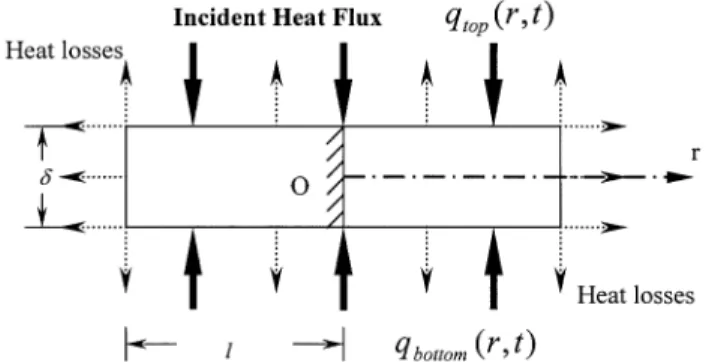
Fig. 1. Schematic representation of energy flux in a silicon wafer under two-sided incident radiation and radiant loss emitted from all surfaces.
temperature gradients across wafers w5,12–21x. Hill and Jones w13x investigated thermal uniformity with a uni-form intensity field and one in which the intensity was linearly enhanced to a maximum of 8% vertically over the last 15 mm of a 150-mm wafer. Kakoschke et al. w14x evaluated enhanced illumination intensities at wafer peripheries vertically and laterally for a compensation of edge heat losses during processing. Gyurcsik et al. w15x introduced a two-step procedure for solving an inverse optimal-lamp-contour problem to achieve tem-perature uniformity in steady state. Sorrel et al. w5x
applied power-law (first-, second- and seventh-degree)
irradiation profiles to study the increases required in perimeter irradiation to maintain a wafer at an approxi-mately uniform temperature. Norman w16x presented a technique based on linear programming for minimization of worst case error during temperature trajectory
follow-ing. Zollner et al. w17x compensated for radial tempera-¨
ture decreases using an adjustable lamp arrangement with optimized power settings calculated from wafer heat losses. Riley and Gyurcsik w18x presented a nodal analysis of wafer-edge to determine the amount of lateral heating needed to counteract edge cooling. Cho et al. w19x optimized the incident heat flux profile over a wafer by determining the heat loss profiles using Lord’s thermal model w12x, which simulates radial temperature gradients by assuming uniform temperature through the wafer thickness. Following the work of Riley and Gyurcsik w18x, Perkins et al. w20x used wafer-edge node analysis to determine the idealized intensity profiles required for maintaining thermal uniformity both during transient and steady state. Jan and Lin w21x derived a necessary and sufficient condition on the irradiation of the wafer surface for their lamp configuration design. Some of these approaches rely largely on trial-and-error, which can be quite expensive and time-consuming. Some approaches, such as Cho et al. w18x and Perkins et al. w19x, are systematic design methods for knowing whether a design satisfying given specifications exists and whether a given approach has an optimal design that satisfies given specifications. With microelectronic device specifications becoming tighter, it is imperative that the wafer temperature trajectory must be controlled precisely to meet processing requirements. Recently, computer-aided design of thermal processing based on fundamental models has become more attractive w2,3x. Balakrishnan and Edgar w2x discussed the development of temperature control algorithms for the RTP process. Janicki et al. w22x had successfully applied an inverse problem algorithm, which was implemented as a digital filter, for integrated circuit temperature estimation. Kurz
and Muller w23x presented an inverse-modeling algo-¨
rithm that is able to calculate the powers of arbitrary numbers of heaters in a crystal growth configuration in order to obtain a prescribed temperature distribution in a growing crystal. The inverse problem deals with
determining crucial parameters in analyses such as those for internal energy sources, surface heat fluxes, thermal properties, etc., and has been widely applied to many design and manufacturing problems w24,25x. We w26,27x applied a one-dimensional thermal model to study the temperature uniformity of 300-mm silicon wafers sub-jected to a uniformly distributed heat flux during RTP using the inverse-source method. It was discovered that the resulting maximum temperature differences were only 0.326 8C during RTP. In the present article, a finite-difference-method formulation to the application of inverse problem algorithms for uniform temperature tracking of several different linear ramp-up rates is studied in rapid thermal processing systems. A one-dimensional thermal model and temperature-dependent thermal properties of silicon wafers are adopted. The required incident-heat-flux profiles for temperature uni-formity across 300-mm-diameter 0.775-mm-thick silicon wafers were intuitively evaluated. The effects of random error of input data on temperature uniformity are also investigated.
2. Thermal model
Consider the thin axially symmetrical circular silicon
wafer shown in Fig. 1. Let l and d be the radius and
thickness, respectively. T is the initial uniform wafer0
temperature, and the ambient temperature is T . Sym-a
metric heating on both sides of the wafer is adopted. The total incident heat fluxes on the top and the bottom
surfaces of the wafer are denoted by qtop and qbottom,
respectively. Assume that the heat losses occur at all surfaces and that the temperature is uniform through the wafer thickness. A description of the one-dimensional thermal model is used here.
The governing equation for an axially symmetric cylindrical coordinate system with its origin at the wafer
Fig. 2. Temperature dependence of silicon wafer thermal properties w1,28x. center is w z ≠T 1 ≠ ≠T x |
Ž .
Ž .
rc T s k T r y ~ ≠t r ≠r ≠r 1 w x q G qGtop bottom d 0-r-l (1) with 4 4Ž
.
Ž
.
G sa qtop top topr,t y´topss T yTa
4 4
Ž
.
Ž
.
Gbottomsabottom bottomq r,t y´bottomssT yTa
where s s5.672=10y12 W cmy2 Ky4 is the Stefan–
s
Boltzmann constant, the wafer temperature T is a
func-tion of radius r, and time t; r, k(T), c(T), a ,top ´top,
abottom, and ´bottom are the wafer density, thermal con-ductivity, specific heat capacity, absorptivity of the top side, emissivity of the top side, absorptivity of the bottom side and emissivity of the bottom side, respec-tively. Here, because of the large temperature variations that occur during the processing, the temperature dependence of wafer thermal conductivity as well as specific heat capacity must be considered as follows w1x: y1.12
Ž .
k T s802.99T y1 y1Ž
W cm K.
300–1683 K (2a) y4Ž .
c T s0.641q2.473=10 T y1 y1Ž
J g K.
)300 K, (2b)while the wafer density is assumed to be constant and
equal to 2.33 g cmy3. Since the silicon wafer is
considered to be homogeneous in the present study, the
dependence of k(T) on spatial position is introduced
only implicitly by the spatial dependence of the
temper-ature. Becausek(T) is weakly dependent on temperature
(see Fig. 2), spatial temperature variations across wafers
at a certain time are expected to be small enough(F200
K) so that spatial variations in thermal conductivity may
be ignored w14x. Thus, Eq. (1) may be reduced to
2 w z ≠T ≠ T 1 ≠T 1 x |
Ž .
Ž .
w x rc T sk T q q G qG . top bottom 2 y ~ ≠t ≠r r ≠r d 0-r-l (3)The initial and boundary conditions for the system described above are
Ž
.
T r,t sT0 at ts0 (4) ≠T s0 at rs0 (5) ≠r ≠T 4 4Ž .
Ž
.
yk T s´edgess T yT ,a at rsl (6) ≠rwhere ´edgeis the emissivity for the radiant heat losses
at the wafer edges. We may assume without loss of generality that the incident heat fluxes on both sides
during processing are equal, i.e.qtop(r,t)sqbottom(r,t)s
q(r,t), and that the absorptivity of all wafer surfaces equals the emissivity of those surfaces. For simplicity, the emissivity of all surfaces is assumed to be the same and simply temperature-dependent as described by Virzi w28x:
Ž .
atops´tops´bottomsabottoms´edges´ T
25 8.8328
Ž .
y0.1996 w y1.0359=10 yT x
s0.2662q1.8591T e (7)
Thus, Eqs.(3) and (6) may be rewritten, respectively,
as 2 w z ≠T ≠ T 1 ≠T x |
Ž .
Ž .
rc T sk T q 2 y ~ ≠t ≠r r ≠r 2 4 4Ž . Ž
w.
Ž
.
x q ´ T q r,t ys T yT s a d 0-r-l (8) and ≠T 4 4Ž .
Ž .
Ž
.
yk T s´ T s T yTs a at rsl (9) ≠rDefining wafer thermal diffusivity as
Ž .
k TŽ .
k T sŽ .
rc Tand introducing the dimensionless temperature u, radial
position R, time t, incident heat flux Q,
thickness-to-radius ratio h, thermal conductivity K(u), specific heat
capacity C(u), thermal diffusivity D(u), and emissivity
T r k ta l
Ž
.
Ž
.
us , Rs , ts 2, Q R,t s q r,t , Ta l rc la k Ta a d kŽ .
hs , K u s , l kaŽ .
K u cŽ .
Ž .
C u s , D u s ,Ž .
ca C uŽ .
´ u s0.2662 25 8.8328 Ž . Ž . wy1.0359=10 y T u x y0.1996 aŽ
.
q1.8591 T ua e , (10)where k ska (T ) and c sc(T ) are the thermal conduc-a a a
tivity and specific heat capacity of the wafer at the
ambient temperature T , respectively, then, the energya
equation of Eq. (8) becomes
2 ´
Ž .
u B E ≠u ≠ u 1 ≠u 2 4 C FŽ .
wŽ
.
Ž
.
x sD u q q Q R,t qA 1yu , 2Ž .
D G ≠t ≠R R ≠R hC u 0-R-1 (11)The initial condition Eq.(4) and boundary conditions
Eqs. (5) and (9) become, respectively,
Ž
.
u R,t su0 at ts0 (12) and ≠u s0 at Rs0 (13) ≠RŽ .
´ u ≠u 4Ž
.
s A 1yu at Rs1 (14)Ž .
≠R K uHere the dimensionless initial temperature u s0 T0
Ta and the dimensionless constant
3 sslTa
As ka
The numerical solution techniques used here are from the finite-difference method. A central-difference repre-sentation of the space derivative and an implicit back-ward-difference representation of the time derivative are adopted. We can approximate the governing equation and the initial condition as well as the boundary
condi-tions using T r,t su iy1 DR,nDt su
Ž
.
Ž
Ž
.
.
n with pequi-i
distant grid and the temporal coordinate increment Dt. After the non-linear radiant fourth-power terms in Eqs. (11) and (14) have been simulated using a linear scheme
and the successive over-relaxation(SOR)-by-lines
meth-od has been adopted, the unknowns in the subgroups to be modified simultaneously are set up such that the matrix of coefficients will be tridiagonal in form per-mitting use of the Thomas algorithm as follows:
n n n n n n n
b ui iy1qd u qa ui i i iq1sc ,i (15) The superscript is denoted as the index of the temporal grid and the subscript is denoted as the index of the spatial grid. Given the incident heat flux, we can obtain
the wafer temperature distributions. Calculation of the temperature field mentioned above is a so-called direct problem. It is well-posed because for every given inci-dent heat flux, the temperature distribution may be uniquely determined. In the present study, it is necessary
to determine causes of processes (e.g. the amount of
incident heat flux) from their effects (temperature
dis-tributions across the wafer). Problems of this kind are
called inverse problems. The intrinsic characteristic of inverse problems is that they are ill-posed; hence it has been considered for many years that solutions to inverse problems do not exist. However, in the early 1960s it was proved that the solutions to inverse heat conduction problems usually exist and are unique, but obtained estimates are not always numerically stable w24,25x. Therefore, special methods must be applied to solve inverse problems.
3. Inverse problem algorithm
The inverse problem algorithm w24,25x is practical for use in determining how to achieve temperature unifor-mity with RTP systems in which the magnitudes of incident heat fluxes required for maintaining temperature
uniformity across wafers during processing are
unknown.
The finite-difference scheme in the thermal model
above at tst sm mDt is used to construct the following
matrix equation:
m
µ
m∂
µ
my1∂
µ
m∂
µ
m∂µ
m∂
?
F@
u s u qS q V w , (16)Then the wafer temperature distribution {u } can bem
rewritten as follows: m w mxy1 my1 m w mxy1w mx m
µ
u s∂
Fµ
µ
u∂
qµ
S∂
∂
qF Vµ
w∂
m my1 m m m w xµ
∂
µ
∂
µ
∂µ
∂
sMµ
u qS∂
qN w (17) where wM xswF xm m y1 and wN xswF xm m y1wV x.mThe vector {umy1} contains pq1 values of the initial
distribution or the temperature distribution for the
pre-ceding time step. The {S } vector includes any knownm
variables of the problem. The vector {wm} consists of
the unknown incident heat fluxes wm for js1,2,«,p,
j
pq1 (i.e. ). {u } is the unit column
pq1
m m
µ
w∂
s8
µ ∂
ujwj jjs1
vector with a unit at the j-th component. As well, j is
the grid number of the location of the estimated heat
flux functionwj.
For the next time stepmq1 we arrive at
mq1 w mq1x m mq1 w mq1x mq1
µ
u∂
sMµ
µ
u q∂
µ
S∂
∂
qNµ
w∂
mq1 m my1 m w xw xµ
∂
µ
∂
sM Mµ
u qS∂
mq1 m m mq1 mq1 w xw xµ
∂
w xµ
∂
qM N w qM S mq1 mq1 w xµ
∂
qN w (18)In the same way, the temperature distribution at
as follows:
mqry1 w mqry1x mqry2 mqry1
µ
u∂
sMµ
µ
u∂
qµ
S∂
∂
mqry1 mqry1
w x
µ
∂
qN w
mqry1 mqry2 mq1 m my1 m
w xw x w xw x
µ
∂
µ
∂
sM M « M Mµ
u qS∂
mqry1 mqry2 mq1 m m w xw x w xw xµ
∂
qM M « M N w mqry1 mqry2 mq1 m m w xw x w xw xµ
∂
qM M « M N w mqry1 mqry2 mq1 mq1 w xw x w xµ
∂
qM M ...M S mqry1 mqry2 mq2 mq1 mq1 w xw x w xw xµ
∂
qM M « M N w q«mqry1 mqry1 mqry1 mqry1
w x
µ
∂
w xµ
∂
q« M S N w (19)
A temporary assumption that the incident heat flux is
constant overr future time steps is used to stabilize the
estimated results in the inverse algorithms:
mq1 mq2 mqry1 m
wj swj s«swj swj
for js1,2,«,p,pq1. (20)
Then, the temperatures at each -spatial gridi ( s1,i
2,«, p, pq1) for each analysis interval can be expressed
as follows: pq1 mqk mqk,0 m ui shi q
8
Ei,jwj ks0,1,2,...,ry1, (21) js1 where k mqk mqk,mql Ei,j s8
hi,j , (22) ls0 here mqk,mql hi,j mqk Swu Nixw xµ ∂u , lsk, ks0,1,2,«,ry1j mqk mqky1 wu Nxw xwN xµ ∂u , lsky1, ks1,2,«,ry1 i jT
w xw mqkxw mqky1xw mqky2 xµ ∂ u Mi M N u , lsky2, ks2,«,ry2,ry1j U s , n mqk mqky1 mq2 mq1 wu Mixw xwM x« Mw xwN xµ ∂u , ls1, ksry2,ry1jT
mqk mqky1 mq1 m wu Mxw xwM x« Mw xwN u , ls0, ksry1,xµ ∂ Vi j (23) and m my1 m Swu Mixw x µµ
u ∂qµS ∂∂
, ks0 mq1 m my1 m mq1 mq1 wu Mixw xwM xµ
µu ∂qµS ∂∂
qwu Mixw xµS ∂, ks1T
n mqk,0 U hi s ,mqry1 mqry2 mq1 m my1 m
wu Mixw xwM x« Mw xwM x µ
µ
u ∂qµS ∂∂
mqry1 mqry2 mq1 mq1
w xw xw x w xµ ∂
qu Mi M « M S q«
T
mqry1 mqry2 mqry2 mqry1 mqry1
w xw xw xµ ∂ w xw xµ ∂
qu M M S qu M S , ksry1
V i i
(24)
denotes a unit row vector (i.e. a unit at the
i-wuix
component). The subscripts i and j are the grid numbers
of the temperature distribution location and the unknown incident heat flux location, respectively.
When tst , the estimated parameter vectors {m w1},
{w2},«, and {wmy1} have been evaluated and the task
is now to determine the unknown incident heat flux
vector {wm}. We can construct the following matrix
equation
µ ∂
qrØ pq1 =1Ž . sµ ∂
FrØ pq1 = pq1Ž . Ž .µ ∂
C Žpq1 =1. . (25)After the known temperature distributions have been
substituted into vector q, the components of vector C
can be found using the linear least-squares-error method. The result is:
T y1 T
Ž
.
Cs F F F q. (26)
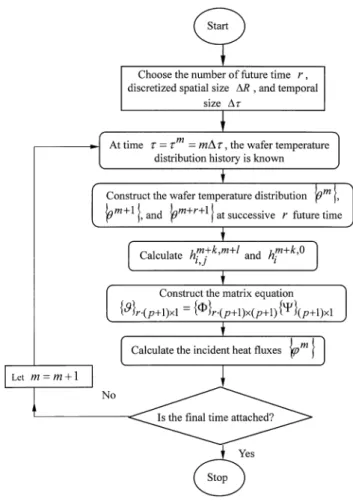
This equation provides a sequential algorithm flow chart as in Fig. 3, which can be used to determine the unknown incident heat fluxes by increasing the value of
m by one for each time step. Thereafter, the incident
heat fluxes can be obtained iteratively along the tem-poral coordinate. Then, the incident heat-flux profiles on the silicon wafer required for tracking uniform temperature trajectories during RTP can be estimated.
4. Results and discussion
To ensure precision and optimal computer use, the
numerical solution techniques with a ps50 equidistant
grid and a time step of Dts0.0001 were used in the present study to compute radial temperature distributions and incident-heat-flux profiles on a typical 300-mm-diameter 0.775-mm-thick silicon wafer. Numerical
sim-ulations linearly ramped from initial uniform
temperature 27 8C(300 K) to a steady state of 1097 8C
Fig. 3. Flow chart to the application of inverse problem algorithm.
Fig. 4. Desired uniform temperature trajectories for 100, 200 and 300 8Cys linear ramp-up rates, and inverse results for random errors of ss0.0, 0.001, and 0.005.
K) were performed to examine the wafer temperature non-uniformity during RTP as a function of the ramp-up rate. Plots of the wafer center temperature for three
linear ramp-up rates, 100, 200 and 300 8Cy s are given
in Fig. 4. While random errors of input data were added to the desired temperature trajectories, as described elsewhere w29x:
n n
Y su qvs,1 1 (27)
where the subscript 1 is the grid number of the
spatial-coordinate at the wafer center, and the superscript n
denotes the grid number of the temporal-coordinate. un
1
is the dimensionless ‘exact’ calculated temperature, Yn
1 is the dimensionless ‘input-measured’ temperature, s is the standard deviation, and v is a random number. The value of v is calculated using the IMSL subroutine DRNNOR and chosen over the range –2.576-v-2.576, which represents the 99% confidence bound for the input temperature. In the present study, the respective
dimensional input temperatures T "0.7728 8C andn
1
T "3.864 8C were simulated for the cases of ss0.001n
1
and 0.005. We set
n n n n n
Y sY s«sY sY2 3 p pq1sY ,1 (29)
as the desired uniform temperature tracking during processing, for the known temperature distribution used in the inverse problem algorithm to evaluate the unknown incident heat-flux profiles over the wafer. After that, the radial temperature distribution across the wafer could be computed. Finally, the wafer temperature non-uniformity both during transient and steady state was investigated.
The inverse wafer-center-temperature trajectory results for three linear ramp-up rates with various random
errors, ss0.0(means ‘exact’), ss0.001 and ss0.005,
are shown in Fig. 4. The transient times from initial
uniform 27 8C (300 K) to reach higher steady state
1097 8C (1370 K) are approximately 10.7, 5.35, and
3.57 s for 100, 200 and 300 8Cy s, respectively. We can
see that the differences between inverse-results and exact-result resulting from the random errors were rea-sonable. The greater the random errors, the less accurate the inverse-results.
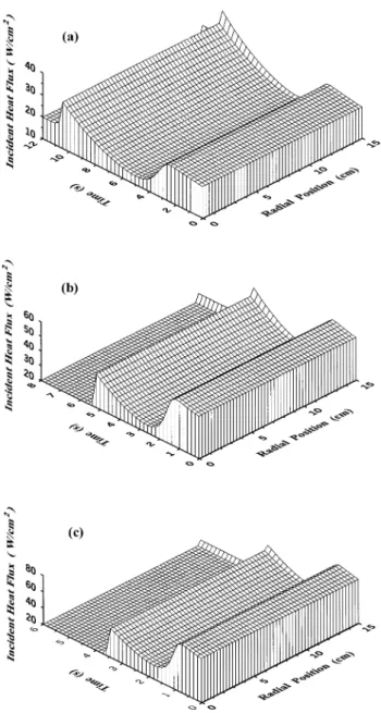
Fig. 5a–c show the three-dimensional graph of the inverse incident-heat-flux profile results with error ss 0.0 for uniform temperature tracking of 100, 200 and
300 8Cy s ramp-up rates, respectively. The axis ‘Radial
Position’ shows the distance from the wafer center in centimeters. The axis ‘Time’ represents the time during this temperature transition. The vertical axis represents the calculated incident-heat-flux profile yielded by the inverse problem algorithm. The incident heat-flux energy is absorbed by top and bottom surfaces of the wafer, and the heat losses also occur at all wafer surfaces. Ramping of wafer temperature takes place when there is an excess of the absorbed energy over the energy of
Fig. 5. Inverse results of incident-heat-flux profiles for a random error of ss0.0 at linear ramp-up rates of(a) 100 (b) 200 and (c) 300 8Cy s.
heat losses. During the initial transient phase, the wafer temperature increases with the increasing absorbed ener-gy, and heat losses also increase with the increasing wafer temperature. The initial absorbed energy, required for wafer uniform-temperature tracking, was larger than that during other periods for this temperature transient. This can be explained by the energy equation for the
silicon wafer wEq. (11)x. On the left-hand side of the
equation, the term ≠uy≠t is constant during processing
because of constant temperature ramp-up rate. Due to uniform temperature tracking, on the right-hand side,
the radial temperature gradient terms, ≠ uy≠R q1yR=2 2
, are approximately zero. The
temperature-Ž
≠uy≠R.
dependent emissivity ´(u) is 0.3 at initial lower
tem-peratures, and 0.68 at higher temperatures from 800 to
1700 K(see Fig. 2). However, the
temperature-depend-ent specific heat capacityC(u) does not vary much with
increasing wafer temperature. Thus the term, ´(u)y
C(u), on the right-hand side of the energy equation at the higher wafer temperature is greater than that at the initial lower wafer temperatures. To balance the energy equation during constant temperature ramp-up process-ing, the net of incident heat flux and heat losses, , is larger in the initial transient phase 4
Ž
.
Ž
.
Q R,t qA 1yu
because of the lower´(u)yC(u). This results in larger
incident heat fluxes being needed in the initial phase. When the wafer temperature reaches approximately 800 K, the necessary incident heat fluxes are reduced due to
the larger´(u)yC(u). While, in the higher temperature
periods, the heat losses occurring at all surfaces become much greater and greater incident heat fluxes are needed to counteract the heat losses. Thus, the necessary inci-dent heat fluxes increase with the increasing wafer temperature until the wafer reaches the higher steady
state (the temperature ramp-up rate becomes zero) and
the necessary incident heat fluxes also become steady because the absorbed energy balances the heat losses. For these cases of three different ramp-up rates, they
are all the same at the value of 20 Wy cm in this2
temperature transient during steady-state processing (after the time of 10.7, 5.35, and 3.57 s for 100, 200
and 300 8Cy s, respectively). Due to the additional heat
losses at the wafer edges, more heat compensation is needed at the wafer perimeters during processing. Since the wafer edge is slightly cooler than the center during the initial transient phase, the edge heating compensation was not significant. As the ramp-up proceeds, the
temperature-dependent thermal conductivity K(u)
decreases with the increasing wafer temperature (see
Fig. 2) and the temperature-dependent emissivity
men-tioned above; the edge heat losses increase with the increasing wafer temperature from the boundary
condi-tion described in Eq.(14). Edge-heating compensations
are increasingly modulated to meet the requirement of uniform temperature tracking. Thus, the additional amounts of energy directed to the edge to offset the edge heat losses are apparent. Finally, as the wafer reaches the steady state, the edge heating compensation approaches the constant heat-flux scaling factor of 1.26 (25.2 Wycm ) for a uniform temperature of 1097 8C2 (1370 K) for these cases of three different linear ramp-up rates. These figures show that the dynamically individual control of incident heat fluxes is needed for tracking the desired uniform-temperature trajectories during RTP. Fig. 6a,b show the inverse incident-heat-flux profiles results from tracking the desired
uniform-temperature trajectory of 200 8Cy s ramp-up rate with
random errors of ss0.001 and ss0.005, respectively. These results are almost the same as those shown in Fig. 5b. However, the incident heat flux profiles have to be dynamically modulated according to the
random-Fig. 6. Inverse results of incident-heat-flux profiles at a linear 200 8Cy s ramp-up rate for random errors of(a) ss0.001 and (b) ss0.005.
Fig. 7. Inverse results of temperature non-uniformity for a random error of ss0.0 at linear ramp-up rates of(a) 100 (b) 200 and (c) 300 8Cys.
error effects to maintain temperature uniformity during both transient and steady state.
Ideally, if it were not for the edge of a wafer, temperature uniformity could be achieved by applying uniform heat-flux profiles of varying strengths on the top and bottom surfaces of a wafer to achieve uniform temperature-trajectory tracking. However, temperature distortions develop near the wafer edges during process-ing. Many rapid thermal processes w20x direct additional amounts of energy toward the edges to counteract these temperature non-uniformities occurring at the wafer edges achieving results similar to our inverse incident-heat-flux results shown in Fig. 5. Inverse dynamic incident-heat-flux profile results on temperature non-uniformity for the three linear ramp-up rates with a random error of ss0.0 are shown in Fig. 7a–c, respec-tively. The vertical axes represent temperature
non-uniformity graphed according to the temperature
differences between points on the wafer and the wafer’s center. These figures show that when incident heat-flux profiles are controlled as our inverse-results, temperature differences develop at the edge. Initially, the temperature difference is not significant, however, as the ramp-up proceeds, the temperature non-uniformity developed at the edge increases with increasing edge-heating compen-sation, as shown in Fig. 5. When temperature-dependent emissivity changes from 0.3 to 0.68, a sudden variation
is seen in the temperature non-uniformity profiles (for
instance, at 4 s in Fig. 7a, in the ramp-up rate of
100 8Cy s). When the wafer reaches the higher steady
state, the incident-heat-flux profile changes from the transient stage to the steady stage, the temperature non-uniformity drops gradually and approaches the
steady-state. Thus, edge-heating compensation has an
overheating effect on temperature uniformity during processing.
Fig. 8. Inverse results of temperature non-uniformity at a linear 200 8Cys ramp-up rate for random errors of(a) ss0.001 and (b) ss0.005.
Fig. 9. Inverse results of maximum temperature difference for random errors of ss0.0, 0.001, 0.003 and 0.005 as a function of the linear ramp-up rate.
Generally, the temperature over the wafer has to be maintained within 2 8C of the wafer center during rapid thermal processing w5x. Fig. 7a–c show that the temper-ature difference from the wafer center is not significant for our present inverse incident-heat-flux profiles. Even though during transient periods, the resulting maximum temperature differences were 0.152, 0.389 and 0.658 8C
for the cases of 100, 200 and 300 8Cy s ramp-up rates,
respectively, it was found that temperature non-unifor-mity occurring during the ramp increased with the ramp-up rate, but within 1 8C during processing. Fig. 8a,b show the respective inverse-results on wafer temperature
non-uniformity for the 200 8Cy s ramp-up rate when the
random errors of ss0.001 and 0.005 were introduced. The temperature non-uniformity increased as the random error was increased, as expected. However, the maxi-mum temperature difference was less than 0.41 8C
although the random error did reach 3.864 8C (in the
case of ss0.005).
Fig. 9 illustrates the resulting maximum temperature
differences ()DT), the absolute value of temperature
difference between the wafer edge and the center) during
transients as a function of the desired linear ramp-up
rates for random errors of ss0.0, 0.001, 0.003 and 0.005, respectively. Our present results show that the maximum temperature differences occurring during the ramp increase with the ramp-up rate. Although a linear
ramp-up rate of 300 8Cy s was used and random errors
did reach 3.864 8C (in the case of ss0.005), the
temperature over the wafer was maintained within 0.665 8C of the wafer center if the incident-heat-flux profiles were dynamically controlled according to the inverse-results. Furthermore, random-error effects on temperature non-uniformity were not apparent when the
desired linear ramp-up rate exceeded 200 8Cy s. When
ramp-up rate was lower than 150 8Cy s, the
random-error effect of ss0.005 on temperature non-uniformity was enlarged due to the dimensional error of 3.864 8C, but remained under 0.35 8C. These temperature non-uniformities could be acceptable in the advanced rapid thermal processing system. The extended model can then be combined with view factor information from more detailed modeling analysis to provide a realistic model for controller design for temperature uniformity problem.
5. Conclusion
This article presents a systematic method to the application of inverse problem algorithms for uniform temperature tracking of several different linear ramp-up rates in rapid thermal processing. Temperature-depend-ent thermal properties of the silicon wafer were consid-ered in this study. Using a one-dimensional thermal model, temperature solutions for the inverse-method matrices can be constructed by applying the
finite-difference scheme to calculate the desired incident-heat-flux profiles required for uniform temperature tracking. In the present study, the wafer was ramped-up from initial uniform 27 8C temperature to a steady state of 1097 8C via simulation at several linear ramp-up rates. The resulting maximum temperature differences as a function of the desired linear ramp-up rates using several random errors were investigated. The maximum temper-ature differences in our present study were only 0.152, 0.388 and 0.658 8C, respectively, for the 100, 200 and
300 8Cy s ramp-up rates when the incident heat fluxes
on the wafer could be dynamically controlled according
to the inverse-results. Temperature non-uniformity
occurring during the ramp increased with the ramp-up rate. Furthermore, random-error effects on temperature non-uniformity were not apparent when the desired
linear ramp-up rate exceeded 200 8Cy s. When ramp-up
rate was lower than 150 8Cy s, the random-error effect
of ss0.005 on temperature non-uniformity was enlarged due to the error of 3.864 8C, but remained
under 0.35 8C. Although a linear 300 8Cy s ramp-up
rate was used and the error did reach 3.864 8C, the resulting maximum temperature differences were not significant and remained under 0.665 8C. These tem-perature non-uniformities could be acceptable in the advanced rapid thermal processing system.
References
w1x V.E. Borisenko, P.J. Hesketh, Rapid Thermal Processing of Semiconductors, Plenum Press, New York, 1997.
w2x K.S. Balakrishnan, T.F. Edgar, Thin Solid Films 365 (2000) 322.
w3x A. Kersch, T. Schafbauer, Thin Solid Films 365(2000) 307. w4x A. Theodoropoulou, E. Zafiriou, R.A. Adomaitis, IEEE Trans.
Semicond. Manuf. 12(1999) 87.
w5x F.Y. Sorrell, M.J. Fordham, M.C. Ozturk, J.J. Wortman, IEEE¨ ¨ Trans. Electron Devices 39(1992) 75.
w6x M. Gluck, W. Lerch, D. Loffelmacher, M. Hauf, U. Kreiser,¨ ¨ Microelectron. Eng. 45(1999) 237.
w7x K.C. Lee, H.Y. Chang, H. Chang, J.G. Hwu, T.S. Wung, IEEE Trans. Semicond. Manuf. 12(1999) 340.
w8x C.H. Huang, C.C. Yu, S.H. Shen, Automatica 36(2000) 705. w9x Y.M. Cho, P. Gyugyi, IEEE Trans. Contr. Sys. Tech. 5 (1997)
644.
w10x A. Theodoropoulou, R.A. Adomaitis, E. Zafiriou, IEEE Trans. Semicond. Manuf. 11(1998) 85.
w11x S. Banerjee, J.V. Cole, K.F. Jensen, IEEE Trans. Semicond. Manuf. 11(1998) 266.
w12x H.A. Lord, IEEE Trans. Semicond. Manuf. 1(1988) 105. w13x C. Hill, S. Jones, D. Boys, Rapid thermal annealing — theory
and practice, in: R.A. Levy(Ed.), Reduced Thermal Processing for ULSI, NATO ASI Series B: Physics, Plenum Press, New York, 1988, pp. 143–180.
w14x R. Kakoschke, E. Bubmann, H. Foll, Appl. Phys. A 50¨ (1990) 141.
w15x R.S. Gyurcsik, T.J. Riley, F.Y. Sorrell, IEEE Trans. Semicond. Manuf. 4(1991) 9.
w16x S.A. Norman, IEEE Trans. Electron Devices 39(1992) 205. w17x J.P. Zollner, K. Ullrich, J. Pezoldt, G. Eichhorn, Appl. Surf. Sci.¨
69(1993) 193.
w18x T.J. Riley, R.S. Gyurcsik, Mater. Res. Soc. Symp. Proc. 303 (1993) 223.
w19x Y.M. Cho, A. Paulraj, T. Kailath, G.A. Xu, IEEE Trans. Semicond. Manuf. 7(1994) 34.
w20x R.H. Perkins, T.J. Riley, R.S. Gyurcsik, IEEE Trans. Semicond. Manuf. 8(1995) 272.
w21x Y.K. Jan, C.A. Lin, IEEE Trans. Semicond. Manuf. 11(1998) 75.
w22x M. Janicki, M. Zubert, A. Napieralski, Microelectron. J. 30 (1999) 1099.
w23x M. Kurz, G. Muller, J. Cryst. Growth 208¨ (2000) 341. w24x J.V. Beck, B. Blackwell, C.R. St.Clair, Inverse Heat Conduction
— Ill-posed Problem, Wiley, New York, 1985.
w25x K. Kurpisz, A.J. Nowak, Inverse Thermal Problems, Computa-tional Mechanics Publications, Boston, 1995.
w26x S. Lin, H.S. Chu, IEEE Trans. Semicond. Manuf. 13 (2000) 448.
w27x S. Lin, H.S. Chu, Microscale Thermophys. Eng. 4(2000) 245. w28x A. Virzi, J. Cryst. Growth 112(1991) 699.