IEEE TRANSACTIONS ON ANTENNAS AND PROPAGATION, VOL. 60, NO. 3, MARCH 2012 1221
Circularly Polarized Crossed Dipole Antenna With
Phase Delay Lines for RFID Handheld Reader
Yi-Fang Lin, Yang-Kai Wang, Hua-Ming Chen, Senior Member, IEEE, and Zhong-Zhe Yang
Abstract—To produce circularly polarized (CP) radiation, a small, double-sided, crossed dipole antenna with two metal strips loaded for phase delay is proposed. The proposed antenna uses two orthogonal, unequal length dipoles, connected in parallel to a coaxial probe feed. It requires no matching network. The required power and phase relationships are obtained by proper choice of dipole lengths and the metal strips attached to them. The antenna also operates at its half wavelength orthogonal modes, for the UHF band. The phase delay metal strip generates the two resonant modes for CP radiation. Simulated and measured results indicate that the crossed dipole structure can produce CP radiation. An impedance bandwidth (VSWR 2) of about 11.8% and a 3-dB axial-ratio (AR) bandwidth of about 3.3% around the center frequency of 925 MHz were measured.
Index Terms—Axial-ratio (AR), circular polarization, crossed dipole antenna, RFID handheld reader.
I. INTRODUCTION
R
ADIO FREQUENCY IDENTIFICATION (RFID) sys-tems in the ultra-high frequency (UHF) band have been generating much interest in several service industries, pur-chasing and distribution logistics applications, manufacturing companies and goods flow systems [1]. An RFID system generally consists of a reader and a tag. In North America and Taiwan, these UHF RFID systems operate between 902–928 MHz, and between 865–867 MHz in Europe. A reader with an antenna sends a radio frequency signal to a tag and receives a backscattered signal from the tag. The reader antenna is an important component in RFID systems and has been de-signed with CP operation in mind, because circularly polarized antennas can increase orientation diversity, although this is achieved at the cost of polarization mismatch losses between the reader and the tag antenna. RFID handheld readers require a light weight CP antenna with a low profile and small size.A typical technique for the generation of CP radiation is to produce two orthogonal, degenerate resonant modes on the ra-diating element, with a 90 phase difference.
Single-feed, circularly polarized, annular-ring, square and circular patch antennas, with symmetrical or asymmetrical
Manuscript received January 17, 2011; revised May 24, 2011; accepted Au-gust 15, 2011. Date of publication December 20, 2011; date of current version March 02, 2012. This work was supported by the National Science Council of Taiwan under Contract NSC 97-2221-E-151-010.
The authors are with the Institute of Photonics and Communications, National Kaohsiung University of Applied Sciences, Kaohsiung 807, Taiwan (e-mail: [email protected]; [email protected]).
Color versions of one or more of the figures in this paper are available online at http://ieeexplore.ieee.org.
Digital Object Identifier 10.1109/TAP.2011.2180319
perturbation elements have all been reported [2]. Using pertur-bation cuts or strips to suitably differentiate the two orthogonal modes at resonant frequency, allows the antenna to easily ra-diate CP waveforms. However, the axial-ratio (AR) bandwidths are usually narrow and cannot meet the bandwidth requirements of modern communication systems. In the design of low profile patch antennas, for RFID reader applications, circular polariza-tion can be generated using slot-coupled radiapolariza-tion elements [3], or by employing a Wilkinson power divider feeding network [4]. These feeding approaches are attractive for broadband CP antenna designs in portable RFID applications, but the antenna size is too large for a handheld device. To improve the oper-ating bandwidth, without increasing the antenna size, a planar crossed-dipole antenna is a good option. In [5], [6], it was shown that single-feed orthogonally crossed dipoles, connected in parallel, could generate CP radiation. If the lengths of the two dipoles are chosen such that the real parts of the input admittances are equal and the angles of the input admittances differ by 90 , the radiated wave generated in the normal di-rection will be circularly polarized. With reference to these conditions, several crossed dipole antennas were developed to improve the bandwidth and AR bandwidth [7], [10]. With reference to size reduction and the required reactance, there are many papers on meander-line antennas, in the RFID context [11], [12]. The meander-line has multiple unequal turns and the adjacent vertical lines of meander-lines allow the storage and loss of electric energy. The overall length of the meander-lines affects the input impedance.
To generate CP radiation, this paper proposes a small, double-sided, crossed-dipole antenna, loaded with two metal strips for phase delay. The proposed antenna uses two unequal length dipoles, connected in parallel to a coaxial probe feed and re-quires no matching network. The antenna operates at its half wavelength orthogonal modes, for the UHF band, and the two resonant modes for CP radiation are generated by the phase delay metal strips. The arms of the dipole antenna use simple meander-lines. This is predominantly for the purpose of size re-duction and not to obtain the required reactance, by optimizing the aspect ratio of the meandering. Details of the antenna de-sign and the experimental results for the antenna performance are presented and discussed.
II. ANTENNADESIGNPROCESS
The configuration of the proposed antenna is shown in Fig. 1. Two meander arms, forming dipole antennas, with phase delay metal strips, are etched on both sides of FR4 substrate (60 60 mm ) with thickness 1.6 mm and relative permittivity of 4.4. The half-wavelength dipole antenna is a linearly polarized
1222 IEEE TRANSACTIONS ON ANTENNAS AND PROPAGATION, VOL. 60, NO. 3, MARCH 2012
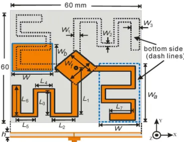
Fig. 1. Geometry of the double-sided circularly polarized crossed dipole antenna.
radiating structure consisting of two quarter-wavelength arms, which shares a commonly fed square metal strips at the center of the substrate. These are fed through a via-hole in the substrate, using a coaxial probe feed. Rhomboid metal strips ( ) are etched at the center of the two sides of the substrate, to en-sure matching of input impedance. Note that each dipole is ar-ranged orthogonally, along the diagonal line of the square strate. One dipole arm is printed on the upper side of the sub-strate while the other arm is on the lower side. Each dipole arm is meandering, to increase the resonant length for a small size antenna. Generation of the circularly polarized waves re-quires a phase difference of 90 , which is satisfied by an an-tenna design consisting of orthogonal dipoles with appropri-ately selected unequal arm lengths. Two rectangular pieces of metal ( and ) are added to the opposite side of the arms of the short dipole for a phase lag. This produces the 90 phase difference. The optimized geometrical parame-ters obtained using Ansoft High Frequency Structure Simula-tion (HFSS) [13], are given in Table I. The proposed antenna was designed to operate at 925 MHz (UHF band), to produce the CP radiation. The resonant length of the long dipole is 208
mm ( ), corresponding
to about 0.63 of 908 MHz. Using the reflection formula , as follows, a simulated input impedance and resultant phase can be determined:
The phase angle of , for the long dipole, is about . Similarly, the resonant length of the short dipole is 196 mm
( ), corresponding to about
0.62 at 946 MHz. The input impedance and phase angle as are
Fig. 2. Simulated phase diagram versus frequency for the proposed antenna.
Fig. 3. Simulated current distributions on the proposed LHCP antenna at 925 MHz. At four phase angles: (a) 0 , (b) 90 , (c) 180 , (d) 270 .
Clearly, the relative phase difference between the two dipoles is about 88 ; so this design satisfies the phase requirement for the generation of CP radiation. Fig. 2 shows the simulated phase diagram for the proposed antenna. It can also be seen that the two orthogonal modes ( 908 MHz and 946 MHz) are excited, in 90 phase difference, resulting in good CP ra-diation. The simulated current distributions for the proposed antenna, shown in Fig. 3, can be employed to explain the CP radiation. It can be observed that the current distributions are located in each dipole for four phase angles of 0 , 90 , 180 , and 270 , respectively. An instantaneous current phase in the center of the proposed antenna, at 90 intervals, demonstrates a very strong left-handed circularly polarized (LHCP) wave; that is, the current flows turn the -axis into the -axis, like a left-handed circular polarization. Note that the right-handed cir-cularly polarized (RHCP) radiation can be obtained by changing the arms of the crossed dipoles. The two individual half-wave-length dipole antennas also have typically larger relative current near the middle and zero current at the ends of the dipole arms.
LIN et al.: CIRCULARLY POLARIZED CROSSED DIPOLE ANTENNA WITH PHASE DELAY LINES FOR RFID HANDHELD READER 1227
Yang-Kai Wang was born in Kaohsiung, Taiwan,
in 1976. He received the M.S. degree from the Department of Physics, Tamkang University, Taipei, Taiwan, in 2004. He is currently pursuing the Ph.D. degree from the Department of Electrical Engi-neering, National Kaohsiung University of Applied Sciences, Kaohsiung, Taiwan.
He is currently working on design of circularly polarized antenna at school. His main research interests include circularly polarized operation and ceramic material of antenna, especially using the slot antenna for RFID and GPS applications.
Hua-Ming Chen (M’98–SM’06) received the B.S.
degree in physics from National Tsing Hua Univer-sity, Hsinchu, Taiwan, the M.S. degree from the Insti-tute of Electro-Optics, National Chiao Tung Univer-sity, Hsinchu, Taiwan, and the Ph.D. degree in elec-trical engineering from National Sun Yat-Sen Uni-versity, Kaohsiung, Taiwan, in 1983, 1987, and 1996, respectively.
Since 1988, he has been with the Institute of Photonics and Communications, National Kaoh-siung University of Applied Sciences, KaohKaoh-siung, Taiwan, where he became a Professor in 2001, where he also served as Director of Institute of Photonics and Communications from 2005 to 2008. He has published more than 110 journal and conference papers and holds 18 patents on antenna design. Several of his antenna designs have been licensed to industry for production. His current research interests include microstrip antennas, dielectric resonator antennas, RFID antennas, and microwave circuit design.
Dr. Chen has been serving as the Chair of IEEE AP-S Tainan Chapter, Trustee of IEEE Tainan Section, Trustee of Chinese Microwave Association and Trustee of the Institute of Antennas Engineers of Taiwan (IAET) since 2009. He also served as a Technical Program Committee member of IEEE TENCON 2007, International Technical Program Committee member of IEEE AEM2C 2010 and IEEE iWEM 2011 in Taiwan. He was also listed in Who’s Who in Science and Engineering and Who’s Who in Asia.
Zhong-Zhe Yang was born in Taichung, Taiwan,
in 1985. He received the M.S. degrees from the Institute of Photonics and Communications, Na-tional Kaohsiung University of Applied Sciences, Kaohsiung, Taiwan, in 2010.
His main research interests include planar circu-larly polarized antennas for communication applica-tions, especially applying for the handheld devices.