880 IEEE TRANSACTIONS ON MICROWAVE THEORY AND TECHNIQUES, VOL. 44, NO. 6, JUNE 1996
Riccati Matrix Differential
E
Formulation for the Analysis of Nonuniform
ultiple Coupled Microstrip Lines
Jen-Tsai
Kuo,
Member, IEEEAbstruct- A Riccati matrix differential equation (RMDE) is formulated for analyzing nonuniform coupled microstrip lines (NCML’s) in the frequency domain. The formulation is based on a reciprocity-related definition in the theory of multiconductor transmission lines under quasi-TEM assumption. The hybrid- mode nature of modal phase velocities and strip characteristic impedances for multiconductor microstrip structure is included. The nonlinear RMDE is first transformed into a first-order linear differential matrix equation which can be efficiently solved using method of moments. A convergence study is performed to investi- gate the sufficient number of basis functions used in the method. The voltage-scattering parameters of a tapered microstrip and two three-line structures are presented. The frequency responses of a pair of nonuniform coupled lines are measured and compared with calculated results.
I. INTRODUCTION
ONUNIFORM coupled microstrip lines (NCML’s) play an important role in both analog and digital microwave integrated circuits. Using NCML’s, for example, a folded all- pass two-port network [ l ] and a directional coupler [l], [2]
can be realized with high coupling values operating over an ultra-wide frequency band. To date, NCML’s serve as the interconnections in most chip packages for digital inte- grated circuits of switching speed covering the microwave or millimeter-wave regime [3]-[9]. With the advances of today’s semiconductor fabrication technology, the major portion of delay time in a microwave integrated circuit (MIC) can be due to these interconnection lines [3]. One possible way for reducing the delay time is to increase the density of the interconnecting NCML’s. As the NCML’s become shorter
or are placed closer, the nonuniformity of the lines must be properly designed in order to obtain transmitted signals with sufficiently high quality.
When high-speed signal travels along NCML’s, the received signal at the load end can be degraded due to 1) dispersion, 2)
cross talk, 3) losses, and 4) reflections. The cross talk and dis- persion are due to the differences of relative effective dielectric constants for different modes and at different frequencies, respectively. The losses which include conductor, dielectric, and radiation attenuation factors will lower the power level of Manuscript received August 22, 1995; revised February 15, 1996. This work was supported in part by the National Science Council, Taiwan, Grant NSC 85-221 3-E-009-002.
The author is with the Department of Communication Engineering, National Chiao Tung University, 1001 Ta-Hsueh Road, Hsinchu, Taiwan, R.O.C.
Publisher Item Identifier S 001 8-9480(96)03783-0.
the received signal. If the lines are electrically short and made on a low-loss substrate, the radiation can dominate the loss mechanism. Reflections are caused by the position-dependent impedance values along the lines. Note that all the aforesaid factors depend on the nonuniformity of the lines and on the operation frequency which make the characterization of the NCML’s network become a complicated task.
Several methods have been developed to analyze multiple NCML’s. Mehalic and Mittra [4] investigated the tapered multiple microstrip lines using a spatial iteration-perturbation approach technique. Oh and Schutt-Aine [5] analyzed the nonuniform lines based on a time-domain scattering parameter formulation incorporated with the closed-form expressions of voltage variables for divided short uniform lossless lines. Mao and Li proposed a method of convolution-characteristic [6] and a method of equivalent cascaded network chain [7] to handle the transient response of NCML’s. Palusinski and Lee [3] used Chebyshev polynomials to expand the current and voltage along the nonuniform lines in the time-domain to predict the reflections and cross talk of general multiple coupled line systems.
In frequency domain, Arabi et al. [8] presented an electri- cal field integral equation formulation based on a combined approach of using closed-form near and far field approxima- tions for the Sommerfeld microstrip Green’s functions. The accuracy of this technique can be set to any desired value. In
[9],
Pan and his colleagues extended the method in [3] to the frequency domain. The advantages of analyzing NCML’s in the frequency domain over the time domain were also discussed.To calculate the input reflection coefficient matrix of ter- minated NCML’s, we derive a differential matrix equation, which is known as the Riccati matrix differential equation (RMDE), based on a reciprocity-related definition of the line voltages and currents for hybrid-mode multiple coupled mi- crostrips. The RMDE is expressed in terms of the normal mode parameters of coupled microstrips and solved by method of moments. The method of solution is also extended to calculate the scattering parameters of 2N-port NCML’s networks.
The presentation is organized as follows. Section I1 de- scribes the background of the mathematical modeling of NCML’ s and lists the mathematical formulas to describe the reflection along the lines. Section I11 presents the method of solution to the nonlinear RMDE. In Section IV, the conver- gence behavior of the analysis method is investigated and 0018-9480/96$05.00 0 1996 IEEE
KUO: RICCATI MATRIX DIFFERENTIAL EQUATION FORMULATION
~
88 1
Fig. 1. A system of N-conductor nonuniform coupled microstrip lines.
several numerical aspects are discussed. Numerical results for certain nonuniform single microstrip and. three-line structures are presented and discussed. Section V compares the mea- sured frequency responses of a nonuniform two-line structure with the calculated results. Finally, Section VI draws the conclusion.
11. THE RICCATI MATRIX DIFFERENTIAL EQUATION (RMDE) It is known that a system of uniform N-conductor coupled microstrip lines and a ground line support N dominant or quasi-TEM modes. For the NCML’s in Fig. I , we neglect the fringing fields, which produces radiation loss, caused by the gradual change of waveguide cross section. For lines with abrupt discontinuities, field-theoretical oriented formulations, such as that in [SI, can be referred to enhance accuracy of results. At any z along the NCML’s, through the full-wave solution, an N x N matrix [MI], called the eigencurrent matrix, can be obtained [lo]. Of [MI] each column vector consists of total currents on the lines for a given mode. Based on the orthogonality of modal voltage and current vectors, an eigenvoltage matrix [Mv] iis uniquely defined [ I l l . For each mode, inner product of the eigenvoltage and eigencun-ent vectors is set to be the total electromagnetic power transfer. This is an important fact that lleads our field problem to be able to be formulated by circuit quantities.
The characteristic admittance matrix along the lines is given by [111
It can be shown that [Yc] is symmetric and the important aspect of reciprocity is guaranteed. If the load network has an admittance matrix identical to the [Yc] of the NCML’s at the load end, then there is no reflection.
The equivalent distributed capacitance matrix [C] and in- ductance matrix
[L]
along the lines can be derived [lo][CI
= [MI] diag ( P k I W ) [Mv] [LI = [Mvl diag ( P k I W ) [&‘I] -l(2) (3)
where w is the angular frequency and p k iis the phase constant
of the kth mode. Note that all the entries in [MI], [Mv], [Yc], [L], and [C] are dispersive and position-varying along the NCML’s. Let [I] and [VI be the line current and line voltage column vectors of which the kth entries are the total current and voltage on the kth line, respectively. Then, from the multiconductor transmission-line theory [3]
[I]
= [Y,nI[Vl (4)[VI’ =
-PI
[I1
( 5 )
[I]’ = -[YI[VI (6)
where
[Kn]
is the input admittance matrix :seen at z toward the load, [Z] and [Y] are, respectively, the series impedance and shunt admittance matrices per unit length of the NCML’s, and the prime (’) represents the derivative with respect to z . If the tapered lines are lossless,[Z] =
j w [ L ]
and [Y] = jw[C]. Let the reflection coefficient matrix along the longitudinal direction be [ p v ] , then [Y,,] and [pv] are related by [lo][Knl
= [YCl([Ul - [Pvl)([Ul+
[pvl)r1 (7) where [U] is the identity matrix of size N x N . Substitution of (4) and (5) into (6) leads to[
L
I
-’
[Knl[~l[Y,,l
+
[ Y ] = 0.[PVI’ = j([YI[Pvl
+
[PVI[‘Yl)(8)
Inserting (7) into (S), one obtains
882 IEEE TRANSACTIONS ON MICROWAVE THEORY AND TECHNIQUES, VOL. 44, NO. 6, JUNE 1996
where
[r]
= [Yc]-'[Y] = [Z][Yc] = [ M ~ ] d i a g ( , & ) [ - M \ - ] - ~ and [GI = [ Y ~ ] - ~ [ Y c l ' / 2 . Note that (8) and (9) are known as the RMDE [12] which is nonlinear. It is believed that [13] is the first literature that formulated the RMDE (8) for studying general nonuniform transmission lines.In the case of single nonuniform line, (9) becomes the Riccati scalar differential equation (RSDE) [ 121. To simplify this nonlinear differential equation, many authors [ 14-16] neglected the p i term. The solution of pv at z = 0 can then be obtained through a simple Fourier transform of a function of the line characteristic impedance. Based on the transform, synthesis of matching transformers and couplers using nonuniform transmission lines have been developed [ 151,
[16]. Note that the legitimacy of the negligence is relied on the fact that p:
<<
1 along the line. Thus, an error in pvwill be generated at low frequencies for lines used to match impedances with large ratio. The following section formulates the method of solution to (9) in which no such error will occur.
111. METHOD OF SOLUTION
It is found that the RMDE can always be transformed into a linear equation [12]. This can be done by defining
where [A121 = [A211 = [GI and [A221 = [All]* =
j[r]
-[G] for lossless NCML's. The asterisk denotes the complex conjugate operation. It has been shown in [12] that if
[ D ]
and[R]
satisfy (10) then[PVI = [Rl[Dl-l (11)
is the solution to (9) provided that [ D ] is nonsingular for all
z . The matrix equation (10) can be rewritten as
[XI! = [AI[Xl (12) where [XI = [DTRTIT and the superscript T stands for the transpose operation. It is interesting to note that if [VI and [I]
in (4) through (6) are replaced by
Ma
1x1
= C[XmIc,,,(z) (16)m = O
where C, (2) is the shifted Chebyshev polynomial of order m
of the first kind defined over 0
5
z5
L, L being the length of the NCML's, and [X,] and [A,] are constant matrices. The matrix [A] is first expanded into a linear combination of C m ( z ) of which each coefficient matrix can be obtained by Gaussian Chebyshev quadratures [19]. Then [Am]s can be obtained since each C m ( z ) is known as a polynomial of z of degree m. Following the method in [20], more precisely the Galerkin procedure in method of moments, one can obtain[XI
=
[Ql[W)I
(17)and
Mi
[&I-'
= [UI+
[Am] 8 ([pI[Hl") (18) where[U]
is the identity matrix of size 2N(M2+1) x 2 N ( M 2 +1).
[PI and
[HI
are the operation matrices of integration and of z-multiplication, respectively, of the shifted Chebyshev polynomials. They are given byA0 A 1 A 2 A3 -a0 0 - 7 2 0 0 -a1 0 - q 3
. . .
m=O 0 0 [PI =I
0 0 -a2 0 and [HI = (L/2)[HOI (20)where a , = L/2, CYk = L/4(k
+
1) for IC2
1, qO = q1 = 0,q k = L/4(1- I C ) for k
2
2, and Ak = a k + q k for k2
0. [H,]is a tridiagonal matrix with all diagonal entries and the (2, 1)th one being 1 and all the other nonzero entries being 0.5.
In (18), 8 denotes the Kronecker product, defined as
where
[V+]
and [V-] are the forward and backward traveling voltage wave vectors along the NCML's, then one can find that [V*] = [V+TV-T]T also satisfies (12). In other words, the nonsingular matrix [D] consists of N linearly indepen- dent [V+]s as its column vectors and [R] consists of the corresponding N [ V - ] vectors.Analytical solution to (12) is difficult or impossible to obtain since the eigenvalues and eigenvectors of the complex matrix function [A] are position-dependent [ 171. To solve (12), we use the method of moments which is closely related to the case of a single nonuniform line in [18]. [A] and [XI are expanded as
Note that only the entries in the first 2N columns in [Q] are useful in calculating the network parameters since [ X ( L ) ] = [D(L)TR(L)TO 0 .
. .
0IT. If [Q] is partitioned into 2(M2+
1) x 2(M2+
1) submatrices [4Iz3, of each the size isN x
N ,
then it can be readily shown that(22)
(23)
[V+(O)] = [A,,][V+(L)]
+
[Al2][V-(L)][v-
(0)l = [a,I][V+(L)l+
[a,,][V-(L)l withKUO: RICCATI MATRIX DIFFERENTIAL EQUATION FORMULATION 883 4 6 8 10 12 z = o z=L
Fig. 2. Planar view of the nonuniform coupled microstrips for investigating convergence behavior of the method. The load is assumed perfectly matched.
W ( z ) = 0.36
+
0.84(z/L) mm, S ( z ) = 1.8 - W ( z ) mm, L = 10 mm. The dielectric substrate has eT = 12.9 and height h = 1 mm.4 5 6 7 8 9 10 2.0353 2.0353 2.0379 2.0385 2.0385 2.0386 2.0387 1.9514 1.9318 1.9325 1.9325 1.9325 1.9322 1.9320 1.9569 1.9364 1.9370 1.9379 1.9379 1.9379 1.9379 1.9569 1.9359 1.9365 1.9375 1.9375 1.9376 1.9376 1.9569 1.9360 1.9365 1.9375 1.9375 1.9376 1.9376 P. m I 0.2 - v c C 0 E a 0 c 0 0 .- .,.
.-
t 0.1 - m - .,. E\
\
I
ZL,
' 0 . '\ n
0.0 L 0.02 0.05 0.1 0.2 0.5 1 2 5 10 20 Frequency (GHz)Fig. 3. Comparison of the input reflection coefficients of an exponential microstrip taper on a substrate with eT = 8 designed for transforming
2s = 63.58 R to ZL = 117.99 R, L = 9 h = 9 mm. Response (a) is the complete solution to the RSDE and (b) is that to the RSDE with the p:
term being omitted. The width profile of the tapered microstrip see [16, Fig. 71. The line characteristic impedances use dc values.
TABLE I
CONVERGENCE ANALYSIS OF THE PROPOSED METHOD
M I 4 5 6 7 8 9 1 0 1
1.0058 1.0058 1.0076 1.0074 1.0074 1.0074 1.0075 1.0936 1.1008 1.1004 1.1004 1.10105 1.1006 1.1003 1.0890 1.0968 1.0969 1.0965 1.0966 1.0966 1.0966
matrix can be found as
IV. RESULTS
A, The Database of NCML's Normal Moore Parameters To calculate the 2N-port parameters of NCML's, we use spectral domain approach (SDA) [lo] to evaluate the normal mode parameters. For all NCML's addressed in this paper, the evaluations are sampled at z , = m.L/20, m = 0(1)20, with L being the length of lines, for frequencies at 0.5n GHz,
n
= integer. At each frequency point, each entry of[r]
and [GI in (9) is approximated by a cubic spline interpolation for use in the numerical quadrature for finding [A,]s in (15).Following the voltage scattering parameter matrices used in B. Convergence Study and Some Numerical Aspects
Table I shows convergence behavior of' the input reflection coefficients [ p v ( 0 ) ] for a tapered two-line structure of which the planar geometry is drawn in Fig. 2. 'The even- and odd- modes are found to have relative effective: dielectric constants close to 9, thus the length of lines is about one guided [21] and defining
(25) one can obtain
wavelength for both modes at 10
GHz. Note that, due to
the structural symmetry, I[pv(0)](2, 2)1 = I[pv(O)](l, 1)1 and In Table I, the listed results are accordiing to values of MI [Sll] = [&l][&l]-'[SlZI = [A221 - [ ~ 2 , 1 [ A l l l - 1 [ ~ 1 2 1 (26b)
I[PV(0)1(2> 111 = I[Pv(O)l(l, 2)l.
[ S Z l ] = (26C)
[ S Z Z I = - [ ~ l l l - ' [ ~ l ~ l . (26d) (See (15)) and M2 (See (16)) ranging from 4 to 10 and from 4 to 12, respectively. The execution CPU time is dominated by M2 for setting up the matrix [Q] in (18). For both the (1, 1)th and (1, 2)th values, it shows that using 111, = 4 produces results with errors with several percents. For M Z
2
8, whenMI
is increased from 6 to 10, both sets of the reflection values converge to at least four significant digits. According to our experience, to have the same converged results at 20 GHz, it requires MI = Mz = 12.The voltage scattering pararneter matrices can be used to characterize the 2N-port NCML's network for any linear time-invariant termination conditions at both the source and the load ends. However, (22) and (23) are still useful in calculating some important network parameters. For example, when [pv(L)] exists at the load end, then the input reflection
884 IEEE TRANSACTIONS ON MICROWAVE THEORY AND TECHNIQUES, VOL. 44, NO. 6, JUNE 1996 0.0 0.25 ~ Structure A I I I I I I I I I Structure B Line 1 Line 2 Line 3 Z=O Z=L 0.10 A:(l,3); B:(1,2) and (2,3) 0.05 0.00 0 1 2 3 4 5 6 7 8 9 10 F r e q u e n c y ( G H z ) (a) 1.3 I I 1.2 1.1 0.85 I I 0.80 0 75 ~ 0.25 0.20 0.15 0.10 0.05 0.00 ro" -
4
I 0 1 2 3 4 5 6 7 8 9 10 Frequency (GHz) 0.25 I ~ Structure A Structure B 0 10-
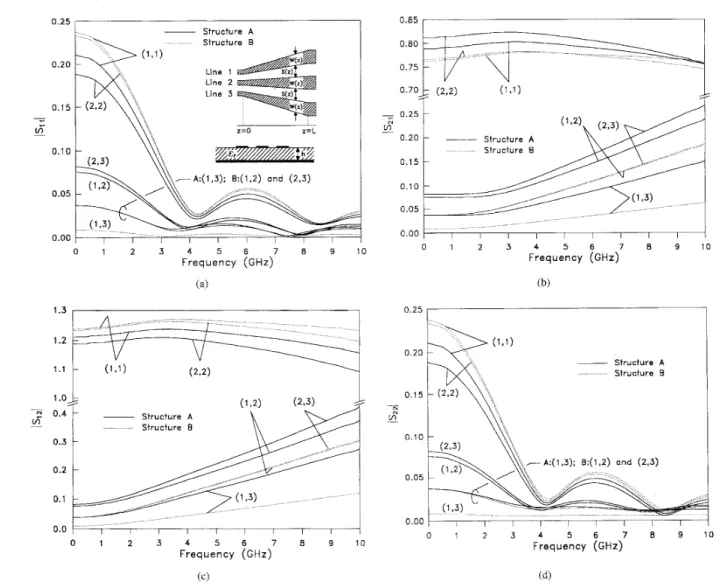
A:(l,3); B.(1,2) and (2,3) 0 05 0 00 0 1 2 3 4 5 6 7 8 9 10 Frequency (GHz) Fig. 4.L = 20 mm. S ( Z ) = 0.5W0(l
+
z / L ) for structure A and S ( z ) = 2 . 5 W 0 ( 1+
z / L ) for structure B. (a) ISii1. (b) /szil. ( c ) (siz1. (d) Iszzl. The voltage-scattering parameters for two tapered three-line microstrips. h = 0.508 mm, t r = 4.2, W ( z ) = Wo(l+
2 z / L ) , W , = 0.24 mm, andC. The Input ReJection Coeficient f o r a Tapered Microstrip
To calculate the reflection coefficient of a nonuniform microstrip, the Riccati scalar differential equation (RSDE)
reduced from (9) can be invoked. When the p$ term is omitted in the equation, it is equivalent in our method of solution to enforce that [A121 = 0 and [A221 = [ A l l ] * = j [ 7 ] (See (10)). Therefore it is easy to investigate the effectiveness of the negligence of the p t term on the results using our readily developed program. We use an exponential microstrip taper, of which the x-dependent width profile is in [16, Fig. 71, as the test structure. The line characteristic impedances use the dc values. The length of the line is 9 mm which corresponds to L/X, = 0.6 at 20 GHz.
The taper is designed for transforming
ZL
= 117.99R
to ZS = 63.58 CL. So the reflection coefficient at dc is(ZL
-Zs)/(Z,
+
2s)
E 0.3. In Fig. 3, the solid and dotted responses compare the solutions to the RSDE with and without the p t term. Both curves agree very well for frequencies higher than 3 GHz, at which the line is about one fifth of guided wavelength. The values of lp,(O)I for both cases havea deviation of 3% for frequencies less than 1 GHz where the value of p v ( z ) remains nearly constant (0.3) all over the line. It is believed that the influence of neglecting the p: term on the solution to the RSDE for analyzing tapered microstrip is reported for the first time.
D. The 2N-Port Network Parameters for Tapered Three-Line Structures
Fig. 4 compares responses for two tapered three-line struc- tures with the same line width geometry but different line spacing. The solid lines represent the parameters for structure A which has smaller line spacing. More interline coupling or cross talk voltage level is expected for structure A than B.
Again, due to the structural symmetry, only five entries of each S-parameter matrix need specifying.
Before we look into details on the 2N-port parameters of the NCML's, let us review certain important formulas that can help understanding of the results. The S-parameters we use here are based on the voltage wave instead of power wave definition. Thus, at zero frequency, the [Sll] and [Szl]
KUO: RICCATI MATRIX DIFFERENTIAL EQUATION FORMULATION 885
are, respectively, the reflection ([pv]) and transmission
(
[Tv])coefficient matrices of a step impedance junction with source admittance matrix [Yc(O)] and load [Yc(L)], i.e., [lo]
(27) [PVI = ([Yc(O)l+ [Yc(L)l)-l([Yc(o)l - [Yc(L)I) and
[Tv] = 2([Yc(O)]
+
[ Y ~ ( L ) ] ) - ~ [ y c ( o ) ] . (28) The results of [ S ~ P ] and[S~Z]
matrices at dc can be known in a similar fashion. For closely packed symmetrical three-line microstrip [lo], [Yc](2, 2)<
[Yc](l, 1) = [Yc](3, 3) and the diagonal elements of [Ye] decrease as the line spacing is decreased. Thus, the [Yc](k,IC),
IC = 1, 2, and 3, for structure A are smaller than those forW.
Fig. 4(a) compares the lSlllresponses. For each structure, entry (1, 1) is larger than entry (2, 2). It means that, when the lines are perfectly terminated at the load end, the relative reflection at line 1 due to an excitation at line 1 is larger than that at line 2 due to an excitation at line 2. Entries (1, 1) and (2, 2) for structure
B,
which has smaller interline coupling, have closer and larger values than those for structure A. However, entries (1, 2), (2, 3), and (1, 3) forB
are smaller than those for A.The forward transmission coefficient or IS21
I
responses are plotted in Fig. 4(b). Structure A has larger entry values thanB. The (1, 1) and (2, 2) values are firstly increased at lower frequencies and reach their maxima at about 4 GHz, where the ISlll entries have their minima, then decrease as frequency is further increased due to the increase of magnitudes of entries (1, a), (2, 3), and (1, 3). These three entries can be interpreted as the “cross talk” for this NCML’s structure.
The IS121 responses are shown in Fig. 4(c). The relative cross talk voltage levels are larger than those for 15’21
I
entries. Note that these cross talk voltage levels are not zero at dc. This can be explained from (28). Entries (1, 1) and(2,
2) for structure B are larger than those for structure A.The
I
S22I
responses are plotted in Fig. 4(d). According to (27), the 15’22I
entries should have nearly the same magnitudes as the corresponding ones of15711
I
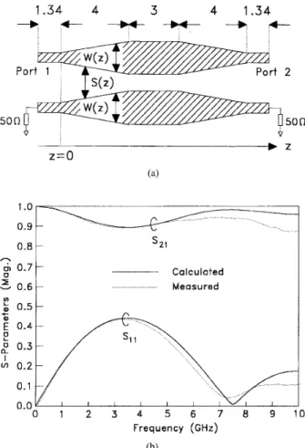
at lower frequencies. D. Experimental MeasurementsWe measure the responses of a pair of symmetrical nonuni- form coupled microstrips of which the planar view is shown in Fig. 5(a). At both ends of the circuit, the line width is chosen to have 50
R characteristic impedance and the spacing
is 3.5 times the width so that the interline coupling can be neglected [IO]. The test circuit is fabricated on a low-loss alumina substrate (er = 9.9, loss tangent tan6
5
0.001). A TaN (Tantalum Nitride) thin film resistive layer, sandwiched between the substrate and metal, can be used for termination design. The termination resistance value should be carefully trimmed during the fabrication process since improper termi- nation condition will cause unwanted reflections.The measurement is performed using the HP85 1 OB network analyzer and the results are shown in Fig. 5(b). The agreement between the calculated and measured
I
responses is fairly good. The predicted IS21I
response, however, begins to deviate1.34
4
34
1.34 + + 4 & + 4 - - -50n
50n
h d, 0.7 Calculaited Measured D Frequency (GHi!) (b)Fig. 5. The results for the experimental nonuniform coupled microstrips.
F, = 9.9, h = 0.254 mm, W1 = 0.254 mm, WZ = 0.635 mm, SI = 0.889 mm, 5’2 = 0.508 mm, W ( z ) =
+
( W Z - W1)%/4, and S ( z ) = SI+
(SZ - s 1 ) Z / 4 . The structure is symmetric about z = 5.5 mm. (a) Circuit geometry. (b) Measured and calculated responses.from the experimental results at 5 GHz where the length of line is about one half guided wavelength. The deviation could be caused by dielectric ( a d ) , conductor ( a c ) , ;and radiation losses.
Similar deviation is also reported for a tapered three-line structure [4], where the fitness of prediction and measurement can be made up at lower frequencies by including the a d
and a , factors, but the radiation loss is still significant at the higher frequency end. Note that the electrical length of the test circuit in Fig. 5 is only about one sixteenth of that used in [4]. According to our experience of designing multiple coupled microstrip lines on alumina substrate [lo], the attenuation factor including a d and a , is approximately 0.01 dB/mm. Thus a d and a , could have only limited contribution to the deviation
in our experiment and the deviation should be mainly due to the radiation caused by the line width nonuniformity.
V. CONCLUSION
A RMDE has been formulated for calculating the 2N-
port network parameters of nonuniform multiple coupled mi- crostrips. The influence of neglecting
$,
term in the Riccati scalar differential equation on the input reflection coefficient response of a microstrip taper is investigated. From the in-886 IEEE TRANSACTIONS ON MICROWAVE THEORY AND TECHNIQUES, VOL. 44, NO. 6, JUNE 1996
vestigation of two tanered three-line microstrios. the smaller ” 1101 J.-T. Kuo and C.-K. C. Tzuann. “A termination scheme for high-meed . - ” - I
is the line spacing or the higher is the operation frequency, the higher is the crosstalk level. From the experimental two-
pulse propagation on a system of tightly coupled coplanar strips,’’ IEEE Trans. Microwave Theory Tech., vol. 42, pp. 1008-1015, June 1994. [ I l l L. Wiemer and R. H. Jansen, “Reciprocity related definition of strip . . line structure, the calculated and measured results agree well - characteristic impedance for multiconductor hybrid-mode transmission
lines,” Microwave Opt. Tech. Lett., vol. 1, pp. 22-25, Mar. 1988. 1972.
at lower frequencies and Start to deviate at the frequency at [I21 W, T, Reid, Riccati Differential Equations, New Yo&: Academic, which the radiation loss, due to the line width nonuniformity,
becomes important. [I31 R. L. Stemberg and H. Kaufman, “Applications of the theory of systems
of differential equations to multiple nonuniform transmission lines,’’ J.
Math. and Phys. vol. 31, pp. 244-252, 1952.
[14] R. W. Klopfenstein, “A transmission line taper of improved design,” Proc. IRE, vol. 44, pp. 31-35, Jan. 1956.
r151 D. Pramanick and P. Bhartia, “A generalized theory of tauered trans-
ACKNOWLEDGMENT
The author would like to thank the Microelectronic Tech- . .
-
nology Inc., Hsinchu, Taiwan, for their support in fabricating the measured circuits and to T.-Y. Wu in ERSO, Hsinchu, Taiwan, for his help in the measurement works.
mission line matching transformers and asymmetric couplers supporting non-TEM modes,” IEEE Trans. Microwave Theory Tech., vol. 37, pp. 118&1191, Aug. 1989.
[16] M. Kobayashi and N. Sawada, “Analysis and synthesis of tapered microstrip transmission lines,” IEEE Trans. Microwave Theory Tech., vol. 40, pp. 1642-1646, Aug. 1992.
1171 S. Amari, “Comments on ‘An exact solution for the nonuniform trans- REFERENCES
[ I ] S. Yamamoto, T. Azakami, and K. Itakura, “Coupled nonuniform transmission line and its applications,” IEEE Trans. Microwave Theory Tech., vol. M’M-15, pp. 220-231, Apr. 1967.
[2] S. Uysal and H. Aghvami, “Synthesis, design, and construction of ultra-wide-band nonuniform quadrature directional couplers in inhomo- geneous media,” IEEE Trans. Microwave Theory Tech., vol. 37, pp. 969-976, June 1989.
[3] 0. A. Palusinski and A. Lee, “Analysis of transients in nonuniform and uniform multiconductor transmission lines,” IEEE Trans. Microwave Theory Tech., vol. 37, pp. 127-138, Jan. 1989.
[4] M. A. Mehalic and R. Mittra, “Investigation of tapered multiple mi- crostrip lines for VLSI circuits,” IEEE Trans. Microwave Theory Tech., vol. 38, pp. 1559-1567, Nov. 1990.
[ 5 ] K. S . Oh and J. E. Schutt-Aine, “Transient analysis of coupled, tapered transmission lines with arbitrary nonlinear terminations,” ZEEE Trans. Microwave Theory Tech., vol. 41, pp. 268-273, Feb. 1993.
[6] J. Mao and Z. Li, “Analysis of the time response of multiconductor transmission lines with frequency-dependent losses by the method of convolution-characteristics,” IEEE Trans. Microwave Theory Tech., vol. 40, pp. 637-644, Apr. 1992.
[7] -, “Analysis of the time response of nonuniform multiconductor transmission lines with a method of equivalent cascaded network chain,” IEEE Trans. Microwave Theory Tech., vol. 40, pp. 948-954, May 1992. [8] T. R. Arabi, A. T. Murphy, and T. K. Sarkar, “Electrical field integral equation formulation for a dynamic analysis of nonuniform microstrip multi-conductor transmission lines,” IEEE Trans. Microwave The001 Tech., vol. 40, pp. 1857-1869, 1992.
[9] G. Pan, G. J. Wunsch, and B. K. Gilbert, “Frequency-domain analysis of coupled nonuniform transmission lines using Chebyshev Pseudo- spatial technique,” IEEE Trans. Microwave Theory Tech., vol. 40, pp. 2025-2033, Nov. 1992.
. .
mission line problem,” IEEE Trans. Microwave Theory Tech., vol. 39, pp. 6 1 1 4 1 2 , Mar. 1991.
[ 181 R. F. Hanington, Field Computation by Moment Methods. New York: Macmillan, 1968.
1191 H. Engels, Numerical Quadraiure and Cubature. London: Academic, 1980.
[20] T. Lee and S. Tsay, “Analysis, parameter identification and optimal control of time-varying system via general orthogonal polynomials,” Int. J. System Sci., vol. 20, pp. 1451-1465, 1989.
[21] C. R. Paul, Analysis of Multiconductor Transmission Lines. New York: Wiley, 1994, ch. 8.
Jen-Tsai Kuo (S’89-M’93) received the B.S. de- gree in communication engineering from the Na- tional Chiao Tung University (NCTU) in 1981, the M.S. degree in electrical engineering from the National Taiwan University in 1984, and the Ph.D. degree from the Institute of Electronics, NCTU in 1992, all in Taiwan.
Since 1984, he has been with the Department of Communication Engineering at the NCTU as a Lecturer at both the Microwave and Communication Electronics Laboratories. Since 1995. he has been a Visiting Scholar at the University of Califomia at Los Angeles. His research interests include the analysis and design of high-frequency electronic and microwave circuits, high-speed interconnects and packages, field-theoretical studies of guided waves, and numerical techniques in electromagnetics.