Abstract
Wireless local loop (WLL) provides two-way calling services to the stationary or “fixed” users, which is intended to replace its wireline counterpart. Today, there are almost 100 WLL systems (either trials or commercial systems). This article describes the WLL, architecture, the
WTJ, technologies, WTL service descriptions, and some examples of WLL products.
Wireless
Local Loop:
Architecture, Echnologies
and
Serr/ices
ANTHONY
R .
N O E R P E L ,
HUGHES
NETWORKS Y S T E M S
Y I - B I N G LIN, CSIE/NCTU
his article describes mobile svs- tems that have been adapted for fixed wireless access or wire- less local loop (WLL). Compared with mobile systems, WLL provides two-way communication services to near-stationary users within a small service area. WLL is intended to replace its wireline counterpart (wireline local loop).
In telephony, loop is defined as the circuit connecting a subscriber’s station (e.g., telephone set) with the line termi- nating equipment in a central office ( a switch in t h e tele- phone network). The trunks start from the central office in the loop, and are broken down into several smaller bundles of circuits after some distance from the central office. These circuits are eventually separated into individual drops for the residence houses. The cost of the loop tends to be dominated by t h e residence side ( a n d is typically referred t o as t h e “expensive last Km”). This statement is particularly true for rural areas. T h e central office switch is typically t h e first point of traffic concentration in the public switched tele- phone network (PSTN). Especially f or older installations where, on the line side of a switch, from the line interface card to the end user equipment, all facilities are dedicated to a single telephone number. Newcr installations use fiber optics to connect residential neighborhoods or business cam- puses to the central office and statistical multiplexers to con- centrate traffic. However, t h e last few hundred meters of wiring from a residence to the statistical multiplexer, the local loop, is always dedicated. WLL offers a t least three
advantages over wireline local loop: Ease of installation and deployment Concentration of resources
Ether cannot be pilfered
The International Telecommunications Union (ITU) pro- jects that 150 million new telephone lines need to be installed in developing countries by the end of the decade, and the telecommunications operators are looking for wireless tech- nology to replace part of the hard-wire infrastructure. WLL technology [7] has been considered because the radio systems can be rapidly developed, easily extended, and are d i s k “ insensitive. WLL eliminates the wires, poles and ducts essen- tial for a wired network. In other words, the WLL approach significantly speeds the installation process. WLL systems find application in competitive telecommunications markets, in developing telecommunications markets, and in rural and remote markets that cannot be economically scrvcd by con-
ventional wireline access technologies. WLL systems currently deployed are based on a wide range of radio technologies, including satellite technology, cellular technology, and micro- cellular technology [2].
Wireless Local
LOOP
Arch itecfure
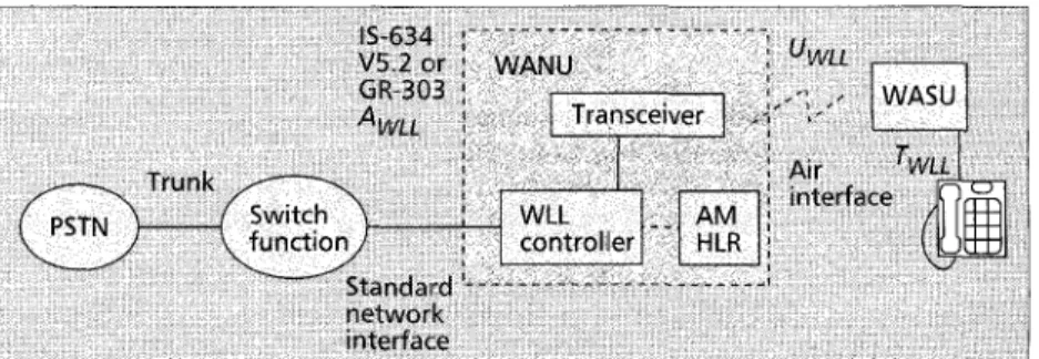
A simplified version of the TR-45.1 architectural reference model for WLL is shown in Fig. 1. In this figure, the wireless access network unit (WANU) consists of the base btatiori transceivers (BTS) or radio ports (RP), the radio controller (RPCU), an access manager (AM), and home location regis- ter (HLR), as required. The interface between the WANU and the switch is calledAWLL that can be IS-634,I IS-6S3,2 GR-303,3 VS.l,4 ISDN-BKI, and so on.
The air interface between the WANIJ and the user side is called UWLL. The WANU should provide for the authentication and privacy of the air interface, radio resource management, limited mobility management, and over-the-air registration of subscriber units (Sus). It may also be required t o provide Operation and Maintenance (OAMP), routing, billing and switching functions as appropriate or necessary. The WANU also provides protocol conversion and transcoding of voice and data. To support voice-band data and Group 3 Facsimile,
I IS-634 is an extension to the GSMA-interface specification to include support for other air interfaces such as PACS, IS-95, and IS-136, includ- ing support for mobile-controlled handover, .soft handover, and IS-41C
authentication a n d privacy protocols.
IS-453 is an ISDN-based A-inte&ce (radio system - PSCS) for 1800
MHz personal communiculions $witching cenler (PCSC) lo support PACS, J-LTTD-014, TL4 IS-661, a composite C D M A J T L I M nir interface compatibility standard for personal communications in 1.8-2.2 GHz for licensed and unlicensed applications or omnipoint. J-STD-009, - I 0, -I1 IS-134, J-STD-007 GSM, J-STD-008 IS-95, and J-STD-015 make up Q W-CDMA air interface compatibility stundard,for 1.85-1.99 GHz PCS applications.
Bellcore GR-303 is a multi-TI interface to a digital switch to support
POTS, ISDN, and special lines such as coin-operated phones. ITU-V5.1 arid V5.1 are the interiiatiorial equivalent to GR-303.
an interworking function (IWF) may also be required.
The TR45.1 reference model combines the BTS and the RPCU or base station con- troller (BSC) within a single functional net- work element, i.e., the WANU. In practice these devices may not be colocated. In the GSM network reference model, the interface between the BTS and the BSC is specified as
the A-bis interface. However, even in GSM Figure 1 . TR-45 wireless local lo40p reference model. this is not a well defined standard and imple-
m en t ati o n s a r e proprietary. T h e transmission backhaul a line p e r subscriber with i n 0 c o n c e n t r a t io n a t t h e A w L ~ between the base station and the switching system can be interface in the TR.45 reference model. The radio system leased lines, cables, or microwave [ 3 ] . Compared with the supports both fixed and mobile subscribers. However, mobil- leased lines and cable approaches, microwave has the advan- ity is limited to the areas served by a single WLL controller; tages of speed and flexibility in deployment, and rights of way wi d e - a r e a r o a m i n g is n o t s u p p o r t e d . T h e access when crossing third-party property is not an issue. On the managerihome location register (AM/HLR) handles authen- other hand, when deploying microwave, consideration must be tication and privacy. The maximum data rate supported on made for frequency availability, tower height restrictions, and the interface DSO is 56 kb/s; clear channel data, at 64 kb/s, the limitations of antenna size. Furthermore, the installation c a n n o t b e s u p p o r t e d . Mobility m a n a g e m e n t signaling should consider future obstructions that may affect the radio between RPCU and AM/HL,R may use any available trans- path (e.g., new buildings, tree growth, and so on). port (e.g., TCP/IP, X.25, etc.). Alternatively, the services and
The wireless access subscriber features can be supported by the
unit (WASU) provides an air HlLR o r a n AI N service control
interface toward the network and p a i n t ( S CP ) . T h e a r c h i t e c t u r e
a “traditional” interface TWLL to shown in Fig. 2 takes advantage of
the subscriber. This interface the AIN capabilities of the switch.
includes protocol conversion and The subscriber data bases reside
transcoding, authentication func- in the HLR. Features supported
tions, local power, OAMP, dual by the system are not the same as
tone multi frequency ( D T M F ) , t h e f e a t u r e s s u p p o r t e d by t h e
dialtone, and RJ-11 functions. A switch. wid e-are a r oam in g a n d
modem function may also b e mobility can b e su ppor ted . T h e
WLL controller uses existing call control and mobility management data so that analog signals such as
dat a and fax can be transported protocols. Mobility management
over the air digitally and recon- protocol between the Access Man-
structed by the IWF in the network. The TwLL interface can ager and the VLR may use lSDN Non-Call Associated Sig- be RJ-11 or RJ-45. An O ~ L L interface is defined to provide naling (NCAS) SS7 Transactions Capabilities Application
the OAMP interface to the WLL system. Part (TCAP), or other transport options. Mobility manage-
In this reference model the switching fabric (SF) is con- ment protocol between the WLL controller and the AM may sidered outside the scope of the TR-45 WLL Ad Hoc Group. use any available transport options [4].
This switch can be a digital switch with or without Advanced As mentioned above, in order for the air interface to pass Intelligent Network (AIN) capability, an ISDN switch, or a voiceband data and Group 3 Facsimile, a network data IWF is mobile switching center (MSC). In general, the WLL fea- usually required. Figure 3 gives a general view of the network tures and services can be those supported by the switch as is architecture for supporting intenvorking of these wireless and shown in Fig. 3 . The interface between the radio system net- wireline data services. One approach that has been described work elements and the non-AIN digital switch can be via a in detail is to uise X.25 o n ISDN B- or D-channels for the GR303 interface with robbed bit signaling allowing WLL to intermediate network and to assume that the remote network interface with any end office digital switch. The WLL ser- is the PSTN [SI. The radio access system refers to the radio vices are transparent to the switch, and the subscriber data devices and the (non-switched) wireline backhaul necessary to bases reside in the switch. All switch-based services can be connect the radio ports or base stations to their controllers. supported. The switch sees a logical line appearance, that is, The controllers are connected via an intermediate network to the data IWFs. T he IW F is needed t o convert required to support voice-band
the HLR, ___ - - - Radio access Intermediate Remote n e t w o r k _ _ ._ - _ _
Figure 3. Generalized network architecture for wireless-to-wireline data inter-
working.
the digital data on the air interface to a form suitable for transmission in the other networks. This may include rate adaptation and the termi- nation of a specialized error and flow control radio link protocol. The IWF must also be on a network from which the desired data application (represented as a “host”) is reachable. The wire- line network on which the IWF and host reside is called the remote network [5, 61.
The Wireless Local
Loop
Technologies
The WLL systems are typically based on one of the following four technologies [4, 21.
Satellite-Based Systems - These systems provide telephony services for rural communities and isolated areas such as islands. Satellite systems a r e designed for a Gaussian or Rician channel with K factor greater than 7 dB. These systems can be of two types:
Technology designed specifically for WLL applications 0 Technology piggybacked onto mobile satellite systems as an
adjunct service
Of these, the former offers quality and grade of service comparable to wireline access, but it may be expensive. The latter promises to be less costly but, due to bandwidth restric- tions, may not offer the quality and grade of service compara- ble to plain old telephone service (POTS). An example of a satellite based technology specifically designed for WLL is the HNS telephony earth station (TES) technology. This technol- ogy can make use of virtually any geostationary earth orbit (GEO) C-band or Ku-band satellite. Satellite technology has been used to provide telephony to remote areas of the world for many years. Such systems provide an alternative to terres- trial telephony systems where land lines are not cost effective or where an emergency backup is required.
There are many proposed systems for mobile satellite ser- vice, including the Inmarsat International Circular Orbit ( I C O ) system, I r i di um, G l o ba l s t a r , Odyssey, American Mobile Satellite Corporation (AMSC), Asia Cellular Satellite (ACeS), and Thuraya mobile satellite system. These systems are specialized to support low-cost mobile terminals primarily for low bit rate voice and data applications. Fixed applica- tions are a possible secondary use to mobile applications. There is a great deal of difference between these systems, especially when considering the orbit and the resultant prop- agation delay. The number of satellites and the propagation delay pose very different constraints on system design, so that there is no true representative system. For example, GEO satellite systems are not required to support handover even for most mobile applications. Mid-earth orbit (MEO) and low earth orbit (LEO) satellite systems require handover capability for all fixed and mobile applications because the satellites are in motion relative to the earth’s surface even when the terrestrial terminal is fixed. This can be problematic if the handover is supported in the switch because mobile switching centers (MSCs) support sophisticated mobility functions such as link handover, but do not typically support ordinary switching functions such as hunt groups, for exam- ple, which are highly desirable in a WLL system.
Cellular-Based Systems - These systems provide large power, large range, median subscriber density, and median circuit quality WLL services. Cellular WLL technologies are primari- ly used to expand the basic telephony services. Typically, they operate in the mobile frequency bands at 800-900 MHz, 1.8- 1.9 GHz, and sometimes at 450 MHz or 1.5 GHz [7].
This approach offers both mobility and fixed wireless access from the same cellular platform. For relatively sparse- ly populated rural and even urban settings, WLL technolo- gies based on existing cellular systems can be economical and rapidly deployable. Telecommunications Industry Asso- ciation (TIA) group TR.45 is considering IS-136 (US Digital TDMA), IS-95 (US Digital CDMA) and PCS-1900 (GSM) based systems for WLL. These systems are all optimized for cellular telephony, that is, for a Rayleigh fading channel with millisecond fade durations and with 5-10 ms of delay spread. They include much sophisticated technology (and therefore overhead bandwidth) not necessarily required for the WLL application. The resultant limited user bandwidth represents a fundamental limitation of such systems for WLL. However, the resultant coverage areas of the base stations is a more
than compensatory trade-off, especially in meeting voice and low bandwidth data needs. The HNS E-TDMA system [SI is a derivative of IS-136, modified specifically for WLL. It is the first cellular based system deployed for WLL and, as a result, is mature in terms of the features and service capabil- ities it supports.
As mentioned before, cellular systems are optimized for high-tier coverage. Support for mobiles traveling in excess of 100 mph and cell sizes up to 10 mi in radius is required. To achieve t h e above goals, extensive signal processing is required, which translates into high delay, high overhead and low user bandwidth.
These systems are not well suited to deployment indoors and in picocells. Additional complexity of the air interface with the same low user bandwidth is required. As an example, the Global System for Mobile Communications (GSM) uses high overhead forward error correction (FEC) with high delay (100-600 ms) intra-burst interleaving and equalization (train- ing sequence required) to correct for high fade rates. Block coding is also employed. The result is low user bandwidths, typically limited to 9.6 kb/s data rates. In developing coun- tries, such data capability limitations can be more than ade- quately c o m p e n s a t e d by t h e large coverage a rea s a n d consequent rapid deployment.
Low-Tier PCS or Microcellular-Based Systems - These sys-
tems provide low power, small range, high subscriber density, and high circuit quality WLL services. These technologies are considered to facilitate rapid market entry and to expand the capacity of the existing infrastructure. They a r e typically operated at 800 MHz, 1.5 GHz, 1.8 GHz, and 1.9 GHz fre- quency bands.
Compared with the cellular-based WLL, more base sta- tions are required to cover the same service area. Operators may consider low-tier WLL technologies when an existing infrastructure is in place to support backhaul from many base stations to the switch, or when wireline-like services and quality are essential. Microwave backhaul should be seriously considered to reduce the transmission cost. For densely populated urban environments, WLL technologies based on existing low-tier PCS radio technologies, by sup- porting higher user bandwidths, can offer features and quali- ty more commonly associated with conventional wireline access. low-tier systems such as PACS and PHS are designed to operate in a Rayleigh channel and can tolerate intermedi- ate delay spreads up to 500 ns. The basic user channel is typ- ically 32 kbls, with aggregation possible for much higher user bandwidths. The ANSI standard PACS system was designed specifically to support WLL, in addition to supporting limit- ed mobility, up to 40 mph [9]. Low-tier PCS and high-tier cellular air interfaces intended for WLL can be connected to conventional switches and do not require an MSC. Overlap- ping coverage areas and support of limited handover between neighboring base stations or radio ports is desirable in WLL systems as it improves the ability to perform maintenance, increases the robustness of the system, improves blocking statistics and provides for alternative access during excep- tional propagation activity. Such limited handover can easily be supported by a radio port or base station controller and need not have any impact on the switch. Low-tier technolo- gies, such as DECT, have been studied for their potential use for WLL. In general, such technologies were designed for an indoor Rayleigh channel with delay spreads less than 100 ns and picocellular coverage areas. Repeaters are used to compensate for small coverage areas, but this technique cuts into the overall capacity of the system. The small range, however, limits the delay spread impairment. Such systems
are not discussed in this article. For a good discus- sion of t h e application of D E C T technology for WLL, see [lo].
Fixed Wireless Access Systems - These systems are proprietary radio systems designed specifically for fixed wireless applications, which may or may not be extensible to PCS or cordless. The primary disadvan- tage of the cellular approach is its limitation on toll- quality voice (new toll-quality vocoders designed for cellular technologies may eliminate this problem), and signaling transparency. The primary disadvantage of low-tier PCS and microcellular approaches is their range. Nonstandard fixed wireless access (FWA) technology can address these issues and become more efficient. Such systems include the Interdigital TDMA system, which is a Bellcore standard; the new broadband CDMA standard by Okidata, which is a TR.45 interim standard from the Joint Technical Committee (JTC); and the Interdigital broadband CDMA technology, which is proprietary. FWA sys- tems for zonal areas are designed to cover the local telephone area directly from the PSTN switches. The systems for rural areas provide connection at the remote ends of rural links to the end users. (The sys- tems usually replace part of the loop distribution and part of a very long drop.)
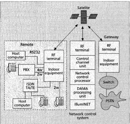
Figure 4. TES quantum topolo@
ported by WLL technology. User data rates over 9.6 kbls are considered optional by TR.45 because higher data rates are difficult for the cellular air interface standards for which TIA is responsible. However, it is not the intent of the Ad Ho c WLL Group to preclude non-TIA standards. From a service provider perspective, 28.8 kbls voiceband data, and ISDN-BRI data are desirable WLL service offerings. Additional WLL services include two-way short message service, D-channel packet service, Ethernet interface, dialed 64-kbls data port, X.25, 2-line senice, virtual second line, and power-on regis- tration of subscriber units.
Service Descrip fio
n
A TIA Ad Hoc group in TR.45.1 is drafting standards for WLL [11], including the interface between the radio equip- ment and the local switching fabric, the interface t o the operations system, and the radio air interface between the subscriber unit and the network radio port. They are also defining a set of standard services, custom calling features, and custom local area signaling services (CLASS) [12] fea- tures that should be supported by a WLL system. Desirable custo m calling f e a t u r e s i n c l u d e : call waiting, call call forward/unconditional, and three-way calling. In addi- tion to these important features, TR-45 has identified sev- era1 o p t i o n a l f e a t u r e s , including s p e e d dialing, a d d e d directory number with distinctive ringing, and business-like services such as multiline custom calling features. Desirable CLASS features include customer-originated trace, auto- matic recall, automatic callback, calling number delivery, and voice mail.
T h e WLL radio should support Centrex business ser- vices, including call coverage features such as hunt groups, call forwarding, voice mail service, and attendant service; call handling such as call transfer, conference calling and call park; convenience features such as speed calling, auto- matic dial, ring again, and busy override; and calling line I D . Centr ex dialing plans, e n d - u s e r m a n a g e m e n t , line restrictions, authorization codes, virtual access to private networks, station message detail recor ding, and direct inward dialing should also be supported. In addition, WLL systems should provide truck circuits supporting required interfaces for private branch exchanges (PBXs). Key tele- phone system (KTS) lines, and coin, credit card, and debit card telephones are all applications that should be support- ed by WLL technology.
Since the user information is transmitted over the air, com- munications privacy should also be provided. TR-45 cites V.22 (1200 b/s), V.22 bis, V.27 (4800 b/s), V.29 (9600 b/s), and Group 3 facsimile as required voiceband data rates to be sup-
fonvardlbusy, call forwardldefault, call forwardlno answer,
Examples
of W l l
Products
In this section, several WLL systems are described to illustrate WLL technologies.
HNS
Terminal
Earth
Station Quantum System
The HNS terminal earth station (TES) product is[13] used for the Intelsat network to provide remote access telephone ser- vice, I n total t here are approximately 100 T E S networks worldwide, in addition to the Intelsat network, and more than 10,000 remote site stations. The TES system is a satellite- based telephony and data communications network providing mesh connectivity between multiple earth stations. The system provides call-by-call demand-assigned multiple access (DAMA) circuits and preassigned circuits, via single hop sin- gle channel per carrier (SCPC) communications paths between earth stations. It supports both public and private networks, and is capable of operating with any telephony interface from individual subscribers t o toll switches and major gateways. The network architecture for TES is shown in Fig. 4. The TES network elements can be mapped into the TR-45 functional architecture model in Fig. 1.
An outdoor R F terminal and antenna plus indoor IF and base- band equipmeint performs the WASU functions. Several stan- dard TES subscriber unit models are available. High-power amplifier ( H P A ) power options include
5,
10, and 20 W for C- band and 2,5,
8, and 16 W for Ku-band. A small reflectorI
,
I
I .
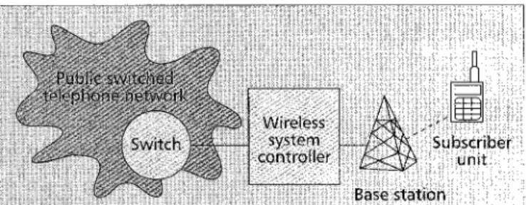
Figure 5 . The Lucent wireless subscriber system architecture.
communicate with each other and the network control sys- tem (NCS) using virtually any Ku- or C-band satellite, using single channel per carrier access to the satellite.
* The air interface employs quadrature phase shift keying (QPSK) or binary phase shift keying (BPSK) modulation, depending upon the user information and coding rates. FEC is provided at rate 112 or rate 314. Scrambling is used to spread the transmitted energy across the satellite channel bandwidth. Differential coding resolves phase ambiguity in the demodulated signals. Voice is coded using 32 kbls adap- tive differential pulse code modulation (ADPCM) (ITU-T G.721) or 16 kbis low delay-code excited linear predictive (LD-CELP) (ITU-T G.728).
The terrestrial interfaces toward the user which are sup- ported by TES include four- and two-wire ear and mouth (EM) or single-frequency (SF) inband signaling, RS-232, RS-449, and V.35 data interfaces. As can be seen from the figure, single-line versions supporting two-wire, RS-232, and ISDN interfaces are provided. In addition, multi-line access to a PBX can also be supported. The TES ISDN
ear th station provides 56 kb/s pulse coded modulated (PCM) voice.
The WANU equipment logically includes the satellite, ter- minal equipment, and NCS. Voice calls and asynchronous data calls can be made on demand under the control of the centralized DAMA processing equipment of the NCS. Satellite channels for user information are allocated only for the duration of these connections.
TES supports telephony, synchronous and asynchronous data, facsimile, ISDN BR I data, and E l and T 1 trunking between remote terminals anywhere in the system. Voice and data traffic is transferred directly between remote terminals, not via the NCS, to minimize the delay using a single satellite hop. Features and services are based on the remote PBX rather than on the centralized PSTN interface, which is an El or T1 trunk.
lucent Wireless Subscriber System
Lucent Wireless Subscriber System (Lucent WSS) is a cellu- lar-based WLL [14]. This system typically supports 800-5000 subscribers p e r switch contr olled a r e a ( t h e
capacity can be enhanced with a more powerful processor). The system architecture is described as follows (Fig. 5).
The subscriber unit is cellular system (i.e., AMPS) compilable, which communicates with the base station using the EIAITIA-553 air interface (FDMAIFDD at the 824-849MHz a n d 869-894MHz frequency bands). T h e capacity of the subscriber unit is a single tele- phone line.
The base station is a standard Lucent AUTO- PLEX System 1000 Series 1 Cell Site. The coverage area of a base station ranges from 12 Km t o 40 Km. T h e capacity of t h e base station can be up to 96 channels. T he base station contacts the subscriber unit by the air
interface and connects to the wireless system controller (WSC) by the T 1 line (the basic 24-channel 1.544 Mbls pulse code modulation system).
* The WSC connects to a switch (central office) of the PSTN using either analog trunks or T11El digital multiplexed trunks. The call control is done by R 1 or R2 in-band sig- naling, and the OAM (Operations, Administration and Maintenance) signaling is done by SS7 or X.25. In the call setup, the WSC will validate the subscriber unit by its elec- tronic serial number.
O th e r cellular-based WLL systems include the Alcatel A9500 (based on GSMIETACS), the Hughes GMH 2000 (E- TDMA, to be described in the next section ), and the Siemens system (based on GSM and DCS BOO), among others.
HNS E-TDMA
E-TDMA [2] is an extension to the IS-136 TDMA standard that provides support for WLL with increased capacity and improved network performance while maintaining the large coverage area feature of other cellular standards.
E - T D M A offers a choice of subscriber unit platforms including single subscriber units (SSU) and multiple subscriber units (MSU) capable of supporting up to 96 lines, depending on the subscriber traffic load and MSU provisioning. The sin- gle subscriber units support high capacity digital voice, fax, and data transparently using a standard RJ-11 interface, and enables multiple terminal connections as simple extensions on a single access unit or per directory number. Such units are appropriate for locations with low population densities such as residences and small businesses. Multiple subscriber units pro- vide access to the WLL system in areas of high population densities such as hotels and apartment buildings. MSU and radio resources are allocated on a call-by-call basis, thereby reducing the required hardware. Operations and maintenance of both SSUs and MSUs are supported by a full set of remote terminal diagnostic protocols t o assess performance and respond to end-user issues. Over-the-air activation protocols are also supported to improve system installation. The system supports software downloads to subscriber units to take full advantage of system upgrades remotely.
The E-TDMA base station provides an improved control channel to dynamically assign channels and time-slots t o active speakers. By automatically accounting for unexpected or changing interference conditions, adaptive or dynamic channel assignment can increase the capacity of a cellular radio technology [2] over centrally engineered, fixed and static assignment. A 5 kbls rate voice coder is also used which, by itself, more than doubles the capacity over IS-136. Finally, the implementation of discontinuous transmission (DTX) along with digital speech interpolation (DSI) means that both the
base station and the subscriber station transmit only when speech is present (about 40 percent of the time), thus sharing the radio resource effectively with other users. Because of these design elements, E-TDMA has a capacity advantage of between 7 and 17 percent over the benchmark AMPS, depending on the per- base-station channel pool size and other factors. By comparison, IS-136 has a capacity approximately three times greater than the capacity of AMPS, and GSM has a capacity approximately two to four times greater than the capacity of AMPS. E-TDMA supports a wide variety of country variant signaling. Tones and line signaling variations are software programmable, and in a number of cases can be set via system parameters. Both 16 kHz metering and Polarity reversal signaling mecha-
nisms for pulse signaling can be supported, if they are gener- ated and supported by the switching system. Thus, E-TDMA can interface with a wide variety of metering and public pay phone equipment. €INS-configured E-TDMA can interface to
a mobile switching center, when both mobile and WLL appli- cations need to be supported, or a class 5 end office switch, when both WLL and wireline POTS, with full feature trans- parency, need to be supported. Depending on the subtending switching equipment, E-TDMA is capable of supporting virtu- ally all of the vertical features and CLASS features recom- mended by TR-45, as listed above, including call waiting, call forwarding, conference calling, and so on.
The main strengths of cellular-based WLL systems over low-tier PCS based WLL systems include coverage, speed of deployment, and spectrum efficiency. The fundamental disad- vantage is the limited range of available user bandwidth. This trade-off implies a market for both system types. Currently, E- TDMA systems for WLL applications are installed in nine countries with a potential aggregate capacity of up to one mil- lion subscriber units.
The
PACS
WLL
System
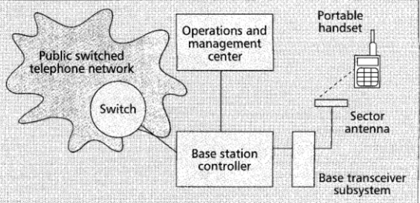
The ANSI standard personal access-communications system (PACS) WLL system [9] is a low-tier PCS-based WLL. The low power PCS technology supports high circuit quality (32 kbls voice coding) and low latency data with high user band- widths. The system architecture is illustrated in Fig. 6.
low-tier technologies for PCS typically rely on antenna diversity of one form or another to accommodate slow to moderate fades. Strategies include TDD diversity, pre-selec- tion diversity, and switched antenna diversity. No equalization or F E C are required; therefore, the full bandwidth of the channel is available for user information. PACS is designed to cover a broad range of venues not optimally served by typical cellular systems, including high density WLL. PACS has fea- tures that set it apart from other PCS and cellular standards. For example, PACS supports both public and private key authentication and privacy. It operates in both FDD and TDD mode, and can interoperate across a wide variety of public and private networks in licensed and unlicensed spectrum. It has a rich suite of data protocols, including packet and circuit protocols. It spans a wide range of venues from large outdoor microcells to indoor picocells.
T h e r e a r e two types of user terminals in PACSIWLL:
portable handset (subscriber unit) and fixed access unit. The
fixed access units convert the radio signal to an RJ-11 interface signal to the customer premises equipment. The user terminal communicates with the radio port following the JTCiPACS air interface (TDMITDMA at the 18.50-1910 MHz and 1930-1990 MHz frequency bands). The maximum transmit power is 200 mW and the average power is 25 mW. No echo canceller is required. The capacity of the handset is single line.
Figure 7. The Qualconzm QCTel architecture.
The radio port (RP) corresponds to WANU transceiver
units in the TIA architecture, and can support eight radio channels. T h e coverage a r e a of a R P is 0.5-2 km for t h e portable handsets and more than 2 Km for the fixed access units. The RP connects to the radio port control unit (RPCU) by E l , T1, HDSL, or DSL technologies. The maximum trans- mitter power is less than 10 W. Using HDSL, the RPs can be powered by the RP CU out to 12 kft at 130 Volts. The R P connects to the IRPCU by the T1 interface.
The RPCU provides management and control functions between the RP and the PSTN. Several RPCUs are connected t o a switch by o n e o r m o r e ( u p t o 120) ISDN-BRIs. T h e RPCU connectis to the operations and maintenance center (OMC) by X.25. The RPCU performs call control functions and the user aut henticationienciyption functions, and reports monitoring results to the OMC.
Other low-tier-based WLL systems include DECT-based systems such as the Alcatel A4220, theMotorola DRA 1900, the Siemens DIECTlink, the Lucent SWING, the Ericsson DRA 1200, and CT2-based systems such as Orbitel Linktel, Dassault Easynet, and the Nortel Proximity “L.”
Qualcomm
QCTel
Qualcomm’s QCTel CDMA WLL System is an FWA WLL [14]. A basic six-sector QCTel system may support 24,000 sub- scribers. The QCTel technology supports 8 kbis voice and up to 7.2 kbis data rate. QCTel supports limited mobility, and the subscriber unit (:an be a portable handset. The system archi- tecture is described as follows (Fig. 7).
The handset communicates with the base station transceiv- er using the IS-9’6 air interface (CDMNFDD at the 800 MHz, 900 MHz, and 11.8-2.2 GHz frequency bands). The handset can support multiple lines. The transmit power is 2 W (with power controlled).
The base transceiver station (BTS) communicates with the handset using the IS-95 air interface. The maximum transmit power is 50 W. The cell range is 25 km. The capacity is up to 45 voice channels. Up to 20 BTSs may be colocated with the base station controller (BSC) at the central office. Or 30 BTSs per area may be connected to a BSC using the T l i E l technol- ogy (up to three areas).
The BSC is collocated with a central office, which connects to a switch of the PSTN using T1, El, T3, or E3 digital multi- plexed trunks. The call control is done by R2 in-band signal- ing, and the OMC signaling is done by SS7 or X.25.
Other fixed wireless access WLL systems for zonal areas include CDMA-based systems such as the DSC Airspan, the Granger CD20010, the Siemens CDMAlink, and TDMA-based systems such as the Jenoptic FAS and Nortel’s Proximity ‘L‘ (TDMA).
T h e systems for rural a rea s include t h e Alcatel 9800 (TDM) and TDiMA-based systems such as the SR Telecom SRS00 and the TRTiPhillips IRT.
s
rY
WLL provides two-way calling services to the stationary or "fixed" users, which is intended to replace its wireline coun- terpart. To compete with other local loop technologies, WLL should provide sufficient coverage and capacity and high cir- cuit quality, and offer efficient data services.
Today, there are almost 100 wireless WLL systems (either trials or commercial systems). The WLL market is expected to grow to US$7.6-10 billion by the end of the century. Northern Business Information expects that an average of six million WLL lines will be added annually, and by the end of 2000,40 percent of the WLL lines will be in the Asia-Pacific region, 25 percent will be in Latin America, and 20 percent will be in Ea ste r n Eu ro p e . In summary, WLL has t h e po t e nt i a l t o become the major loop technology if its cost can be competi- tive with its wireline counterpart.
References
[ I ] Y.-B. Lin, "Wireless Local Loop," /€E€ Potentials, Aug/Sept 1997. [2] A. R. Noerpel, "WLL: Wireless Local Loop -Alternative Technologies," [3] S. Little, "Going Wireless on the Transmission Side," Telecom Asia, vol. [41 M. Couesnongle, "Communications International," Telecommun., 1996, [5] D. Harasty, et al. "Architecture Alternatives for Wireless Data Services: [6] Bellcore, "WACS Protocols Supporting Wireless Data Services," Tech. [71 S. J. Sampson, "Choosing the Right Wireless Loop," Telecom Asia, vol.
[8] S. Kay, "E-TDMA," Cellular Business, 1992, pp. 16-1 8.
191 A. R. Noerpel, Y.-B. Lin, and H. Sherry, "PACS: Personal Access Communica- tions System - A Tutorial," /€€€Pers. Commun., June 1996, pp. 32-43. [IO] M. Zanichelli, "Cordless in the Local Loop," Cordless Telecommunica-
tions Worldwide, Walter Tuttlebee, Ed., London: Springer, 1997. [ l I ] TIA, "Ad Hoc Wireless Local Loop," Tech. rep. TR45, 1996.
[I21 Bellcore, "A Guide t o New Technologies and Services," Tech. rep. SR- Proc. /€FE PIMRC, 7997, Helsinki, Finland.
7, no. 9, Oct. 1996, pp. 30-40.
pp. 14-18.
Interworking with Voiceband Modem," /€€E NPC '94, 1994, pp. 16-18.
Rep. GR-2850-CORE, issue 1, 1994.
7, no. 9, Sept. 1996, pp. 24-29.
BDS-000828, 1993.
1131 "TES Quantum," Tech. rep. 1022896-0001, rev. B, Hughes Network 1141 R. C. Schulz, "Wireless Technology and PCS Applications," GLA lnt%, 1996.
Systems, 1996.
Additional Reading
[ l ] V. Varma and V. Panday, "Functional Architecture for PACS Wireless Local Loop System," ATIS, PACS Providers Forum., T I P I .3/96- 246R1, Jan. 27, 1997.
Biographies
ANTHONY NOERPEL (anoerpel@lando.has.com) i s an advisory engineer at Hughes Network Systems i n t h e Advanced Development Group. He i s responsible for the development of the Common Air Interface for Thuraya ,
a geosynchronous earth orbit mobile satellite system. He also contributes t o the development of third generation mobile satellite evolution. Prior t o 1995, he worked at Bellcore where he developed the PACS low-tier cellular air interface and system design. Prior t o 1984, he worked at Bell Laborato- ries in satellite communications. He has several patents and has published papers in areas ranging from antennas and propagation t o wireless com- munications network architectures and protocols.
YI-BING LIN ISM '961 (liny@csie.nctu.edu.tw) received his B.S.E.E. degree from National Cheng Kung University in 1983, and his Ph.D. degree in com- puter science from the University of Washington i n 1990. From 1990 t o 1995, he was i n t h e Applied Research Area at Bell Communications Research, Morristown, New Jersey. In 1995 he was appointed professor in the Department of Computer Science and Information Engineering (CSIE), National Chiao Tung University (NCTU). In 1996 he was appointed deputy director of the Microelectronics and Information Systems Research Center, NCTU. Since 1997 he has been chair of CSIE, NCTU. His current research interests include design and analysis of personal communications services networks, mobile computing, distributed simulation, and performance modeling. He i s a subject area editor of the Journal of Parallel a n d Dis-
tributed Computing, an associate editor o f the lnternational l o u r n a l in Computer Simulation, /€€E Network, and SIMULATION, an area editor of ACM Mobile Computing and Communication Review, a columnist for ACM Simulation Digest, a member of the editorial board of the lnternational Journal of Communications Systems, ACM/Baltzer Wireless Networks, and Computer Simulation Modeling and Analysis, program chair for the 8th Workshop on Distributed and Parallel Simulation, general chair for the 9th Workshop on Distributed and Parallel Simulation, program chair for the 2nd International Mobile Computing Conference, publicity chair for ACM Sigmobile, guest editor of the ACM/Baltzer MONET special issue on Person- al Communications, and guest editor for the /€E€ Transactions on Comput-