國立交通大學
資訊科學與工程研究所
碩 士 論 文
一 個 固 態 硬 碟 虛 擬 平 台 的 設 計 與 實 作
Design and Implementation of a virtual platform
for solid-state disks
研 究 生:李盈節
指導教授:張立平 教授
一個固態硬碟虛擬平台的設計與實作
Design and Implementation of a virtual platform for solid-state disks
研 究 生:李盈節 Student:Ying-Chieh Lee 指導教授:張立平 Advisor:Li-Pin Chang 國 立 交 通 大 學 資 訊 科 學 與 工 程 研 究 所 碩 士 論 文 A Thesis
Submitted to Institute of Computer Science and Engineering College of Computer Science
National Chiao Tung University in partial Fulfillment of the Requirements
for the Degree of Master
in
Computer Science
July 2011
Hsinchu, Taiwan, Republic of China
II 一個固態硬碟虛擬平台的設計與實作 學生:李盈節 指導教授:張立平 國立交通大學資訊科學與工程研究所 摘要 業界在對固態硬碟做雛形設計時,除了離線的靜態效能模擬之外,亦對線上 的即時模擬有很強烈的需求。本研究基於建構一個即時的模擬環境,可在作業系 統內造出一個虛擬磁碟,而對該虛擬磁碟的讀寫動作會即時地導入固態硬碟模擬 器,並由模擬器算出所需的快閃記憶體動作,接著由此環境產生對應之時間延 遲。此一模擬環境可讓使用者即時修改其固態硬碟的軟硬體設計,並立即以該虛 擬固態硬碟進行線上存取,而提供設計者更直覺的效能觀感,並可立刻進行架構 上的微調。此年度相關技術議題包括該模擬環境與作業系統互動的作業系統核心 架構,以及如何利用少量真實記憶體來模擬大容量的固態硬碟的技術。 關鍵字:固態硬碟,效能模擬,作業系統
III
Design and Implementation of a virtual platform for solid-state disks
Student:Ying-Chieh Lee Advisor:Dr. Li-Pin Chang
Department of Computer and Information Science National Chiao Tung University
Abstract
When prototyping the architecture and firmware of an SSD, we found that Industry also has strong demands for real-time (on-line) simulation in spite of off-line performance simulation. This project developed a real-time SSD simulation environment. Specifically, this simulation environment creates a virtual disk in the host operating system. Designers can read and write the virtual disk with ordinary applications, the virtual drive forwards the I/O requests to the SSD simulation tool, which computes how many flash operations and how much time these requests take, and then the virtual drive simulates the I/O latencies. This approach provides designs a more intuitive and responsive approach for prototyping the design of an SSD. The technical issues of this project year include the interaction between the host operating system and the virtual drive and a method to create a very large virtual disk with only a limited RAM overhead.
IV 誌謝 在交大的兩年研究所時光匆匆飛逝,這期間實在受到太多太多人的照顧,僅 以此篇誌謝表達自己的感謝。 最要感謝的是指導教授--張立平老師兩年來的指導,若沒有老師的指導,學 生無法完成這篇論文;老師的教導讓學生除了在研究方面有所獲得外,更在做人 處事方式上受益匪淺。 感謝晉廷、偉杰、義勛、莉君幾位學長姐,在我碩一期間幫助快速我融入實 驗室環境;晉廷的細心,偉杰的風趣,義勛的率直,莉君的大方,使得與你們相 處的一年當中,每天都很充實愉快。 感謝翊誠、玟蕙、薇涵幾位優秀的同屆同學,無論是課業、研究或者面對困 難的態度,從你們身上我真的學習到很多;而翊誠的幽默,玟蕙的慧黠,薇涵的 認真,都將成為我回憶的瑰寶,兩年來受你們關照了。 感謝文平、逸康、棟揚、柏翰、晨意幾位學弟妹,最後一年有你們的陪伴, 讓實驗室保持著良好的氣氛;文平的不懈,逸康的努力,棟揚的樂觀,柏翰的自 信,晨意的蕙質,每個人都散發著無窮的發展性,加油! 因為實驗室的大家,研究所生活才如此璀璨多彩,相信我們之間的情誼會長 久保持下去。 感謝在交大當中認識的朋友們,名單太長無法一一列舉;希望你們在未來都 能夠一帆風順。 最後,要感謝我最愛的家人們與女友彥婷的關懷,有你們在背後的全力支 持,我才得以完成學業。
V 目錄 1. INTRODUCTION ... ‐ 1 ‐ 2. HARDWARE/SOFTWARE SIMULATION ... ‐ 3 ‐ 2.1 Hardware Abstraction ... ‐ 3 ‐ 2.2 Firmware Abstraction... ‐ 4 ‐ 2.3 Configuration Example ... ‐ 5 ‐
3. VIRTUAL DRIVE: ON-LINE SIMULATION ... ‐ 7 ‐
3.1 Interacting with the Host OS ... ‐ 8 ‐
3.2 Metadata Identification ... ‐ 9 ‐
3.3 IO delay simulation ... ‐ 11 ‐
4. EXPERIMENT ... ‐ 15 ‐
5. CONCLUSION ... ‐ 18 ‐
VI
圖目錄
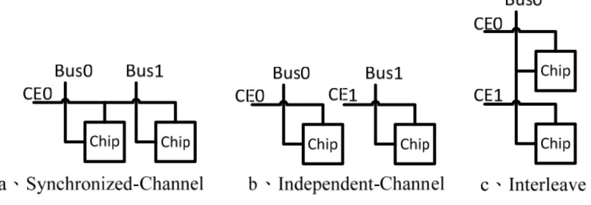
FIGURE 1SSDINTER-CHIP ARCHITECTURE ... ‐ 3 ‐
FIGURE 2OUT-OF-PLACEDATAPLACEMENT ... ‐ 4 ‐
FIGURE 3ABSTRACT FIRMWARE LAYER ... ‐ 5 ‐
FIGURE 4SSD VIRTUAL PLATFORM ON-LINE SIMULATION EVIRONMENT ... ‐ 7 ‐
FIGURE 5 KERNEL MODE AND USER MODE SYNC EVENT FLOW ... ‐ 8 ‐
FIGURE 6 DRIVER METADATA IDENTIFICATION RULE DATABASE CONCEPTION ... ‐ 10 ‐
FIGURE 7IO DELAY SIMULATION - STORE METADATA ONLY ... ‐ 12 ‐
FIGURE 8 INSTALLING OFFICE USING TWO DIFFERENT CHANNEL ARCHITECTURES OF SSDS ... ‐ 17 ‐
‐ 1 ‐
1. INTRODUCTION
Recently, flash-based solid-state disks (SSDs) start replacing traditional hard drives in mobile computers. Designing high performance SSDs is a very challenging task because of complexity of SSDs hardware architectures, and firmware algorithms. One practical problem that industry faces is how to combine hardware/software design options for the best performance under a specific niche market. So far, there are some off-line simulation tools [2] [1] [4] [3] can be used to test firmware and hardware combinations.
Because the existing off-line simulation tools are hard to use, it cause the long development and test cycle for SSDs designing. we found that industry has strong demands to reduce the modify-and-test cycle time. On the other hand, off-line simulation has a problem is that the trace files are collected from HDDs, the request interarrival time will subject to underlying storage device, if collect trace from a slower device, interarrival time will increase. so the trace files collected from HDDs can not express the real SSDs IO response.
This paper will present a On-line SSD simulation environment, and includes a fast hardware-software prototyping tool for SSD design, it
‐ 2 ‐
features a set of highly simplified programming interfaces and a rich collection of hw/sw design options. Specifically, this simulation environment consists of two parts, sim- engine and virtual drive, the sim-engine calculates the IO delay of the SSD, and the virtual drive can creates a virtual disk in the host OS. Designers can read and write the virtual disk with ordinary applications, the virtual drive forwards the I/O requests to the sim-engine, which calculates how many flash operations and how much time these requests take, and then the virtual drive simulates the I/O latencies. This tools aims at reducing the cost of debugging and help to find out the best design without lengthy trial-and-error cycles.
There was some technical challenges of virtual platform: a) the sim-engine how to provides a simple and uniform ssd HW / SW abstraction method, let designers can change the designing of SSDs easily. b) how the virtual platform to interacts with the OS, achieve the capability of virtual disk. c) how the sim-engine calculates the IO delay accurately, and simulate the IO delay by the virtual drive. d) how the virtual drive to creates a very large virtual disk with only a limited RAM overhead.
‐ 3 ‐
2. HARDWARE/SOFTWARE SIMULATION 2.1 Hardware Abstraction
The SSDs HW-architectures as shown in Figure 1, we can see that the ”gang” is the channels conected by same chip enable line(CE), each channel must does the same read or write operation. If the channels without conected by same chip enable line, like the Figure 1(b), the each channel can does the read or write operation Independently. The ”interleve” is like the conception of pipeline of computer architecture, each chip can be operate the read or write command independently when other chips is busy in the same channel.
In our virtual platform, we used a timing engine to simulate parallel hardware operations, if a operations completed, it will notice other simulation modules. In the other words, the time of Repetition of parallel hardware operations are calculated only once.
‐ 4 ‐
2.2 Firmware Abstraction
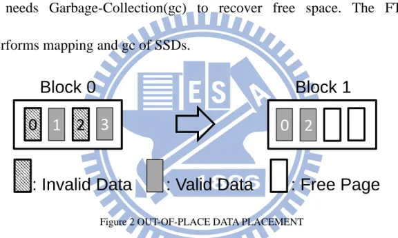
The minimum write unit of Flash memory is a page, but a page cannot be rewritable unless it be erase. But the minimum erase unit of Flash memory is a block, for performance reasons, the SSDs use out-of-place data placement method, as shown in Figure 2, and this method have to use the mapping table to record information of data, and it needs Garbage-Collection(gc) to recover free space. The FTLs performs mapping and gc of SSDs.
Block 0
Block 1
0 2
0
1
2
3
: Invalid Data
: Valid Data
: Free Page
Figure 2 OUT-OF-PLACE DATA PLACEMENT
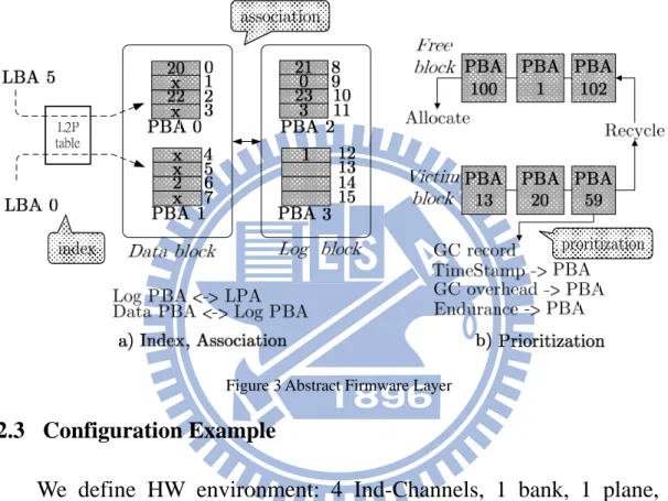
We designed a set of FW abstraction APIs in our virtual platform, and defined three abstract elements of FTLs shared, as shown in Figure 3. Here we show that how can we model the behaviors of FTLs using these primitives. There is a NK[6] FTL. As shown in Figure 3(a), the index service of FTLs is to deal address mapping, so we not only record the relationship bwtween logical block address(LBA) and phisical block address(PBA), but also have to record the relationship bwtween lofical
‐ 5 ‐
page address(LPA) and phisical page address(PPA). The association service represent the relationship between Data Sets of FTLs, for example, how many data blocks corresponds to a log block. As shown in Figure 3(b), the prioritization service is used to selected a victim block in GC.
association
proritization index
Figure 3 Abstract Firmware Layer
2.3 Configuration Example
We define HW environment: 4 Ind-Channels, 1 bank, 1 plane, 1 interleave level. And Flash Chip characteristics, shown as below:
NUMBER OF GANG = 1; CHANNEL PER GANG = 4; CHIP PER CHANNEL = 1; PLANE PER CHIP = 1;
hwAPI->SetupFlashChip(Chip Character);
About firmware, as shown in algorithm 1 the FW API can do: 1) if the write operation smaller then one page and this page was write before, we do read modify write. 2) write this page to log block, and use API
‐ 6 ‐
handle GC or get new log block. 3) modify index, tied logical page address and physical page address together. 4) group the logical page address and log block (association). 5) if have no free space, do GC.
Algorithm 1 FW API: BAST FTL for handle a page do oldWritePPAQueryIndex(pageindex); if operation ¡ one page size then *handle read modify write*/ end if while Write(1 page) < 0 do if (have no Current log block then DoGetOneF reeLogBlock(); ModifyIndex(pageindex, blockindex); else DoGarbageCollection(); ModifyIndex(pageindex, blockindex); end if AccessBlockQueryBlock(blockindex); end while ModifyIndex(pageindex, blockindex); AssignGroupUnit(pageindex, blockindex); if have no free log blocks then DoGarbageCollection(); end if end for
Compare the BAST FTL code with a truly SSD development platform. Use our fw API can reduced more then 75 percent of lines of source code.
‐ 7 ‐
3. VIRTUAL DRIVE: ON-LINE SIMULATION
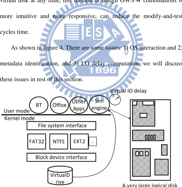
We proposed a conception of on-line simulation, as shown in Figure 4. There is a virtual drive in the kernel mode of OS, designer can create and control a virtual disk like use a real disk, unlike the user mode file system[8] only handle user data, virtual platform will produces I/O delay of the HW/FW combinations at virtual disk, designer can test and use virtual disk at any time, this method of design GW/FW combinations is more intuitive and more responsive, can reduce the modify-and-test cycles time.
As shown in figure 4, There are some issues: 1) OS interaction and 2) metadata identification, and 3) I/O delay computation. we will discuss these issues in rest of this section.
‐ 8 ‐
3.1 Interacting with the Host OS
As previously mentioned, we had design a HW/FW abstraction API in our virtual platform. For purpose to design SSDs HW/FW easily, this HW/FW abstraction API have to keep in user mode of OS.
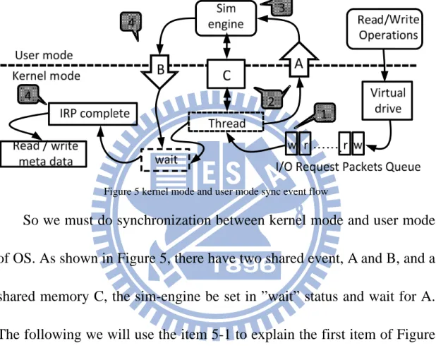
Figure 5 kernel mode and user mode sync event flow
So we must do synchronization between kernel mode and user mode of OS. As shown in Figure 5, there have two shared event, A and B, and a shared memory C, the sim-engine be set in ”wait” status and wait for A. The following we will use the item 5-1 to explain the first item of Figure 5, and so on. Virtual drive will received the I/O request packets(IRPs) from application, and put them to a queue, as shown in item 5-1, then use thread to handle this queue. thread put info of simulation required to the C and set A to notice sim-engine in user mode, as shown in item 5-2, then it be set to ”wait” status.
‐ 9 ‐
up and get info from C and start to simulation, and put the IO delay info in C. We wll calculate how may time to used to simulation and OS mode switch overhead, when simulation done, sim-engine will set B, as shown in item 5-4, and thread will start up and load the delay info from C and produces virtual I/O delay, and complete the IRP, as shown in item 5-5, then keep going to deal metadata. We will verified virtual I/O delay in experiments. About OS mode switch overhead, we will explain in section IV.
On the other hand, the sim-engine may also implement scheduling policies for out-of-order request completion.
3.2 Metadata Identification
In order to simulating a very large SSDs with limited RAM space, we proposed the conception of Metadata Identification.
The metadata is the data of data,on the other words, its index of data, and it is small portions among all the data, the file systems can works well with only store it’s metadata, and cause the disk Benchmark tools(IOmoter, ATTO, etc.) will not to verify the data write to disks when in benchmark, so those Benchmark tools can works in virtual disk with only store the file systems metadata.
‐ 10 ‐
For example, when we format a 250GB disk to a NTFS volume, the size of metadata of this disk is only occupy 74.46MB of storage space, so we can reduce RAM footprints of this SSD virtual platform by metadata identification method, Sivathanu[7] proposed a method to identify ”live data”, but this method is focus in data content identification, not metadata.
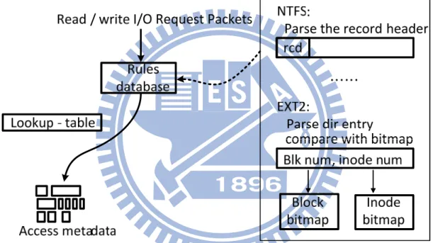
Figure 6 driver metadata identification rule database conception
To do Metadata Identification, a challenge is different file Systems has different structures, so we had implement a ”rules database” in our virtual drive, as shown in Figure 6, the rules database includes many metadata identification rules with file systems, through this database we can find and store the matadata of different File Systems. We will discuss tow samples rules of metadata identification methos with NTFS and ext2
‐ 11 ‐
in rest of this section.
In NTFS(New Technology File System) environment, the main metadatas is all store in the MFT(Master File table). First, in the disk boot sector content, we can have know that where is the MFT store in, and fortunately, every MFT entries is a ”record header”, and we can identify these records through parse the data content in or virtual drive, then we can store these records to maintain the NTFS execution well, as shown in Figure 6.
The previous work [9] just recognizes the metadata of fixed location of EXT2 file system, so it can’t identified ”directory i-node” in EXT2’s Block Group, because the directory of EXT2 is not stored in a fixed location. our ext2 metadata identification method can identify the directory of EXT2. As shown in Figure 6. First, we can parse the i-node data content, then compare i-node number with the i-node and block bitmap, if the i-node is a directory i-node, we store this metadata in the memory.
3.3 IO delay simulation
There are two problems about IO delay simulation: the HW time spending, and the OS timing overhead.
‐ 12 ‐
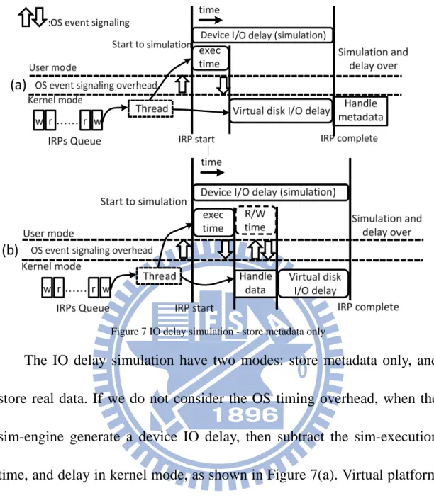
Figure 7 IO delay simulation - store metadata only
The IO delay simulation have two modes: store metadata only, and store real data. If we do not consider the OS timing overhead, when the sim-engine generate a device IO delay, then subtract the sim-execution time, and delay in kernel mode, as shown in Figure 7(a). Virtual platform can store real data, as shown in Figure 7(b), the device IO delay have to subtract sim-execution time and data handle time. The seek time of HDDs will break the virtual IO delay accuracy, can use ram-disk device to solve it. Cause the virtual platform used events signaling to synchronize sim-engine and virtual drive, it has some overhead of signaling of kernel mode and user mode. On the other head, the processes in user mode will
‐ 13 ‐
be schedule, the scheduler will trigger context switch between user processes, it may affects the virtual platform simulation accuracy.
To minimize the impacts of OS mode switch overhead and context switch between user processes, we use some methods to deal this problem. First, We get the processor’s time stamp counter(TSC) to calculate the cpu cycle time used to events signaling, in other words, we use a calibration phase to compute the event signaling overhead. Second, we put the delay of virtual platform in the OS kernel mode, to avoid the competition with user process. Third, we run the sim-engine with high priority, to avoid the virtual platform affected by context switch.
There are symbols denotation and methods for calculating virtual IO delay, as shown in Table 1.
Symbol Denotation tevent tex tbusdly tchipbsy tdviodelay
OS event signaling overhead. sim-engine execution time. bus delay time.
flash chip busy time.
device IO delay time (simulation).
The tevent and tex are calculated by TSC, and the treqdly is the cost time
‐ 15 ‐
4. EXPERIMENT
In this section, we have two partial of experiments, First is verify accuracy of the virtual platform, in this partial, we will compare the virtual platform with a real SSD. second is test the SSD HW and FW designing in the real disk workload. We do simulation validation by comparing the benchmark results (IOmeter and ATTO) of using our virtual platform and the real platform (i.e., GP5086) and performance results of installing Office using two different SSD designs.
We configure the virtual platform with the same HW/FW architecture of real platform in section ”Configuration Example” already. As shown in the following table, we can see the virtual platform virtual I/O delay error less then 5 percent, the reason of error is that the Program/Erase time of Flash memory chip will varies with the changes of temperature and voltage.
‐ 16 ‐
To test the our methods to deal events signaling overhead and context switch between user processes, we use FFT-z tool to Increase CPU utilization and test virtual platform, as shown in the following table. Cause the switch overhead is little effect, and virtual delay in kernel can reduce the impact of process schedule, the virtual platform in high stress environment can maintain virtual delay accuracy.
To comparing the performance of installing Office using two different SSD designs, we set the common environment of them: 32GB size, 256MB overprovision.
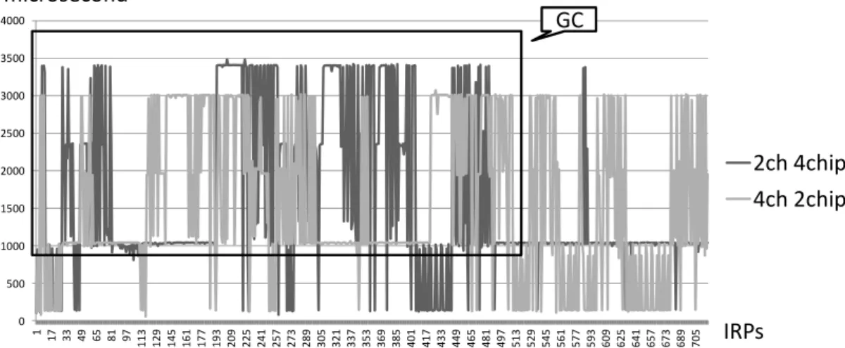
First, See the HW-arch of two different design, as shown in Figure 8. We define the chip number in 8, and change the channel number with 2 to 4. We can observed that if there has more channels, the data process more parallel, so it has lower response time in GC, but more channels will split the overprovision,
‐ 17 ‐
it will cause frequent GC.
0 500 1000 1500 2000 2500 3000 3500 4000 1 17 33 49 65 81 97 11 3 12 9 14 5 16 1 17 7 19 3 20 9 22 5 24 1 25 7 27 3 28 9 30 5 32 1 33 7 35 3 36 9 38 5 40 1 41 7 43 3 44 9 46 5 48 1 49 7 51 3 52 9 54 5 56 1 57 7 59 3 60 9 62 5 64 1 65 7 67 3 68 9 70 5 2ch 4chip 4ch 2chip IRPs microsecond GC
Figure 8 installing Office using two different channel architectures of SSDs
Then we will compare two different FW-design, NK 16:32 and FAST[5], as shown in Figure 9. We can see the the FAST cant limited log block associativity, so in GC, the FAST response time is higher than NK, means that in this workload FAST will makes SSD freeze.
0 200 400 600 800 1000 1200 1400 1600 1800 2000 1 11 21 31 41 51 61 71 81 91 10 1 11 1 12 1 13 1 14 1 15 1 16 1 17 1 18 1 19 1 20 1 21 1 22 1 23 1 24 1 25 1 26 1 27 1 28 1 29 1 30 1 31 1 32 1 33 1 34 1 35 1 36 1 37 1 38 1 39 1 40 1 41 1 42 1 43 1 44 1 FAST NK 16:32 IRPs GC microsecond
‐ 18 ‐
5. CONCLUSION
We present a virtual platform for solid-state disks, and design a abstracted HW/FW interfaces in user mode for easy to design SSDs, virtual platform can do on-line simulation for fast test-and-modify cycles. The virtual platform can store metadata only, and creates huge SSDs using limited RAM space, in experiment, we do Simulation accuracy is validated using real products, the timing accuracy error is less than 5 percent, ,and we comparing the performance results of installing Office using two different SSD designs.
‐ 19 ‐
6. REFERENCE
[1] N. Agrawal, V. Prabhakaran, T. Wobber, J.D. Davis, M. Manasse, and R. Panigrahy. Design tradeoffs for SSD performance. In USENIX 2008 Annual Technical Conference on Annual Technical Conference, pages 57– 70. USENIX Association, 2008.
[2] J.S. Bucy, J. Schindler, S.W. Schlosser, G.R. Ganger, et al. The DiskSim simulation environment version 4.0 reference manual. Technical report, Technical report cmu-pdl-08-101, carnegie mellon university, 2008.
[3] Youngjae Kim, Brendan Tauras, Aayush Gupta, and Bhuvan Urgaonkar. Flashsim: A simulator for nand flash-based solid-state drives. In Proceedings of the 2009 First International Conference on Advances in System Simulation, pages 125–131, Washington, DC, USA, 2009. IEEE Computer Society.
[4] Jongmin Lee, Eujoon Byun, Hanmook Park, Jongmoo Choi, Donghee Lee, and Sam H. Noh. Cps-sim: configurable and accurate clock precision solid state drive simulator. In SAC’09, pages 318–325, 2009.
[5] Sang-Won Lee, Dong-Joo Park, Tae-Sun Chung, Dong-Ho Lee,
Sangwon Park, and Ha-Joo Song. A log buffer-based flash translation layer using fully-associative sector translation. ACM Trans. Embed. Comput. Syst., 6, July 2007.
[6] Chanik Park, Wonmoon Cheon, Jeonguk Kang, Kangho Roh, Wonhee Cho, and Jin-Soo Kim. A reconfigurable ftl (flash translation layer) architecture for nand flash-based applications. ACM Trans. Embed. Comput. Syst., 7:38:1–38:23, August 2008.
[7] Muthian Sivathanu, Lakshmi N. Bairavasundaram, Andrea C. ArpaciDusseau, and Remzi H. Arpaci-Dusseau. Life or death at block-level. In Proceedings of the 6th conference on Symposium on Opearting Systems Design & Implementation - Volume 6, pages 26–26, Berkeley, CA, USA, 2004. USENIX Association.
[8] Jun Wang, Rui Min, Yingwu Zhu, and Yiming Hu. Ucfs-a novel user-space, high performance, customized file system for web proxy servers. IEEE Trans. Comput., 51:1056–1073, September 2002.
‐ 20 ‐
[9] Po-Liang Wu, Yuan-Hao Chang, and Tei-Wei Kuo. A
file-system-aware ftl design for flash-memory storage systems. In Design, Automation Test in Europe Conference Exhibition, 2009. DATE ’09., pages 393 –398, april 2009.