line first higher order mode. Dependence of the propagation characteristics on structural parameters and the effect of finite-conductor planes are analyzed. The propagation characteristics of the surface-wave-like modes are also discussed. In order to avoid inadvertent excitation of these surface-wave-like modes in antenna applications, the current and field distributions of the slotline first higher order mode and the surface-wave-like modes are compared and discussed. Excitation of the slotline first higher order mode was conducted by feeding the slotline with a coplanar waveguide and microstrip line. Experimental results show good agreement with our numerical results, and also confirm the existence of the slotline first higher order mode.
Index Terms— Higher order mode, leaky-wave antenna, slot-line.
I. INTRODUCTION
L
EAKY-WAVE antennas are better choices in the millimeter-wave frequency region due to some ad-vantages such as relaxed requirement of tolerance, low profile, structural simplicity, easy integration, and frequency scanning ability [1]. The leaky-wave line sources can be divided into two types according to their structures. One of them employs periodic structures, and the other uses uniform open waveguide. The common feature of a leaky-wave antenna based on periodic structures is the creation of space harmonics via periodic perturbations. These periodic perturbations include dielectric gratings [2], metal gratings [3], and slot array on the conductor plane of the image guide [4]. The common feature of a leaky-wave antenna based on a uniform open waveguide is the use of the operating frequency near and above the mode cutoff region [1]. These uniform waveguides include structures based on groove guide, nonradiative dielectric (NRD)-guide, and microstrip line.The uniform leaky-wave antennas are very suitable to be used as a line source of a two-dimensional scanning antenna array in which one direction is controlled by frequency and
Manuscript received July 15, 1996; revised July 2, 1998. This work was supported in part by the National Science Council under Grant NSC 85-2221-E-009-030 and under Grant NSC 84-NSPO-A-RDD-009-01.
J.-W. Sheen is with the RF Communication Systems Technology De-partment, Computer and Communication Research Laboratories, Industrial Technology Research Institute, Hsinchu, Taiwan 300, R.O.C.
Y.-D. Lin is with the Institute of Communication Engineering, National Chiao Tung University, Hsinchu 300, Taiwan, R.O.C.
Publisher Item Identifier S 0018-9480(98)08008-9.
theoretically and experimentally in [5]–[10]. In [5], exper-imental verification of a microstrip-line higher order mode leaky-wave antenna was conducted without an explanation of the physics underlying the design of the antenna. In [6] and [7], Oliner explained the physics underlying the leaky-wave antenna design constructed in [5] and presented analysis data for the antenna design. In [8], a groove guide with an asymmetrically located metal strip was proposed as a leaky-wave line source of phased arrays. It is a modification of the offset-groove-guide leaky-wave antenna [9]. In [10], space-wave leakage phenomena from higher order modes on various planar transmission-line structures with conductor sidewalls were investigated.
As discussed above, much attention has been spent on the application of the microstrip first higher order mode as a leaky-wave line source. However, there are few researches concerning the use of the higher order modes in other planar or uniplanar transmission lines. Therefore, the investigations of the slotline first higher order mode are motivated by developing a new low-cost millimeter-wave antenna. In certain applications, the use of the slotline may be required. For instance, combination of printed strips and slots in [11] and [12] creates a circular polarized antenna. Besides, the slotline is a uniplanar structure, which has certain advantages over the microstrip line in microwave integrated-circuit applications [13], [14]. To use the slotline first higher order mode as an efficient leaky-wave line source, the propagation character-istics, feeding efficiency, and antenna pattern must be fully analyzed. In this paper, we focus on the investigation of the propagation characteristics of the slotline first higher order mode. In Section II, leakage properties of the first higher order mode of the slotline with infinite-conductor planes and the geometric dependencies of the propagation properties of the slotline first higher order mode are presented. In Section III, leakage properties of the first higher order mode of the slotline with finite-conductor planes and the geometric dependencies of the propagation properties of the slotline first higher order mode are also presented. In Section IV, the properties of the undesired surface-wave-like dominant mode and their differences compared with the slotline first higher order mode are discussed. In Section V, excitation of the slotline first higher order mode are conducted by feeding the slotline with a coplanar waveguide (CPW) and a microstrip line. Measurement is also performed to validate our analysis. 0018–9480/98$10.00 1998 IEEE
Fig. 1. Dispersion curves of the constituent modes in the slotline with infinite-conductor planes.
II. THE FIRSTHIGHERORDERMODE INSLOTLINES WITH INFINITE-CONDUCTOR PLANES
The slotline with infinite-conductor planes and a magnetic-wall symmetry plane at the center of the slot is shown in the inset of Fig. 1. The conventional slotline mode assumes an electric-wall symmetry plane, while the first higher order mode assumes a magnetic-wall symmetry plane. Using the familiar spectral-domain method with appropriate deformation of the spectral-domain integration contour and choice of the branch cut to include the proper surface-wave pole and space-wave excitation [15], the propagation constants of the constituent modes in the slotline can be obtained. Fig. 1 shows the normalized propagation constants of the first higher order mode of the slotline, the surface-wave-like mode of the slotline and the mode supported by the surrounding structure. In order to explain the propagation characteristics presented here, we can view the cross section of the slotline as consisting of an inner region sandwiched between two identical outer regions, similar to what was done for the analysis of the open dielectric waveguide in [16] and [17]. As shown in the inset of Fig. 1, the inner region consists of an ungrounded dielectric waveguide and the outer regions consist of grounded dielectric waveguides. Guidance and leakage along the slotline can then be explained in terms of multiple reflections of surface waves supported by these waveguides. As shown in Fig. 1, the first higher order mode of the slotline does not evolve into a bound mode in the higher frequency region as that of the microstrip line. Rather, it lies in the surface-wave leakage region [15] in the entire high-frequency region with its propagation constant being complex and its phase constant smaller than that of the mode. The reason is that the effective dielectric constant in the inner ungrounded dielectric-slab region is smaller than that in the outer grounded dielectric-slab region. As the frequency is decreased, the propagation constant of the slotline first higher order mode decreases to be smaller than that of the free-space wavenumber as those of the higher order modes in all guiding structures. The mode leaks power into space waves as well as into surface waves in this frequency region. This is the frequency region in which the higher order mode can be used as a leaky-wave line source. When the frequency
Fig. 2. The electric-field distributions of the first higher order mode of slotline with infinite-conductor planes in the radiation region.
is further decreased, the normalized phase constant of the first higher order mode will rise again, and the normalized attenuation constant will become very large. However, the large value of the attenuation constant does not mean that the mode will leak more power into space waves and surface waves. Instead, as indicated in [7], [18], and [19], the mode is now in the cutoff region. Most of the power is reflected back into the feed line and very little power is radiated into the space wave.
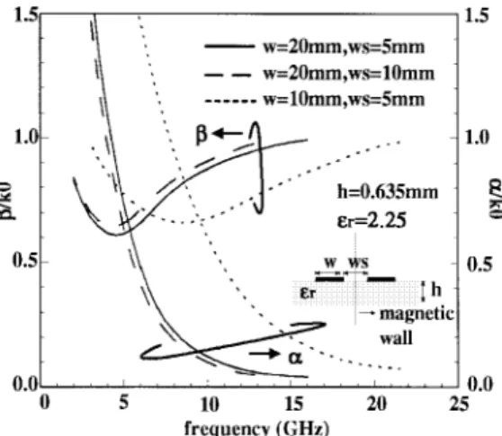
In Fig. 1, it is shown that the attenuation constants of the slotline are very large even if the first higher order mode is op-erated near the surface-wave leakage region. This phenomenon is different from that of the microstrip line first higher order mode. It is due to the fact that there is more power being leaked into the mode, which can be clearly observed from the electric field plot in Fig. 2. This results in a lower radiation efficiency in the radiation region since less power is radiated into space waves. This indicates that the slotline first higher order mode in the infinite-conductor plane cases is not suitable to be used as an efficient leaky-wave line source in antenna applications. Another effect that comes from the high value of the attenuation constants is that the phase constants are also larger in the radiation region. As shown in Fig. 1, they are very close to , the free-space wavenumber in the entire radiation region. The main beam directions are very close to the endfire direction in the entire radiation region. This will render the scanning range of angles narrower when frequency is changed since the main beam direction of the leaky-wave antenna is dominantly controlled by the phase constant. From Fig. 1, it is also shown that the radiation frequency region is much wider than that of the microstrip-line cases [15]. It is due to the fact that the propagation constants of the surface waves in the inner ungrounded dielectric slab is close to the free-space wavenumber, resulting in the effective dielectric constant of the inner ungrounded dielectric slab being close to one. Fig. 3 shows the variation of the first higher order mode with different slotwidths. Although the surface waves in the ungrounded dielectric-slab region is dispersive, the radiation band is almost linearly proportional to the width of the slot. The operational frequency of the leaky-wave antenna can easily be controlled by scaling the slotwidth accordingly.
Fig. 3. Behavior of the normalized phase constants and the normalized attenuation constants as a function of frequencies for the first higher order mode of the slotline with different slot widths.
Fig. 4. Dispersion curves of the constituent modes in the slotline with finite-conductor planes.
III. THEFIRST HIGHERORDERMODE INSLOTLINES WITH FINITE-CONDUCTOR PLANES
When we use the slotline as a leaky-wave antenna, the conductor planes are finite. After our investigation, we find that the first higher order mode of slotlines with infinite-conductor planes and that of slotlines with finite-infinite-conductor planes have very different propagation characteristics. Fig. 4 shows the normalized propagation constants of the first higher order mode of the slotline with finite-conductor planes, the surface-wave-like mode, and the and the modes supported by the outer ungrounded dielectric slab. Similar to what was done in Section II, we can break the cross section of the structure into constituent parts to discuss the propagation characteristics of the guided modes. As shown in the inset of Fig. 4, the cross section of the slotline with finite-conductor planes can be divided into constituent parts as: 1) an inner region consisting of ungrounded dielectric waveguide; 2) two intermediate regions consisting of grounded dielectric waveguides; and 3) two outer regions consisting of ungrounded dielectric waveguides. In terms of the surface and space waves supported by each constituent part discussed above, formation of the slotline first higher order mode can be explained by the following steps. First, the space waves and the
Fig. 5. The electric-field distributions of the first higher order mode of the slotline with finite-conductor planes in the radiation region.
surface waves are excited near the inner ungrounded dielectric-slab region with considerable power being leaked into the surface waves, as shown in Fig. 2. Second, the surface waves travel away from the inner region in the intermediate grounded dielectric waveguides as those in Section II. Third, the surface waves meet the outer edges of the grounded dielectric-slab region. Fourth, most power carried by the surface waves are reflected back to the inner region and little power is carried by the surface waves into the outer ungrounded dielectric-slab region, as evidenced in the field plot shown in Fig. 5. Finally, the slotline first higher order mode in finite-conductor plates case is formed by the multiple reflections as the steps mentioned above.
In the higher frequency region, the first higher order mode does not evolve into a bound mode, similar to what is observed in the infinite-conductor planes cases. Rather, it lies in the surface-wave leakage region with its propagation constant being complex and its phase constant smaller than that of the and the modes of the outer ungrounded dielectric slab. This phenomenon is due to the fact that the effective dielectric constants of the grounded and ungrounded dielectric-slab regions are close to each other. As the frequency is decreased, the propagation constant of the slotline first higher order mode decreases and becomes smaller than that of the free-space wavenumber. The mode leaks power into space wave as well in this frequency region. Comparing Fig. 1 with Fig. 4, we can see that the properties of the first higher order modes are quite different. The phase constants in the finite-conductor plane cases are smaller and have a larger variation in the radiation region. This results in a wider scanning range of angles. The attenuation constants in the finite-conductor planes cases are smaller than those in the infinite-conductor planes cases due to the fact that less power is coupled to the surface waves of the background waveguide. This indicates that the first higher order mode of the slotline with finite-conductor planes is more efficient as a leaky-wave line source. We have employed the method proposed in [19] to analyze the radiation efficiency of the slotline first higher order mode. It is shown that almost all power is carried by the space wave when the phase constant is not close to . Fig. 6 shows the variation of the first higher order mode with different dimensional parameters. It is shown that
Fig. 6. Behavior of the normalized phase constants and the normalized attenuation constants as a function of frequencies for the first higher order mode of the slotline with different slot widths and slot spacings.
Fig. 7. Behavior of the normalized phase constants of the surface-wave-like mode as a function of the normalized frequencies.
control of the radiation band is dominated by the width of the conductor planes and is relatively unaffected by the variation of the slotwidth. This phenomenon is quite different from that of the infinte conductor planes cases in Section II, and it comes from the fact that the fields distribute less in the inner ungrounded dielectric slab, as shown in Fig. 5, resulting in little contribution in the variation of mode properties by the slotwidth.
IV. UNDESIRED DOMINANT MODE: THE SURFACE-WAVE-LIKE MODE
In slotlines assuming a magnetic-wall symmetry plane, there exists a surface-wave-like mode besides the first higher order mode. The surface-wave-like mode can exist down to dc, therefore, it is the dominant mode of the slotline structure with a symmetric magnetic wall. When the desired first higher order mode is excited as a leaky-wave line source, this surface-wave-like mode might be inadvertently excited as well. This will cause power loss and crosstalk with neighboring circuits. To avoid this undesired phenomenon, the propagation properties of this surface-wave-like mode have to be fully understood.
Fig. 8. The electric-field distributions of the surface-wave-like mode of the slotline with infinite-conductor planes.
The surface-wave-like mode of the slotline with infinite-conductor planes was investigated in [20]. Its typical-mode evolution pattern is shown in Fig. 7. In the low-frequency region, the dispersion curve of the surface-wave-like mode is very close to the left of that of the mode due to small perturbation (small is the free-space wavelength). If the frequency is increased, the mode evolves as follows. First, the dispersion curves of the surface-wave-like mode and the mode move away from each other due to larger perturbation. After the maximum separation of these two curves, they move close to each other again until they combine with one another. The combination of curves means the termination of the physical mode. After the combination of these curves, the physical surface-wave-like mode disappears and evolves into a nonphysical and nonspectral real mode (defined in [21]). Why a bound surface-wave-like mode can exist only in the lower frequency region can be explained by the concept of effective dielectric constant. First, we assume the substrate is not thick enough to support higher order surface waves. We then divide the slotline structure into two regions; one is the inner region, the ungrounded dielectric-slab region, and the other is the outer region, the grounded dielectric-slab region. In inner the region, there are the and the modes, so the region supports hybrid modes. In the outer region, there is only the mode. In the lower frequency region, the effective dielectric constant of the mode in the outer region is smaller than that of the mode in the inner region, but larger than that of the mode in the inner region. Since the inner region supports hybrid modes, the effective dielectric constant of the inner region can be larger than that of the outer region. It results in the fact that the surface-wave-like mode can be a bound mode in the lower frequency region. However, in the higher frequency region, the effective dielectric constant in the outer region becomes larger than that in the inner region. It results in the fact that the surface-wave-like mode cannot be a bound mode in the higher frequency region. The typical field distribution of the surface-wave-like mode in slotlines with infinite-conductor planes is shown in Fig. 8. Except for the field near the slot, the field distribution is similar to that of the mode, but exponentially decays in the transverse direction. The variation
Fig. 9. The electric-field distributions of the surface-wave-like mode of the slotline with finite-conductor planes.
of field distribution due to different operational frequencies, dielectric constants, and slotwidth are expressed in detail in [20] and will not be reiterated here.
The field distribution of the surface-wave-like mode in the slotline with finite-conductor planes is also similar to that of the mode of the grounded dielectric slab, as shown in Fig. 9. This surface-wave-like mode can be treated as the special case of the coplanar waveguide without the center strip in [22]. The only difference between this surface-wave-like mode and that in the cases of infinite-conductor planes is the truncation of the conductor planes. The perturbation due to this truncation results in the fact that the surface-wave-like mode becomes more dispersive and does not terminate in the higher frequency region, contrary to what happens to the surface-wave-like mode of the infinite-conductor planes cases shown in Fig. 7. The phenomenon can also be explained by the concept of effective dielectric constant. Additionally, the surface-wave-like mode becomes more dispersive if the dielectric constant and slotwidth is increased. However, if the conductor planes are large enough, the surface-wave-like mode becomes less dispersive and has field distribution more similar to that in infinite-conductor-planes cases, since the fields exponentially decay transversely and the truncation causes very little influence.
As described above, in slotlines with finite or infinite-conductor planes, there is an undesired dominant surface-wave-like mode. To design an efficient feed for the leaky-wave first higher order mode, we would like to suppress this surface-wave-like mode. Since it has the same symmetry property with the first higher order mode, it cannot be suppressed by employing different symmetry properties of the modes, as was done in [18]. Inspection of the field and current distributions of the undesired modes and the first higher order modes are then necessary to find a way of designing an effective feeding structure for the first higher order mode. Fig. 10 shows the equivalent magnetic-current distributions of the surface-wave-like mode and the first higher order mode on the slot interface in slotline with infinite-conductor planes. Although the current distributions are similar, the field distributions in the grounded dielectric-slab region, as shown in Figs. 2 and 8, are different. The fields of the surface-wave-like mode
(a)
(b)
Fig. 10. The equivalent-surface magnetic-current distributions on the center slot region of (a) the surface-wave-like mode and (b) the first higher order mode of slotline with infinite-conductor planes.
distribute in a way that the fields slowly decay in the transverse direction. It results in the fact that the surface-wave-like mode is difficult to become excited by a highly bounded mode such as the microstrip-line mode and the CPW mode. Therefore, the method in [18] can still be employed to efficiently excite the first higher order mode if the slotwidth is not too large. (the fields distribute closer to the slot edge when the slotwidth is large, as indicated in [20]). Fig. 11 shows the electric-current distributions of the surface-wave-like mode and the first higher order mode on the finite-conductor planes in slotlines with finite-conductor planes. The current distributions are different from each other. For the first higher order mode, the transverse current is large and the symmetric properties to the center of conductor plane is opposite. Thus, the combination of the methods in [5] and [18] can further improve the excitation ef-ficiency. Since there are much smaller longitudinal currents of the first higher order mode near the center of finite-conductor planes than other places, a sequence of slits on the positions where the minima lie will cause little influence on the traveling of the first higher order mode, but strongly perturb the traveling of the longitudinal current of the surface-wave-like mode [5].
V. MEASUREMENT
In order to prove the existence of the slotline first higher order mode and validate our numerical results, two types of
(a)
(b)
Fig. 11. The electric-current distributions on the right conductor plane of (a) the surface-wave-like mode and (b) the first higher order mode of the slotline with finite-conductor planes.
(a) (b)
Fig. 12. The proposed feeding structures for excitation of the slotline first higher order mode. (a) The CPW-fed structure. (b) The microstrip-line-fed structure.
excitation are used, as shown in Fig. 12. Fig. 12(a) shows the CPW-fed structure, with the CPW being placed on the same side with the conductor planes of the slotline and directly feeding the slotline. Fig. 12(b) shows the microstrip-fed structure, with the microstrip line being placed on the opposite side with the conductor planes of the slotline and feeding the slotline by a overlapped stub. In the CPW-fed structure, we use a 50- CPW to feed the slotline first higher order mode. In the microstrip-fed structure, we use a 50-microstrip line and taper the line to twice the width, then feed the slotline first higher order mode. One-port measurement of the structures in Fig. 12 is shown in Fig. 13. It is shown that the excitation of the CPW-fed structure is not very good, but
Fig. 13. The return losses of different feeding structures.
Fig. 14. The geometry for the measurement and calculation of the radiation pattern.
the microstrip-fed structure is better. This is due to the fact that most power of the CPW dominant mode is in the slot region, where the electric field is polarized almost transversely and does not match that of the slotline first higher order mode in the slot region. For these feeding structures, we have done several experiments. It is found that the feeding efficiency of the CPW-fed structure is hard to be improved by varying the impedance of feed line, but the feeding efficiency of the microstrip-fed structure can be improved by tuning the width and length of the feeding line as the slotline-fed microstrip leaky-wave antenna in [18]. It is also observed in Fig. 13 that there are no obvious dips of return loss resulting from the resonance of the excited bound surface-wave-like mode. The dip shown in Fig. 13 is due to the coupling effect between the microstrip-line dominant mode and the slotline first higher order mode, since the dip can be changed by varying the overlap length of the microstrip line in our experiment. It indicates that the surface-wave-like mode is hard to be excited. The antenna length is chosen so that more than 85% of the power carried by the slotline first higher order mode is radiated in one trip. Obvious resonance phenomenon of the slotline first higher order mode does not happen in our experiment.
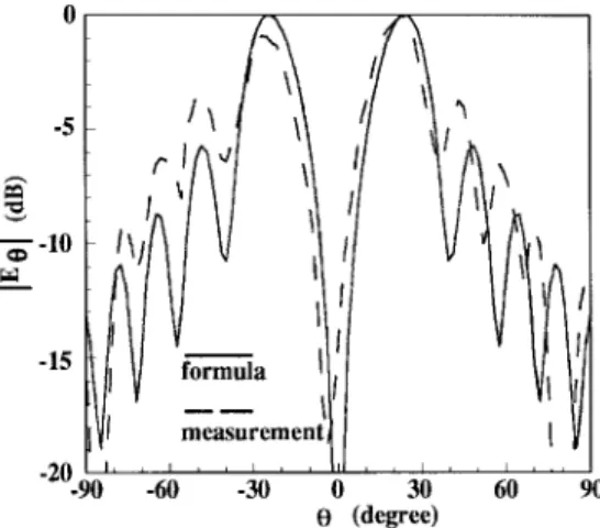
For clear exhibition of measured radiation pattern, the geometry and coordinates of the antenna is shown in Fig. 14. The -plane ( -plane in Fig. 15) radiation pattern is depicted by the dashed line in Fig. 15. The solid line in Fig. 15 represents the radiation pattern calculated by assuming the slotline as an ideal traveling-wave line source with amplitude
Fig. 15. TheE-plane radiation patterns obtained by our experiment and ideal line source formula. (f = 18 GHz, =k0= 0:9913; =k0= 00:0338).
Fig. 16. The mainbeam directions of the slotline leaky-wave antenna with different operational frequencies.
attenuation along the line included. The formula is as follows [23]:
(1) where is the length of the line source (the antenna). We can see that the calculated and measured patterns are similar to each other. Since, in practice, the slotline first higher order mode is more complicated than the simple line source assumed, we expect the minor deviations in the radiation patterns. As shown in Fig. 15, the radiation pattern of the slotline leaky-wave antenna is similar to that of the microstrip-line leaky-wave antenna [5]. Since there is no closed grounded plane, the slotline can radiate both above and below the sub-strate (and we have two mainbeams in this case). Additionally, the mainbeam directions of different operation frequencies are shown in Fig. 16. They also show reasonable agreement. The difference of the mainbeam directions (shown in Fig. 16) is due to the truncation of the substrate and alignment error in antenna measurement. The truncation results in the fact that the excited surface wave is reflected back to the inner region and the attenuation constant decreases. The smaller attenuation constant makes the mainbeam closer to the endfire direction.
The operational frequency of the leaky-wave line source is dominantly controlled by the width of the slot. In slotlines with finite-conductor planes, the attenuation constants of the first higher order mode are smaller in the radiation region due to less power being coupled to and surface waves of the background dielectric slab. The phase constants are smaller in the radiation region, which implies that the leaky-wave line source has a wider scanning range. The operational frequency of the leaky-wave line source is dominantly controlled by the width of the finite-conductor strips. Propagation characteristics of the surface-wave-like modes in slotlines are also presented. Examination of the current and field distributions suggests efficient excitation methods for the leaky-wave line sources based on the slotline. Two types of excitation are used to validate our numerical results and confirm the existence of the slotline first higher order mode. Experimental results show that the main beam direction coincides with that predicted by numerical data. To conclude, understanding of the propagation characteristics of the slotline first higher order mode is still not enough to use the slotline first higher order mode as an efficient leaky-wave line source. The investigations of the efficient feeding structures are also necessary, and these investigations are currently in progress. The results of which will be presented in the future.
REFERENCES
[1] R. C. Johnson, Antenna Engineering Handbook. New York: McGraw-Hill, 1993.
[2] F. Schwering and S. T. Peng, “Design of dielectric grating antennas for millimeter-wave applications,” IEEE Trans. Microwave Theory Tech., vol. MTT-31, pp. 199–209, Feb. 1983.
[3] R. E. Horn, H. Jacobs, K. L. Klohn, and E. Freibergs, “Single-frequency electronic-modulated analog line scanning using a dielectric antenna,”
IEEE Trans. Microwave Theory Tech., vol. MTT-30, pp. 816–820, May
1982.
[4] K. Solbach, “E-band leaky-wave antenna using dielectric image line with etched radiating elements,” in IEEE MTT-S Int. Microwave Symp.
Dig., Apr. 1979, pp. 214–216.
[5] W. Menzel, “A new traveling-wave antenna in microstrip,” Arch. Electr.
Uebertrag. Tech., vol. 33, pp. 137–140, Apr. 1979.
[6] A. A. Oliner and K. S. Lee, “The nature of the leakage from higher order modes on microstrip line,” in IEEE MTT-S Int. Microwave Symp.
Dig., Baltimore, MD, Jan. 2–4, 1986, pp. 57–60.
[7] A. A. Oliner, “Leakage from higher modes on microstrip line with application to antenna,” Radio Sci., vol. 22, no. 6, pp. 907–912, Nov. 1987.
[8] P. Lampariello and A. A. Oliner, “A novel phased array of printed-circuit leaky-wave line sources,” in Proc. 17th European Microwave
Conf., Rome, Italy, Sept. 1987, pp. 555–560.
[9] P. Lampariello, F. Frezza, H. Shigesawa, M. Tsuji, and A. A. Oliner, “Guidance and leakage properties of offset groove guide,” in IEEE
IEEE Trans. Microwave Theory Tech., vol. MTT-29, pp. 513–534, June
1981.
[15] J. S. Bagby, C. H. Lee, D. P. Nyquist, and Y. Yuan, “Identification of propagation regimes on integrated microstrip transmission lines,” IEEE
Trans. Microwave Theory Tech., vol. 41, pp. 1887–1894, Nov. 1993.
[16] S. T. Peng and A. A. Oliner, “Guidance and leaky properties of a class of open dielectric waveguide: Part I—Mathematical formulations,” IEEE
Trans. Microwave Theory Tech., vol. MTT-29, pp. 843–855, Sept. 1981.
[17] A. A. Oliner, S. T. Peng, T. I. Hsu, and A. Sanchez, “Guidance and leaky properties of a class of open dielectric waveguide: Part II—New physical effects,” IEEE Trans. Microwave Theory Tech., vol. MTT-29, pp. 855–869, Sept. 1981.
[18] Y. D. Lin, J. W. Sheen, and C. K. C. Tzuang, “Analysis and design of feeding structures for microstrip leaky wave antenna,” IEEE Trans.
Microwave Theory Tech., vol. 44, pp. 1540–1547, Sept. 1996.
[19] Y. D. Lin and J. W. Sheen, “Mode distinction and radiation efficiency analysis of planar leaky-wave line source,” IEEE Trans. Microwave
Theory Tech., vol. 45, pp. 1672–1680, Oct. 1997.
[20] J. W. Sheen and Y. D. Lin, “Surface-wave-like mode in slot line,” IEEE
Microwave Guided Wave Lett., vol. 6, pp. 259–261, July 1996.
[21] M. Tsuji, H. Shigesawa, and A. A. Oliner, “Simultaneous propagation of both bound and leaky dominant modes on conductor-backed coplanar strips,” in IEEE Int. Microwave Symp. Dig., Atlanta, GA, 1993, pp. 1295–1298.
[22] H. Shigesawa, M. Tsuji, and A. A. Oliner, “A new mode-coupling effect of coplanar waveguides of finite width,” in IEEE Int. Microwave Symp.
Dig., Dallas, TX, May 1990, pp. 1063–1066.
search Institute (ITRI), Hsinchu, Taiwan, R.O.C., as an RF Engineer and is currently developing a miniaturized RF filter and high-gain antenna. His research interests include the analysis and design of various planar-type leaky-wave antennas and the investigation of surface-leaky-wave leakage phenomena of uniplanar transmission lines.
Yu-De Lin (S’88–M’91) was born in Lotung, Tai-wan, R.O.C., on February 27, 1963. He received the B.S. degree in electrical engineering from National Taiwan University, Taipei, Taiwan, R.O.C., in 1985, and the M.S. and Ph.D. degrees in electrical engi-neering from the University of Texas at Austin, in 1987 and 1990, respectively.
In 1990, he joined the faculty of the Depart-ment of Communication Engineering, Institute of Communication Engineering, National Chiao Tung University, Hsinchu, Taiwan, R.O.C., where he is currently an Associate Professor. His current research interests include numer-ical methods in electromagnetics, characterization and design of microwave and millimeter-wave planar circuits, and analysis and design of microwave and millimeter-wave antennas.