DOI 10.1007/s11277-013-1357-8
A Multi-link Mechanism for Heterogeneous Radio
Networks
Shun-Neng Yang · Yung-Chun Lin · Chai-Hien Gan · Yi-Bing Lin· Chien-Ting Wu
Published online: 19 September 2013
© Springer Science+Business Media New York 2013
Abstract Nowadays, smart mobile devices drive the mobile traffic growth rapidly. Most
smart mobile devices are equipped with multiple radio network interfaces, such as High Speed Packet Access (HSPA), Long Term Evolution (LTE), and Wi-Fi. Therefore, integration of multiple networks is a viable solution to fulfill traffic offloading and the Quality-of-Service (QoS) requirement of data usage for mobile users. In this paper, we propose a multi-link mechanism to handle the radio network selection and switching between LTE and Wi-Fi networks. A Multi-Link Adaptor (MLA) and a Multi-Connection Manager (MCM) are proposed for the User Equipment (UE) and the core network, respectively, to handle the multi-link mechanism. The applications executed in the UEs do not need to be modified under the proposed approach. The MLA maintains a QoS class table and a routing table for the network selection procedure and uses the GPRS Tunneling Protocol-Control plane (GTP-C) control messages to execute network switching. In the future, we will measure the throughput of the multi-link network and the switch delay between the heterogeneous radio networks.
S.-N. Yang (
B
)· Y.-C. Lin · C.-H. GanInformation and Communications Research Laboratories, ITRI, Rm.505, Bldg.51, No.195, Sec.4, Chung Hsing Rd., Chutung, Hsinchu 31040, Taiwan, ROC e-mail: [email protected]
Y.-C. Lin
e-mail: [email protected] C.-H. Gan
e-mail: [email protected] S.-N. Yang· Y.-B. Lin · C.-T. Wu
Department of Computer Science, National Chiao Tung University, Hsinchu 30010, Taiwan, ROC
e-mail: [email protected] Y.-B. Lin
e-mail: [email protected] C.-T. Wu
Keywords Multi-link integrated networks· Radio network selection and switching · GTP tunnel· QoS class
1 Introduction
In the recent years, mobile devices (e.g., smartphones and tablets) drive mobile traffic growth rapidly. As forecasted by Cisco [1], Global mobile data traffic grew 70 % in 2012, and will grow at a Compound Annual Growth Rate (CAGR) of 66 % from 2012 to 2017. Overall mobile data traffic is expected to grow to 11.2 exabytes per month by 2017, a 13-fold increase over 2012. To deal with the traffic explosion, heterogeneous radio network integration is a cost-effective solution for mobile operators to reduce network congestion.
Currently, most smartphones or tablets are equipped with both cellular and Wi-Fi radio interfaces. Compared with the cellular technology, Wi-Fi utilizes non-licensed spectrum with a relatively low cost. It makes a viable solution by taking advantage of Wi-Fi technology for mobile operations to fulfill users’ data usage. Many mobile operators have deployed Wi-Fi hotspots integrated with mobile networks. In addition, several Wi-Fi offloading mechanisms were proposed to switch the cellular connections to the Wi-Fi connections. For example, Tai-wan’s Chunghwa Telecom has proposed an auto switch mechanism [2] to switch the network access from cellular to Wi-Fi for Apple iOS and Google Android platforms. However, this mechanism does not support seamless session mobility. Therefore, the application sessions are broken when the device switches the connection from Cellular to Wi-Fi.
The 3GPP and the IETF proposed two network protocols, GPRS Tunneling Protocol (GTP) [3,4] and Proxy Mobile IP (PMIP) [5] to support IP mobility. Both GTP and PMIP based approaches rely on an all-IP core network to enable session mobility. One of the PMIP solutions was presented in [6], but it lacked the services classification method and the network selection mechanism. In [7], the heterogeneous network interworking issues (e.g., bandwidth aggregation) of the application, transport, network, and link layers had been surveyed. In this paper, we propose a GTP-based approach for cellular (i.e., LTE) and Wi-Fi interworking. In our approach, User Equipment (UE) is required to install a Multi-Link Adaptor (MLA) to manage both the LTE and Wi-Fi network interfaces. The MLA provides a unified radio network interface to host applications, such that the application connections are not affected when the radio link is switched (e.g., from LTE to Wi-Fi). In addition, this paper proposes a network selection mechanism for MLA to select a suitable radio network interface based on the characteristics of an application. The network selection mechanism first collects some transmission packets of an application, analyzes the traffic pattern for the application, and finally selects an appropriate radio interface for the application. Multiple connections of a UE are allowed to deliver through different radio networks concurrently. A Multi-Connection Manager (MCM) is deployed in the mobile core network to coordinate the multi-link connections. In our approach, the applications need not to be modified.
The paper is organized as follows. Section2describes the network architecture and the GTP Protocol. Section3introduces the software architectures of Multi-Link Adaptor and Multi-Connection Manager. Section4proposes the network selection procedure. Section5 presents the network switching procedure. Conclusions are given in Sect.6.
2 Network Architecture, GPRS Tunneling Protocol, and QoS Classes
This section first discusses the Wi-Fi and LTE integrated network architecture. Then we introduce the GPRS Tunneling Protocol used in the integrated network. Finally we describe
C
A B
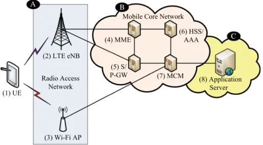
Fig. 1 Wi-Fi and LTE integrated network architecture
the Quality-of-Service (QoS) classes of the applications that will be used in the network selection scheme to switch the GTP tunnels.
2.1 Wi-Fi and LTE Integrated Network Architecture
Figure1depicts the integrated network architecture for multiple radio access networks (e.g., the Wi-Fi and LTE in this example) through the Multi-Connection Manager [MCM; see Fig.1(7)] and Multi-Link Adaptor [MLA in UE; see Fig.1(1)]. The UE equipped with MLA has both LTE and Wi-Fi network access interfaces. The UE connects to the mobile core network [see Fig.1(B)] through either LTE base stations [eNBs; see Fig. 1(2)] or Wi-Fi Access Points [APs; see Fig.1(3)] in the radio access network [see Fig.1(A)]. The MLA in the UE helps to schedule, reschedule, and balance the packet flows of the UE.
To accommodate the Wi-Fi traffic, the MCM is introduced to the LTE core network that consists of the Mobility Management Entity [MME, see Fig.1(4)], Serving Gateway/Packet data network Gateway [S/P-GW, see Fig.1(5)], Home Subscriber Server/Authentication, Authorization, and Accounting server [HSS/AAA, see Fig.1(6)].
The MME hosts the UE mobility related functions, such as authentication, location track-ing and management, connection management, and interworktrack-ing with the S/P-GW and the HSS/AAA [8]. The S-GW is responsible for data delivery between the LTE core network and the radio access network. The P-GW is responsible for managing connectivity between the LTE core network and the external data network [see Fig.1(C)]; specifically, it provides the connection between the UE and an application server [see Fig.1(8)].
The HSS is a database for storing information related to the users. It also supports the user authentication and the network access authorization [9]. The 3GPP AAA server authenticates Wi-Fi users based on Universal Subscriber Identity Module (USIM) credentials, and inter-acts with the HSS to retrieve the non-3GPP access authorization information for the 3GPP subscribers [10,11].
The MCM interworks with the MLA in the UE to manage the multiple radio access links for the UE. To manage these links, the MCM exchanges the control messages with the MLA
to maintain data transmission tunnels between the MCM and the MLA. Based on the request of the MLA, the MCM transmits data through different radio connections. In our multi-link approach, the GPRS Tunneling Protocol is used to control the LTE and Wi-Fi link switch and transport the data packets between the UE and the MCM server.
2.2 GPRS Tunneling Protocol
GPRS Tunneling Protocol is an IP-based communications protocol that maintains GTP tun-nels to carry user data in the GPRS, the UMTS or the LTE core networks. The GTP protocol is first proposed for GPRS to tunnel user plane packets between GPRS Support Nodes (GSNs) in the GPRS backbone network, and it is therefore called the GPRS tunneling protocol.
GTP is composed of the GPRS Tunneling Protocol-Control plane (GTP-C) protocol [3] and the GPRS Tunneling Protocol-User plane (GTP-U) protocol [4]. A GTP-C flow is log-ically associated with one or more GTP-U tunnels, while the GTP-U protocol realizes the GTP tunnels that carry the encapsulated user plane data between the tunnel endpoints (e.g., P-GW or MCM in Fig.1). A GTP tunnel is a one-direction tunnel. Multiple GTP tunnels can be established between each set of endpoints. At each tunneling node, a GTP tunnel is identified by a Tunnel Endpoint Identifier (TEID), an Internet Protocol (IP) address, and a User Datagram Protocol (UDP) port number. The TEID is a locally unique number assigned by the receiving endpoint of a GTP tunnel. The identity is present in the GTP header to indicate which tunnel a particular user data packet belongs to.
Our approach extends the GTP protocols to implement data bearers between the UE and the MCM. The GTP-C is used for maintaining the tunnels between the UE and the MCM, while the GTP-U is used for carrying user data between the UE and the MCM through the GTP tunnels. The GTP-U packet consists of a GTP-U header and a GTP-U payload. The GTP-U header is composed of a source UDP port, a source IP [i.e., IP of the network interface of UE (MCM)] and a destination IP [e.g., IP of the corresponding network interface of MCM (UE)]. The GTP-U payload is the carried user data packet.
With the LTE and the Wi-Fi technologies, our approach manages multiple radio access links between the UE and the MCM by different GTP tunnel sets. Our mechanism allows the MLA to activate a multi-link session, to deactivate the multi-link session, to adjust, update, and switch the access link of a session. The MLA uses the following GTP-C control messages to manipulate the multi-link session.
• Create Session Request/Response: this message pair establishes the tunnels as the first bearer to carry the user plane data between the UE and the MCM.
• Modify Bearer Request/Response: this message pair modifies the parameter settings for a user plane bearer between the UE and the MCM.
• Delete Session Request/Response: this message pair removes the existed user plane bearer between the UE and the MCM.
The MLA uses a network selection scheme (to be elaborates in Sect.4) that switches the GTP tunnels based on the QoS requirements of the applications. The QoS class is described in the next subsection.
2.3 Quality-of-Service Classes
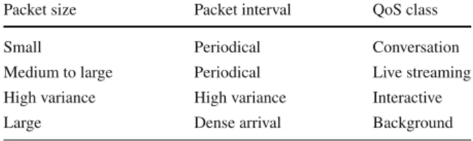
Following the Universal Mobile Telecommunications System (UMTS) specification [12], we classify the applications into four Quality-of-Service classes:
Table 1 The characteristics of
the QoS classes Packet size Packet interval QoS class
Small Periodical Conversation
Medium to large Periodical Live streaming High variance High variance Interactive
Large Dense arrival Background
• Conversation: the traffic of conversational service typically carries small-sized packets (e.g., 40–500 bytes), where the transmission data are compressed. The application infor-mation is sampled by a fixed rate, and the packets are periodically transmitted by a fixed period (e.g., 15–40 ms). A representative service is Voice over Internet Protocol (VoIP). • Live Streaming: the live streaming service typically carries medium to large-sized packets (e.g., 500–1,600 bytes), where the application packets are transmitted periodically by a fixed period (e.g., 15–100 ms). A representative service is video streaming.
• Interactive: the traffic pattern of interactive service depends on the relationship of the request and response messages. The variance of packet sizes and transmission intervals are high (e.g., the packet size may range from 40 to 1,600 bytes). A representative service is web browsing.
• Background: the traffic typically carries large-sized packets (e.g., 1,000–1,600bytes), where the size of the source data is fixed, and the applications do their best to fill up the packets. The packet transmission interval is short (e.g., 0.02–0.08 ms) to finish transmis-sion as early as possible. A representative service is File Transfer Protocol (FTP). The characteristics of each QoS class are summarized in Table1.
3 Multi-link Adaptor and Multi-connection Manager
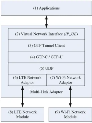
This section describes the software architectures of the Multi-Link Adaptor (MLA) and the Multi-Connection Manager (MCM). Figure2shows the MLA software architecture, which is a client-side software module installed at the multi-network-module UE (e.g., the UE equipped with both LTE and Wi-Fi network modules). The MLA consists of the virtual network interface [see Fig.2(2)], and the GTP tunnel client [see Fig.2(3)]. The virtual network interface provides a unified network interface for applications [see Fig.2(1)], where an IP address is allocated to the virtual network interface as the IP_UE. All applications in the UE use the IP_UE to access Internet services, and the IP_UE will not be changed when the physical network link (i.e., LTE or Wi-Fi link) is switched.
The GTP tunnel client is responsible for the creation, modification, deletion of the GTP tunnel (i.e., maintenance of the GTP tunnel) between the MLA and the MCM by exchanging the GTP-C messages [see Fig.2(4)]. It also handles data packet routing between the virtual network interface and physical network interfaces (e.g., LTE or Wi-Fi) by using the GTP-U protocol.
Initially, a default radio network is selected by the GTP tunnel client. When the virtual net-work interface receives IP packets from an application, it first sends to the GTP tunnel client. The GTP tunnel client encapsulates the received packet into GTP-U packet [see Fig.2(4)]. The GTP-U packet is implemented by the UDP protocol [see Fig.2(5)] and is sent by the network adaptor [e.g., LTE or Wi-Fi, see Fig.2(6), (7)] to the corresponding network module [Fig.2(8), (9)). We note that the sending network could be modified by the GTP tunnel client
Fig. 2 MLA software architecture
(2) Virtual Network Interface (IP_UE) (3) GTP Tunnel Client Multi-Link Adaptor (1) Applications (8) LTE Network Module (9) Wi-Fi Network Module (4) GTP-C / GTP-U (5) UDP (6) LTE Network Adaptor (7) Wi-Fi Network Adaptor
when it finds that the other network is more suitable for the application than the default one (the details are described in the next section).
In addition, if the GTP tunnel client receives a GTP-U packet from the network module, it first removes the GTP-U header and sends the user data packet (i.e., the payload of the GTP-U packet) to the virtual network interface. Then the virtual network interface routes the user data packet to the application.
Figure3shows the MCM software architecture, which consists of the IP management [see Fig.3(1)] and the GTP tunnel server [see Fig.3(2)]. The IP management module is responsible for IP address allocation to the virtual network interface of the MLA for a UE. The IP address is allocated by the Dynamic Host Configuration Protocol (DHCP) function.
The GTP tunnel server is responsible for GTP tunnel management for a UE. It stores the IP addresses of the interfaces of UE and the current UE-established GTP tunnel ID (i.e., TEID) to identify the UE. It also interworks with the GTP tunnel client of the MLA to maintain the GTP connections through the GTP-C [see Fig.3(3)] messages for network switching.
When the GTP tunnel server receives a packet from the external networks [Fig.3(9)], the GTP tunnel server checks the destination IP of the packet and finds the corresponding TEID. Then it uses the GTP-U [see Fig.3(3)] to forward the packet to the destination UE. The GTP-U packet is sent by UDP [see Fig.3(4)] and IP [IP of intranet; see Fig.3(5)] through the internal network interface [see Fig.3(8)].
When the GTP tunnel server receives data from a UE through internal network interface, the GTP tunnel server checks the destination IP of the data and finds the corresponding routing path. Then the GTP tunnel server removes the GTP-U header and sends the IP packet (which includes the TCP/UDP and IP headers; see Fig.3(6), (7)] through the external network interface [see Fig.3(9)] to the corresponding destination Internet server.
Fig. 3 MCM software architecture (1) IP Management (2) GTP Tunnel Server Multi-Connection Manager (8) Internal Network Interface (9) External Network Interface (3) GTP-C / GTP-U (4) UDP (5) IP (Intranet) (7) IP (Internet) (6) TCP/UDP
Table 2 The characteristics and the QoS requirements of the QoS classes
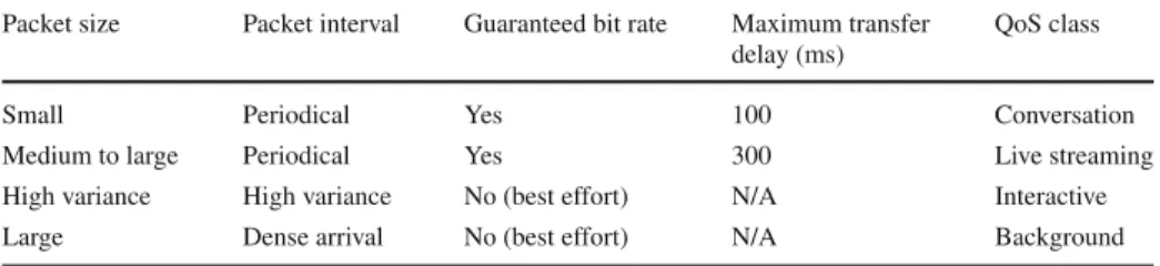
Packet size Packet interval Guaranteed bit rate Maximum transfer delay (ms)
QoS class
Small Periodical Yes 100 Conversation
Medium to large Periodical Yes 300 Live streaming
High variance High variance No (best effort) N/A Interactive
Large Dense arrival No (best effort) N/A Background
4 The Network Selection Procedure
To exercise the network selection procedure, the MLA (i.e., the GTP tunnel client of MLA) maintains two tables: the QoS class table and the routing table, where the details of QoS class table are described in Sect.2. Since the QoS class table follows the UMTS specification [12], each class can map to corresponding QoS requirements of the UMTS specification [13]. The QoS requirements include the support of Guaranteed Bit Rate (GBR, e.g, guarantee 500 Kbps) and the maximum transfer delay (e.g., 100 ms from the MLA to the MCM). Table2 extends Table1with the QoS requirements for each QoS class.
The routing table is utilized for packet routing. This table contains two entries, which are serving port number (port number of the virtual network interface of MLA for an application) and the serving network module (network module for transmitting the application packets). In general, a service flow utilizes only one serving port. Thus we use the serving port to uniquely identify a service flow. Table3indicates an example of the routing table.
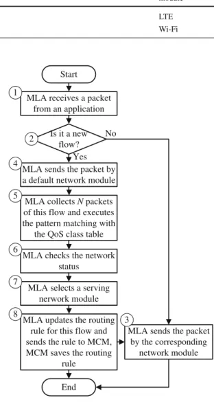
Figure4illustrates the network selection procedure, the execution steps are described as follows.
Step 1. An application (e.g., FTP) initiates a new service flow, and the virtual network
Table 3 An example of the
routing table Serving port number Serving networkmodule
1234 LTE
5678 Wi-Fi
Fig. 4 The network selection procedure
MLA receives a packet from an application
MLA sends the packet by a default network module
Start
MLA collects N packets of this flow and executes the pattern matching with
the QoS class table MLA checks the network
status
MLA updates the routing rule for this flow and sends the rule to MCM, MCM saves the routing
rule End 1 4 5 6 8 Is it a new flow?
MLA sends the packet by the corresponding network module Yes No 3 2
MLA selects a serving nerwork module 7
Step 2. The GTP tunnel client of MLA checks the routing table with the source port (i.e.,
the serving port) of the packet header to see if the routing rule of the source port exists in the table. If so, the MLA executes Step 3, otherwise goes to Step 4.
Step 3. The MLA retrieves the serving network module from the routing table and delivers
the packet by the corresponding network module. The procedure exits.
Step 4. The MLA sends the packet through a default network module (e.g., LTE). The
MLA then creates a temporary routing rule in the routing table with the serving port and the default serving network module for handling the packets of this service flow.
Step 5. The MLA collects N packets of this service flow and compares the size of the
collected packets with the packet size range of each QoS class (except for the interactive service). If most collected packets (e.g., more than 90 %) match one or more QoS classes, the MLA then compares the interval of the collected packets with the packet interval range
of each QoS class. The traffic pattern of the collected packets should at most match one QoS class (i.e., conversation, live streaming, or background). If none of the above classes is matched, the service flow is identified as an interactive class service.
Step 6. The MLA checks the network status (e.g., the GBR or the available network
bandwidth and the transfer delay) to select a serving network module. The required bit rate of the services which belongs to the first two QoS classes could be estimated by counting the total packet sizes of data in a period of time. The LTE network guarantees the bit rate by the establishment of dedicated bearer [14]. As for the available network bandwidth, we assume that the MCM monitors the available bandwidths of LTE eNBs and Wi-Fi APs (e.g., by the performance management protocols defined in [15,16]). Then the MLA sends a query to the MCM for retrieving the available bandwidth information of the networks that the UE currently uses. The transfer delay between the MLA and the MCM is measured by the ping command of the Internet Control Message Protocol (ICMP) [17].
Step 7. After retrieving the status of the networks, the MLA selects a suitable radio
network interface according to the QoS requirements of the QoS class that fits the service flow. The MLA sequentially checks the QoS requirements (i.e., GBR or available network bandwidth and transfer delay) to see if each network matches the requirements of the QoS class. If more than one or none of the networks matches the requirements, the MLA selects the network having the better performance (e.g., higher available network bandwidth or lower transfer delay).
Step 8. The MLA updates the routing rule according to the network selection result in Step 7 to replace the old one created in Step 4. Then the MLA sends the updated routing
rule to the MCM (i.e., the GTP tunnel server), and the MCM saves this routing rule in the table, and then executes Step 3.
In the routing table, every rule is associated with an expiration timer Tewhen it is created in
Step 4 of Fig.4. When Teis expired, the flow is considered inactive, and the GTP client/server will remove the corresponding rule from the routing table.
5 The Network Switching Procedure
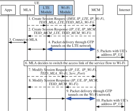
This section describes the GTP tunnel creation and the network switching procedures between the MLA and the MCM. Figure5shows the message flow with the following steps.
Step 1. Initially the GTP Tunnel Client of the MLA sends a GTP Create Session Request
message to the MCM to create the multi-link tunnel for the UE after the UE attachment. This message carries the UE’s identity (e.g., International Mobile Subscriber Identity, or IMSI in this example), the UE’s LTE and Wi-Fi addresses (i.e., the IP_LTE and the
IP_Wi-Fi) as tunneling transport addresses, and the MLA’s receiving TEIDs of the LTE
and the Wi-Fi networks (i.e., the TEID_MLA_LTE and the TEID_MLA_Wi-Fi). After this message is received by the MCM, the new downlink tunnels are established from the MCM to the MLA through the LTE and the Wi-Fi networks, and the UE can receive the downlink packets from the MLA through both the LTE and Wi-Fi networks. The default downlink radio tunnel is set to LTE.
Step 2. The MCM assigns an IP address for the UE (i.e., the IP_UE) by the IP management
module. Then the MCM responses with the Create Session Response message to the MLA with the parameters IP_UE, the MCM tunneling address (i.e., the IP_MCM), and the receiving TEIDs in the MCM (i.e., the TEID_MCM_LTE and the
TEID_MCM_Wi-UE
Apps MLA LTE
Module
Wi-Fi
Module MCM Internet
6. MLA decides to switch the access link of the service flow to Wi-Fi 3. Connect to MLA
1. Create Session Request (IMSI, IP_LTE, IP_Wi-Fi,
TEID_MLA_LTE, TEID_MLA_Wi-Fi)
2. Create Session Response (IP_UE, IP_MCM,
TEID_MCM_LTE, TEID_MCM_Wi-Fi)
7. Modify Session Request (IP_UE, IP_Wi-Fi,
TEID_MLA_Wi-Fi, Serv_Port)
8. Modify Session Response (IP_UE, IP_MCM,
TEID_MCM_Wi-Fi)
5. Packets with UE’s address IP_UE
10. Packets with UE’s address IP_UE 4. Packet delivery through GTP
tunnels on the LTE network
9. Packet delivery through GTP tunnels on the Wi-Fi network
Fig. 5 Message flow for network switching procedure
Fi). After receiving this message, the uplink tunnels are established from the MLA to the
MCM through both the LTE and the Wi-Fi networks. The default uplink radio tunnel is set to LTE.
Step 3. The UE application connects to the MLA for packet delivery.
Step 4. All user packets are transmitted between the UE and the MCM through the MLA
and the LTE network. The MLA encapsulated the packets and sent them to the MCM through the GTP tunnel with the uplink TEID (e.g., the LTE TEID TEID_MCM_LTE). The packets are delivered and received through the GTP tunnels on the LTE network between the MLA and the MCM.
Step 5. The MCM acts as the tunnel endpoint by processing the user plane data based
on the packet directions. For an uplink packet from the UE, the MCM decapsulates the tunneled packet (e.g., with the uplink LTE TEID TEID_MCM_LTE) and forwards it to the Internet with the IP_UE as the source packet address. For a downlink packet to the UE (destined for the IP_UE address), the MCM checks its destination port in the routing table and the MCM encapsulated the packet and sent it to the UE through the GTP tunnel with the downlink TEID (e.g., the LTE TEID TEID_MLA_LTE).
Step 6. Through the traffic pattern analysis in Fig.4, the GTP tunnel client of the MLA decides to switch the access link of the service flow from LTE to Wi-Fi.
Step 7. The GTP tunnel client of the MLA sends a GTP Modify Session Request message
to the MCM through the UE’s Wi-Fi module with the IP_UE as the UE’s identity, the
and the serving port number (i.e., Serv_Port) of the flow. After this message is received by the MCM, the MCM creates the corresponding routing rule for this flow (see Step 8 of the network selection procedure), and the downlink packets of the flow are transmitted from the MCM to the MLA through the Wi-Fi network.
Step 8. The MCM responses with the Modify Session Response message to the MLA
with the parameters IP_UE, the IP_MCM and the receiving TEID in the MCM (i.e.,
TEID_MCM_Wi-Fi). After receiving this message, the uplink packets of the flow are
transmitted from the MLA to the MCM through the Wi-Fi network.
Step 9. The service flow of the UE application then accesses the Internet through the
MLA and the Wi-Fi network module. The packets are delivered and received through the GTP tunnels on the Wi-Fi network between the MLA and the MCM.
Step 10. The MCM decapsulates the uplink tunneled packet from the UE (with the uplink
Wi-Fi TEID TEID_MCM_Wi-Fi) and forwards it to the Internet. For a downlink packet to the UE (destined for the IP_UE address), the MCM encapsulated the packet and sent it to the UE through the GTP tunnel with the downlink Wi-Fi TEID (i.e., TEID_MLA_Wi-Fi). The above example illustrates how our approach switches the radio link of a service flow for the user application. In this example, we use GTP tunnels as the data bearer to carry the user packets transmitted either through the LTE network or the Wi-Fi network. Our approach adapts the modified GTP-C protocols for session management, and the maintenance between the MCM and the MLA is also based on the GTP-C protocol, which is utilized by the LTE core network to carry the user data between the S-GW and P-GW. Our multi-link switching approach is similar to the handover procedure with S-GW relocation in LTE. In this case, the MCM acts as a P-GW to switch the data path between LTE and Wi-Fi without establishing extra tunneling between the MCM and the MLA, and thus mitigates the tunneling overhead.
6 Concluding Remarks
This paper presented a multi-link mechanism to deal with selection and switching between LTE and Wi-Fi networks. The Multi-Link Adaptor (MLA) and the Multi-Connection Manager (MCM) are proposed respectively for the UE and the core network to handle the multi-link mechanism. The applications executed in the UE do not need to be modified under the pro-posed approach. The MLA maintains the QoS class table and the routing table for the network selection procedure and uses the GTP-C control messages to execute the network switching procedure. In the future, we will measure the throughput of the multi-link network and the switch delay between the heterogeneous radio networks for evaluating the performance of the multi-link mechanism.
Acknowledgments This paper was supported in part by NSC 101-2221-E-009-032, Academia Sinica AS-102-TP-A06, Chunghwa Telecom, Nokia Siemens Networks, ITRI/NCTU JRC Research Project, the ICL/ITRI Project, Department of Industrial Technology (DoIT) Academic Technology Development Program 101-EC-17-A-03-S1-193, the MoE ATU plan, and the Technology Development Program of the Ministry of Economic Affairs (MoEA TDP), Taiwan.
References
1. Cisco Corporation. (2012). Cisco visual networking index: Global mobile data traffic forecast update
2. Yu, C., Hwang, A. (2013). Taiwan market: Chunghwa telecom begins EAP-SIM off-loading of 3G traffic
onto Wi-Fi. News. DIGITIMES.http://www.digitimes.com/pda/a20130115PD201.html. Accessed April 25, 2013
3. 3GPP. (2013). Evolved general packet radio service (GPRS) tunnelling protocol for control plane
(GTPv2-C), Stage 3. 3GPP TS 29.274 (Version 12.0.0).
4. 3GPP. (2013). General packet radio system (GPRS) tunnelling protocol user plane (GTPv1-U). 3GPP TS 29.281 (Version 11.6.0).
5. Gundavelli, S., Leung, K., Devarapalli, V., Chowdhury, K., Patil, B. (2008). Proxy mobile IPv6. IETF RFC 5213.
6. Trung, T. M., Han, Y.-H., Choi, H.-Y., Geun, H. Y. (2011). A design of network-based flow mobility based on proxy mobile IPv6. In IEEE conference on, computer communications workshops (INFOCOM
WKSHPS).
7. Ramaboli, A. L., Falowo, O. E., & Chan, A. H. (2012). Bandwidth aggregation in heterogeneous wireless networks: A survey of current approaches and issues. Journal of Network and Computer Applications,
35(6), 1674–1690.
8. 3GPP. (2013). Evolved universal terrestrial radio access (E-UTRA) and evolved universal terrestrial
radio access network (E-UTRAN), Overall description, Stage 2. 3GPP TS 36.300 (Version 11.5.0).
9. Firmin, F. (2012). The evolved packet core. 3GPP MCC.http://www.3g.pp.org/The-Evolved-Packet-Core. Accessed April 30, 2013
10. 3GPP. (2013). Architecture enhancements for non-3GPP accesses. 3GPP TS 23.402 (Version 12.0.0). 11. 3GPP. (2012). 3GPP system to wireless local area network (WLAN) interworking, WLAN user equipment
(WLAN UE) to network protocols, Stage 3. 3GPP TS 24.234 (Version 11.3.0).
12. Lin, Y.-B., & Pang, A.-C. (2005). Wireless and mobile All-IP networks. Hoboken, NJ: Wiley. 13. 3GPP. (2012). Quality of service (QoS) concept and architecture. 3GPP TS 23.107 (Version 11.0.0). 14. 3GPP. (2013). Non-access-stratum (NAS) protocol for evolved packet system (EPS), Stage 3. 3GPP TS
24.301 (Version 12.0.0).
15. 3GPP. (2012). Telecommunication management, performance management (PM), performance
measure-ments evolved universal terrestrial radio access network (E-UTRAN). 3GPP TS 32.425 (Version 11.4.0).
16. 3GPP. (2012). Telecommunication management, self-organizing networks (SON), concepts and
require-ments. 3GPP TS 32.500 (Version 11.1.0).
17. Postel, J. (1981). Internet control message protocol. IETF RFC 792. Author Biographies
Shun-Neng Yang received the B.S. and the M.S. degrees in Computer Science and Information Engineering from National Cheng Kung Uni-versity (NCKU), Tainan, Taiwan, R.O.C., in 2004 and 2006, respec-tively. He is currently working toward the Ph.D. degree at NCTU. He is also a Researcher in the Information and Communications Research Labs, Industrial Technology Research Institute (ICL/ITRI). His cur-rent research interests include smart grid network, wireless and mobile computing, personal communications services, and performance mod-eling.
Yung-Chun Lin received the B.S. and M.S. degrees in Computer Sci-ence and Information Engineering from National Chiao Tung Univer-sity (NCTU), Taiwan, in 2001, 2003, respectively. He is currently pur-suing the Ph.D. degree in Computer Science. He has been a Researcher in the Information and Communications Research Labs, Industrial Technology Research Institute (ICL/ITRI), Taiwan. His research inter-ests include design and analysis of a personal communications services network, the cellular protocols (UMTS/GPRS/GSM), and mobile com-puting.
Chai-Hien Gan (M’05) received his B.S degree in computer sci-ence from Tamkang University in 1994, Taipei County, Taiwan, and both his M.S. and Ph.D. degrees in computer science and informa-tion engineering from Nainforma-tional Taiwan University, Taipei, Taiwan, in 1996 and 2005, respectively. From March 2005 to July 2007, he was a Research Assistant Professor in Department of Computer Science, National Chiao Tung University, Taiwan. Since July 2007, he has been a Researcher in the Information and Communications Research Labs, Industrial Technology Research Institute (ICL/ITRI), Taiwan. His cur-rent research interests include wireless and mobile computing, personal communications services, IP multimedia subsystem, and wireless Inter-net.
Yi-Bing Lin is Senior Vice President and Lifetime Chair professor of National Chiao Tung University (NCTU). He is also an Adjunct Research Fellow, Institute of Information Science, Academia Sinica, Research Center for Information Technology Innovation, Academia Sinica, and a member of board of directors, Chunghwa Telecom. He serves on the editorial boards of IEEE Trans. on Vehicular Technology. He is General or Program Chair for prestigious conferences including ACM MobiCom 2002. He is Guest Editor for several journals includ-ing IEEE Transactions on Computers. Lin is the author of the books Wireless and Mobile Network Architecture (Wiley, 2001), Wireless and Mobile All-IP Networks (John Wiley, 2005), and Charging for Mobile All-IP Telecommunications (Wiley, 2008). Lin received numer-ous research awards including 2005 NSC Distinguished Researcher, 2006 Academic Award of Ministry of Education and 2008 Award for Outstanding contributions in Science and Technology, Executive Yuen, 2011 National Chair Award, and TWAS Prize in Engineering Sciences, 2011 (The Academy of Sciences for the Developing World). He is in the advisory boards or the review boards of various government orga-nizations including Ministry of Economic Affairs, Ministry of Education, Ministry of Transportation and Communications, and National Science Council. Lin is AAAS Fellow, ACM Fellow, IEEE Fellow, and IET Fellow.
Chien-Ting Wu received the B.S.C.S. degree from National Chiao Tung University (NCTU), Hsinchu, Taiwan, R.O.C., in 2009. She is currently working toward the M.S.C.S. degree at NCTU. Her cur-rent research interests include multiple wireless networks and network-based mobility management.