Yajun Li Vol. 2, No. 10/October 1985/J. Opt. Soc. Am. A 1677
Phase distribution near the focus in systems of different
Fresnel numbers
Yajun Li*Institute of Electro-Optical Engineering, National Chiao Tung University, 1001 Ta Hsueh Road, Hsinchu, Taiwan 300, China
Received January 31, 1985; accepted June 3, 1985
Three-dimensional phase distribution near the focal plane is demonstrated by cross-section profiles of cophasal surfaces. The phase distribution in the focal plane and the phase anomaly in the focus are discussed in greater de-tail. Numerical results obtained are arranged systematically with Fresnel numbers sampled between 0.5 and 100, a sampling that covers conventional and unconventional cases.
1. INTRODUCTION
Phase distribution near the focus when a converging,
mono-chromatic, spherical wave is diffracted at a circular aperture
on an opaque screen has been treated by many authors after Gouy's discovery in 1890 of the so-called phase anomaly nearthe focus.1- The extensive literature related to this subject
is cited in Ref. 3.Attention is now paid to the same problem, because in a
number of publications
5-'
2authors have revealed that, in
principle, many of the classical results are merely special in-stances that are covered by more-general laws. For instance,classical authors
3predicted that the cophasal surfaces in the
immediate neighborhood of the focus are nearly plane, while
Gouy' argued that a spherical converging light wave passing
through its focus undergoes a rapid phase change of ir rad. In this paper, it is shown that the cophasal surfaces near the focusare approximately spherical, that the rapidity of the phase
change along a selected geometrical ray through the focus isdirectly proportional to the Fresnel number of the diffracting
aperture, and that therefore Gouy's predictions of phase
anomaly near the focus may describe phenomena in focusingsystems only when their Fresnel numbers are considerably
larger than unity. Moreover, phase distribution in the focal
plane needs to be discussed, because in the focal plane an additional parabolic phase factor has to be taken into accountif some of the assumptions underlying the classical
investi-gations are modified.7The numerical results obtained in this paper are displayed
systematically by curves and cross-section profiles with the
Fresnel number sampled between 0.5 and 100.
2. EXPRESSIONS OF PHASE DISTRIBUTION
IN THE FOCAL REGION
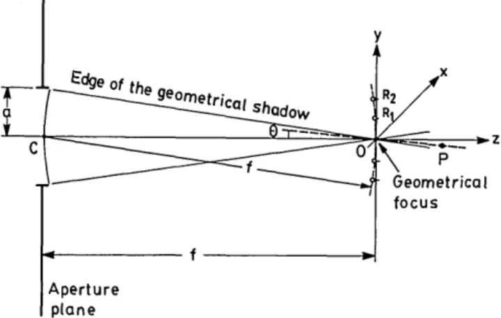
When a uniform converging spherical wave working at a cir-cular frequency c emerges from a circir-cular aperture in an opaque screen, it is seen that it travels along the z axis toward the geometrical focus at x = y = z = 0 (Fig. 1). By using the
scalar theory of diffraction, it can be predicted that the
be-havior of the diffracted field is determined by the followingparameters: A, amplitude; a, aperture radius; X, wavelength;
and f, focal length. The last three parameters can be
com-bined into the Fresnel number N
= a2/Xfand the f number
F = f/2a.
In the present investigation, attention is centered on the
phase behavior of the diffraction field near the focus, which
is, apart from a periodic factor exp(-iwt), given by6'7'1 1'1 2ON(UN, VN) =
1
uN/2rN
[4F2 UN + VN]-
a(UN,
VN)
-2
'
(mod 2ir). (2.1)This is the central equation of this paper. In this equation
UN
= 2rN
zif1 + zf/
VN =2irN
rna1 +
zif
Er = (x 2+ y2 )1/2], (2.2a) (2.2b)and
S sna=(C2 + S2)1/2' CCOS
a =(C
2+ S2)1/2
(2.3)with
C -iS = 2 1JO(VNp) exp - UNP2)PdP. (2.4)
The notation (mod 27r) in Eq. (2.1) means that
ONis
inde-terminate according to the extension of an additive multiple
of 2zr.The multivalued function
ON has a branch point at eachzero of the intensity.
3At all points other than the points of
zero intensity, ON is continuous with respect to (UN,
VN).
In
the special case
of (UN = 0, VN =0), i.e., at the geometrical
focus (which is not a branch point), we obtain from Eq. (2.1)
that
N(ON
0) = -2+ mMr,
2We can then define
(m = 0,1, 2,...). (2.5a)
ON(°, ) =
-as the principal value of ON(O,0)-(2.5b)
By substituting these equations into Eqs. (2.3), we obtain
Aperture
plane
Fig. 1. Illustration of the notation.
3. PHASE DISTRIBUTION IN THE FOCAL
PLANE
By putting UN = 0 into Eq. (2.1), the following result is
ob-tained:
ON(O, V) = - V2 - a(0,U) -2'
4r1N 2 (mod 2wr). (3.1)
In this equation the dimensionless parameter
UN,as defined
by Eq. (2.2b), has been replaced by
r
v = 27rN - . (3.2)
a
Under the condition
UN =0, Eq. (2.4) yields the following
results:
C = Besinc(M) = 2J
1(v)/v
and S = 0. (3.3)sin a = 0
and
cos a = Besinc(u)ABesinc(v)j. (3.4)From these results, it is clear that the principal value of a(0,
U) in Eq. (3.1) is either 0 or 7r, according to whether the specialwZ function Besinc(v) > 0 or Besinc(v) < 0. These inequalities
are equivalent, respectively, to
fosr<R,
R2p<r<R2p+l,
and
(p = 1,2,3,...).
(3.5b)Here Rp is the radius of the pth dark ring in the Airy pattern
where the available regions of the following formulas are
di-vided:'kN(O,
U) = - U2- -r47rN 2
when inequalities (3.5a) hold, and
kN(O, V) = 1 V2 + r
4rN 2
(mod 27r) (3.6a)
(mod 2r)
(3.6b)
when inequalities (3.5b) hold.
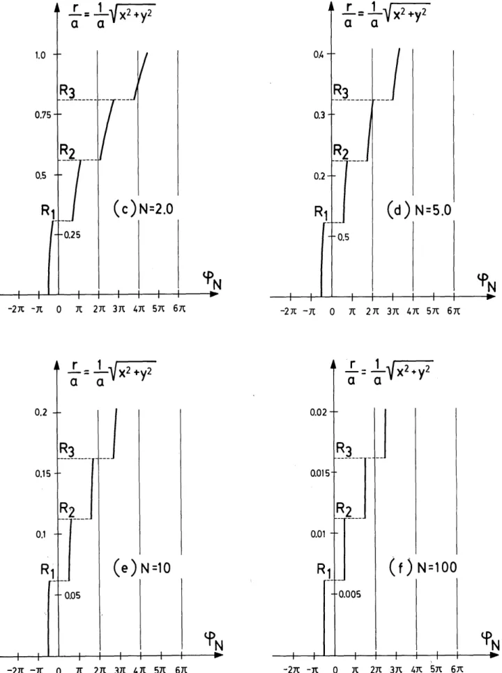
Phase distributions in the focal plane are shown by the
parabolic curves in Figs. 2(a), 2(b), 2(c), 2(d), 2(e), and 2(f) for systems of Fresnel number N = 0.5, 1, 2, 5, 10, 100,respec-tively. These parabolic curves are cut into segments by the
points of zero intensity at r = Rp, at which the phase
distri-bution undergoes rapid transitions of 7r
rad. In addition, since
calculations in the present study are limited to a region smallerthan the fourth dark ring of the Airy pattern, the v values in
(a) N=O.5
(b) N-1.O
-
i
0
xt2nt 3it
4x 5Yi 6Jt 7t Bit 9iI focus (3-5a)
R2pj < r <
R2p,r=
_1VX2*y2
a
a
a
r
= _1VX2+y2
a
ji
0
ir
27r
37t 4n 57t 6R 77t 87E 9nVol. 2, No. 10/October 1985/J. Opt. Soc. Am. A 1679
a
a
a
=
aFX2
+y2
21I
.3(c)N=2.0
O0 0.3 0.2 -2 -~R 0 it 27C 37t 47C 5it 61tr=
1 f2yT
a
a
:3 1(d ) N =5.0
-2 7 -)i 0 it 27 3it 47i 5i 6ic
a= aVX2+y2
a
a
N
=10 0.02 0.01R
r
= -11X2+y2a
a
'1----(f ) N=100
-2i t-I 0 t 2At 31 47t 57t 67( -27 -t- 0 i 271 3t 4J 5it 67i
Fig. 2. Phase distribution in the focal plane in systems with different Fresnel numbers N. OR1
,
OR2, and OR3are the radii of the first threedark rings in the Airy pattern. 1.0 0.75 0.5 0.2 0.15 0.1 Yajun Li
Eqs. (3.6) range from 0 to 13.32. A consequence of this
limi-tation is that the contribution of the quadratic term on the
right-hand sides of Eqs. (3.6) becomes negligible when theFresnel number is much larger than unity. In Fig. 2(f) (N =
100), phase distribution between two adjacent dark rings of
the Airy pattern is practically a constant-a result that may
be regarded as classical and one that has not received much
attention in the classical investigations.
Strictly speaking, a constant phase distribution in any finite
area in the focal plane is unobtainable.
4. THREE-DIMENSIONAL
PHASE
DISTRIBUTION NEAR THE FOCAL PLANE
In order to illustrate the three-dimensional phase distribution
near the focal plane by means of cophasal surfaces, Eq. (2.1)
is treated as a transcendental equation, viz.,
1 4Fv2
+
U2' - UN1
-UN/27rN 4FUN +4VN
/2UN
+ f3(UN, VN) = constant, (4.1)
in which 13(UN, VN) can be evaluated in terms of Lommel's U
functions,' 2i.e.,
sin
l =
(U12U
2Cs /3=
U
1+ U22)1/2' co (U12 + U22)1/ 2
'
or in terms of Lommel's V functions, i.e.,
(4.2a)
2xT
r= 2
-6 -4 -2
2T r= 2 T
IN=05
1
0
2
4
6
(a)
2xu Z
JN=
10
]
_
2\
Z
(b)
Vol. 2, No. 10/October 1985/J. Opt. Soc. Am. A 1681
s
V
0 cVO-Cos0
[(V
0-cos 0)2 + (V
1+ sin 0)211/2'
V
1+ sin
0
[(VO
- cos0)2 +
(V
1+ sin 0)2]1/2'
0 =-(UN
+-)
(4.2b)
The definitions of Lommel's U and V functions can be found
in Ref. 13.In this investigation, transcendental Eq. (4.1) was solved
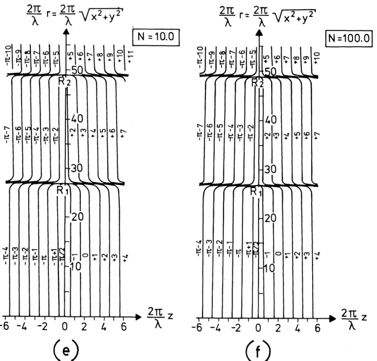
on a computer by employing Lommel's U functions whenI uN/vNI < 1 and Lommel's V function when I UN/VNI > 1. The results obtained are displayed in Figs. 3(a)-3(f) by the profiles
of cophasal surfaces in systems with different Fresnel
num-bers. In these figures, the curves are crowded in the region
near the dark rings of the Airy pattern. In order to avoid
overlapping, curves in those regions are displayed only
sche-matically. Actually, phase structure near the said dark rings
changed much more rapidly than is shown in Figs. 4(a)-4(f).
From these figures, it seems clear that the cophasal surfaces
near the focus are convex to the aperture and nearly
spher-ical.A further point of interest was a study of the curvature of
cophasal surfaces at the focus. To undertake this, Eq. (2.1)
was transformed into an implicit function with variables r andz, viz.,
G (z, r; ON) =
0,
(4.3)where
ON= constant. From this, the said curvature is
de-termined by
21XN=5.0
|
_T
-6 -4
-2
0
2
4
6
(c)
N=
2.01
--
_
T Z
-6 -4
-2
0
2
4
6
(d)
(Figure 3 continued overleaf)
Yajun Li
2TE r= 2TE VX_2,_y__2_"
X
X
t I
2TU r= 2 T
x
X
-VX~+
y2
A I t--I kz!Ito
U.,2
r= 2
X+Y
1
N =10.0
H IWt- o Cn CLfl
+ +0N
+ +
--:
n
(
4v
1§~~~~~~~~~~~~~~~~~
40
*-W U -.tC1)C CN M -S Lf(n tI
g
g1
+ +
4.44.
30
4 - I) '10-A0
I I
-..J A NJ(o1 LbII iII
'I- t1n1to
M "I CI
-S M N -I -I ill I I I I I I I I - I--6 -4
-2
O
2
4
6
FRF, 4. toV ,co a40
N
ItL
4
30
20
1c
C
4+IN =100.0I
0C I1 WI C1 Im .4(e)
(f)
Fig. 3. Profiles of cophasal surfaces in the immediate neighborhood of the focal plane in an F/3.5 system with different Fresnel numbers N.
OR1and OR2are radii of the first and the second dark rings in the Airy pattern.
=GzGr(Gzr + Grz) - (Gr)2
Gzz
- (Gz)
2Gr
o (4.4)(Gz2
+
Gr2)3/ r=O (4)= - -
K
(4.6)in which
G,
=G/OzG r = aG/8r, Gzr =d
2G/azar,.... After a lengthy derivation, omitted here, the result obtained can be expressed asf
(1
-1/16F
2)
(4.5)
If F
2>>1, the above relationship is reduced to
K r-f-1; then
the corresponding radius of curvature
is obtained, a result that indicates that the center of the radius of curvature is in the middle of the aperture. This theoretical outcome, which may be regarded as a fundamental property for focusing systems of any Fresnel numbers, is shown graphically in Fig. 1 by the dashed circular curve. This out-come is also in close agreement with the experimental results obtained in microwave optics, as reported by Farnell (see Figs. 2 and 3 of Ref. 14).
The complete phase distribution near the focal plane can be found by rotating Fig. 3 around the z axis. After this has been done, the curvature circle in this figure becomes a sphere
of radius f.
o
a
"
(N
I I II I I I I I-6 -4 -2
0
2
4
6
--
-MWdt-dtv t a . q M N 0 I I cc I V I -Y I.t
+ 1>1 ^nI
-X z
* 2
TE z
X
Vol. 2, No. 10/October 1985/J. Opt. Soc. Am. A 1683
The classical prediction concerning the cophasal surfaces
in the immediate neighborhood of the focus may be consideredas a special case of the present result [expression (4.6)]. This
is because the region in which the classical authors
3carried
out their calculations was limited by the first several dark ringsin the Airy pattern, which, when the Fresnel number is far
larger than unity, is rather small in comparison with a sphere
of radius f. As a result of the limitation of the region of
ob-servation, it was logical for the classical authors to conclude
that the cophasal surfaces in the immediate neighborhood of
the focus are almost plane.
5. PHASE ANOMALY
In the classical theory of focusing, phase anomaly near the
focus is an important subject that has attracted the attention
of many investigators during the many years past. After
numerous notable investigations, it is now generally accepted
0.5 1.0 Z/f
@-8°718!~
--,,-
I -,,
--'
(edge of the geometrical shadowf _ /2._________ _.________ ____ __
-
N
Z/f
I I I , ,II I I E)=6*I '1
6 eI§@NZ/f
0=44° II5N z/f 0=2 0 !N Z/fI
1 :
I
:,,
, I I,
,I
0=30'
-
---1.0 -0.5 A6N 0.5 1 0 Z/f
(a) N-=0 5
-1.0 -0.5 p5N 0.5 1.0 Z/ f 0= 80 7.8' \-(edg of th gemer_ a _ haow -1_ 2________ = =
'N z/f 0=6 I I I I I 1 I I I II I I I I 940 --6 N Z/f 6 N Z/f 0=20
I ,
, , |>
|
t6~N
Z / f
-3 01 -1.0 _ *6N 0.5 1.0 Z/fI
.I.
. . . _
0=0° -0.5 _ _ _ _ _ _ _ _ _ _ _ -_ T 0 -1.0 -0.5 0.5 1.0 Z/f -=80 7.8'0
(edge of the geometrical shadowf)-/ 2
Z/f
I, I I, L , , I,~~~~~~~I
I I I I I i I 0=60O
i6N Z/f , 56N Z/f I ' I I I 1 1 1 1 , I I I I I I I I I 0:20 j L5N Z/f 0-30' _ -1.0 -0.5 6N 0.5 1,0 Z/f(b) N=1.0
-1.0 -0.5 6N 0.5 1.0 Z/f - 8 7'.8 I I II I(ldge ot the geometrical shadow) -f12
'5N J Z/f 0=60 5N Z/f 6 N Z/f I, I I I, W
~~~~~~~~~I
I I I I I,, I 0=20 ,N z/f 0=30' _ _ __* _ - --- _----l.0
-
0.5\ A6N l.0 Z/ fQ
0
=0
\ \
N
(ax
is)
--if
(C)N=2.0
72_
_--
-(d) N=5.0
(Figure 4 continued overleaf)
-1.0 -0.5 Yajun Li
-1.0 -0.5 0 0i.5 1.0 Z/f
0=8° 7.8' i ! i i i I I
(edge of the geometrical shadowi \ - -/2
- A aN z/f 9=60 I I I I
,.~~~~
5N
~~Z/f
I @,,,
I
I,- <_X ",,,
i!
I,
,
i.
/
-
-, ---
,,,,
I, I,,,,---
.f
i
~~~~4N
z/f
9=20
- I.xJI Il II ! I A --- - f\_- - I---9=30'-1.0
-0.5
\ \
\p
0.5
1.0 Z/f
9=0* 1/ _-L~S --- -- -- ---( f 0
---- a _____ ,(e) N
=1O
-0.05 -0.025 0.025 0.05 Z/f --- N a &1 Z/ f 9=80 7.8s -. T *Ldlt2L L" m rica(1 shadow) I7/2
__ * * * 46,
~ ~ ~ ~
---9=60 1- -1--l
1 §_i_<_
1
i |--- ----e6N Z/f 9:20 o6N~~~~~~z/f
9)=30O' -0.05 \-0.0 2 5 : 0N 0.025 0.05 Z/fto consider the phase behavior as the observation point P
moves along a selected geometrical ray through the focus (seeFig. 1). If 0 is the angle between the axis and the selected
geometrical ray, then we have
N=
2F tan 0.
(5.1)
UN
By inserting the above formula into Eq. (2.1), we obtain
4F2U/2N
(1 UiN 2 cxUNON (UN, 0) = 1 F 2 N 1
+ -
tan2
0) (UN 0)(mod 2ir). (5.2)
In order to determine the linearity in the phase change
de-scribed by Eq. (5.2), we introduce a reference wave(geomet-rical wave). This wave has a linear phase property as
obser-vations are made in the region of illumination predicted by
geometrical optics and along a ray through the focus, viz.,
D(P)
=exp[-i(UNR
,)0
< 0 <
tan' (2F), (5.3)
where
0(UN, 0) =
-kR
when UN 1< O=
+kR
when
UN >O JHere k = 2-r/X is the wave number, and
R = (Z2
+ r2)1/2 =
khI-
1 1 4UN/2rN
2UNI sec 0is the distance from point P to the focus 0. The difference
A L
JT _ _ ___ _____
i-807 (edge of the geometricalshadow)
I IT if
A
IT (ax is) - 1-/2-(f)N100
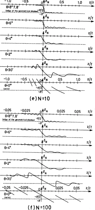
Fig. 4. Phase anomaly along geometrical rays through the focus in an F/3.5 system with different Fresnel numbers N. The angle 0 de-notes the inclination of the ray to the axis.
that -a converging spherical wave undergoes a rapid phase
change of 7r rad in passing through its focus.' This
phe-nomenon is not only observable in focused light fields
24 but
also in focused acoustic fields.In this section of the present study, the classical predictions
concerning phase anomaly near the focus are checked in
sys-tems of different Fresnel numbers. To this end, it is necessaryA
IT.T
.
.
.
.
.
.
.
0 2 4 6 8 10 12 14 ---. I I I . . , . . I I AhI l--1 ie I I I0-rt--- ---
----0=2°f-I I6I . , * I I , I I III_30' - 1N
K- , 3 -J 6=0 (axis)
_. ,__ I I |_L --- , _ - - I I -B K Io
0 2 4 6 8 10 12 14
Fig. 5. Difference between phase anomaly
AN
evaluated at the pointsz = -0.2f and z = +0.2f in an F/3.5 system. (5.4) (5.5) N N ,,,,-, - , ___ _) 1--11--'
a
IVol. 2, No. 10/October 1985/J. Opt. Soc. Am. A 1685 1 2 3 4 5 6 7 8 9 10 11 12 N 0 (axis) 0.1 0.2 0.3 0.4
N
0.5
(edge of the geometrical shadow)
I Fig. 6. Rapidity of the change of AN in the focus. (5.6)
+U4N
tan
201
Further evidence is provided by considering the following
two quantities. First,
A = WN(UN, O)z=-0.2f - N(UN, 0)z=+0.2f, (5.8)
-
a(UN,
0)- '
2
(mod 2r),
(5.7)
is called the phase anomaly along a geometrical ray. In order to compare this result with that given by the classical authors (see, e.g., Fig. 8.47 of Ref. 1), the same f number (i.e., F/3.5)
is now adopted, and the influence of the Fresnel number on
the phase anomaly is observed.
The results obtained from Eq. (5.7) are demonstrated in Fig. 4 for the same Fresnel numbers as those in Figs. 2 and 3. Each curve in Fig. 4 corresponds to a particular geometrical ray through the focus. Phase anomaly near the focus in a N = 100 focusing system [Fig. 4(f)] is essentially the same as the clas-sical result, in which 3
N(UN, 0) (phase anomaly along the axis) is a linear function of the z coordinate, except at the points of zero intensity; for the oblique rays, phase anomaly is an-tisymmetric to the focus and undergoes a rapid but continuous phase change of 7r rad as the rays pass through the focus. These properties, which are notable outcomes of the classical theory of the phase anomaly in the focus, disappear one by one with decreasing values of the Fresnel number N. Figures 4(e)
(N = 10) and 4(d) (N = 5) show that phase anomaly is no
longer antisymmetrical to the focus and that, along the axis
and between two adjacent transitions,
3N becomes a nonlinear function of the z coordinate. However, the change of aN near
the focus is still r rad. But this property is lost when the
Fresnel number is further decreased. Thus the classical
theory can no longer be used to predict correct results when the Fresnel number is of the order of unity or smaller [see Figs. 4(a), 4(b), and 4(c) for the cases of N = 0.5, 1, 21.
an index number expressing the total amount of the change
of
3N
between two points on the two sides of the focus; and,
second, a quantity concerning the rapidity of the change of
aN in the focus,'5viz.,
bN'(0
0)
=MaN
dUN\
7rN
1
dUN
z
-) o = 21+ 16F
2(sec 0
-1)],
0 < tan 0 < (2F)'-. (5.9)This result indicates that the rapidity of the phase-anomaly
change along a selected geometrical ray is directly proportionalto the Fresnel number of the diffracting aperture.
Under the condition F2>> 1, we have sec 0 - 1 0.5 tan2
0. We then obtain the following expression:
3
N'(O, 0)
= --[1
+
8(F tan
0)2],
2
0 < (F tan 0) < 0.5.
(5.10) The quantity A is plotted in Fig. 5 as a function of the
Fresnel number N. From this figure it is seen that the
phase-anomaly change in the focal point and along the edge
of the geometrical shadow attains 7r rad when N> 2, whereasphase anomaly along the axis attains the same amount of
variation when N 2 5. The rapidity of this variation [Eq.
(5.10)] is demonstrated in Fig. 6, from which it is seen that an appreciably rapid phase change occurs in the focus only whenN > 10. Therefore Gouy's prediction of the anomalous
propagation of phase in the focus, i.e., a converging spherical wave undergoes a rapid 7r rad phase change in passing through its focus, may describe phenomenon in focusing systems onlywhen their Fresnel numbers are considerably larger than
unity.
0 -10 -20 -30 -40 -50 -60 (89'2.T )WNUN, a) = ON(UN, a) -(UN, O),
4F21UN [ Yajun Li
6. CONCLUSIONS
In this paper, phase distribution near the focus is
demon-strated by a series of diagrams. It seems that if these results
are combined with the previous diagrams that show in detail
the structure of the field and the distribution of encircled
energy in the focal region,"1 12a comprehensive knowledge ofthe focused field would then be obtained. For this purpose,
the Fresnel numbers in Figs. 2-4 have been arranged in the
same way as those used in the previous investigations.
ACKNOWLEDGMENT
I wish to thank E. Wolf for numerous helpful discussions
concerning the subject matter of the present paper.
* Present address, Institute of Optical Sciences, National
Central University, Chungli, Taiwan 320, China.
REFERENCES
1. M. Born and E. Wolf, Principles of Optics, 6th ed. (Pergamon, Oxford, 1980), Sec. 8.8.
2. A. Rubinowicz, "On the anomalous propagation of phase in the focus," Phys. Rev. 54, 931-936 (1938).
3. E. H. Linfoot and E. Wolf, "Phase distribution near focus in an
aberration-free diffraction image," Proc. Phys. Soc. London 69, 823-832 (1956).
4. R. W. Boyd, "Intuitive explanation of the phase anomaly of fo-cused light beams," J. Opt. Soc. Am. 70, 877-880 (1980). 5. J. J. Stamnes, "Focusing of two-dimensional waves," J. Opt. Soc.
Am. 71, 15-31 (1981).
6. H. J. Erkkila and M. E. Rogers, "Diffracted field in the focal volume of a converging wave," J. Opt. Soc. Am. 71, 904-905 (1981).
7. J. J. Stamnes and B. Spjelkavik, "Focusing of small angular ap-erture in the Debye and Kirchhoff approximations," Opt. Com-mun. 40, 81-85 (1981).
8. E. Wolf and Y. Li, "Conditions for the validity of the Debye in-tegral representation of focused fields," Opt. Commun. 39, 205-210 (1981).
9. Y. Li and E. Wolf, "Focal shifts in diffracted converging spherical waves," Opt. Commun. 39, 211-215 (1981).
10. Y. Li, "Dependence of the focal shift on Fresnel number and f number," J. Opt. Soc. Am. 72, 770-774 (1982).
11. Y. Li, "Encircled energy for systems of different Fresnel num-bers," Optik 64, 207-218 (1983).
12. Y. Li and E. Wolf, "Three-dimensional intensity distribution near the focus in systems of different Fresnel numbers," J. Opt. Soc. Am. A 1, 801-808 (1984).
13. G. W. Watson, A Treatise on the Theory of Bessel Functions, 2nd ed. (Cambridge U. Press, London, 1962), Sec. 16.5.
14. G. W. Farnell, "Measured phase distribution in the image space of a microwave lens," Can. J. Phys. 36, 935-943 (1958). 15. Y. Li, "The anomalous propagation of phase in the focus: a