IEEE TRANSACTIONS ON MAGNETICS, VOL. 43, NO. 6, JUNE 2007 2585
Magneto-Electrodynamical Modeling and Design of a Microspeaker
Used for Mobile Phones With Considerations of Diaphragm
Corrugation and Air Closures
Paul C.-P. Chao
1, Chi-Wei Chiu
1, and Yuan Hsu-Pang
2Department of Electrical and Control Engineering, National Chiao Tung University, Hsinchu 300, Taiwan, R.O.C. Department of Mechanical Engineering, R&D Center for Membrane Technology, Chung-Yuan Christian University,
Chungli 320, Taiwan, R.O.C.
Recent design trends for modern mobile phones are evolving to be miniaturized and versatile sounds in quality. To these ends, a microspeaker with a corrugated diaphragm is employed to broaden the sound frequency range. Due to the fact that diaphragm corru-gation and air closures were not considered in any past studies, this study presents comprehensive modeling with the consideration of diaphragm corrugations and air closures. It starts with the modeling on the subsystems of the voice coil motor (VCM) in the speaker. The magnetic field of the VCM is modeled by one set of finite elements, while the corrugated diaphragm is modeled by another set of finite elements. In addition, the air closures above or below the diaphragm are modeled by the third group of finite elements based on basic acoustics. Simulations are conducted with and without air closures. It is found that: 1) the speaker with 45 corrugation exhibits overall higher (better) sound pressure levels (SPLs), while 2) the 75 corrugation leads to unsatisfied, low SPLs below 1 kHz and two undesired antiresonances at higher frequencies. The theoretical findings are successfully validated by experiments.
Index Terms—Air closure, cell phones, diaphragm corrugation, microspeakers, voice coil motor (VCM).
I. INTRODUCTION
T
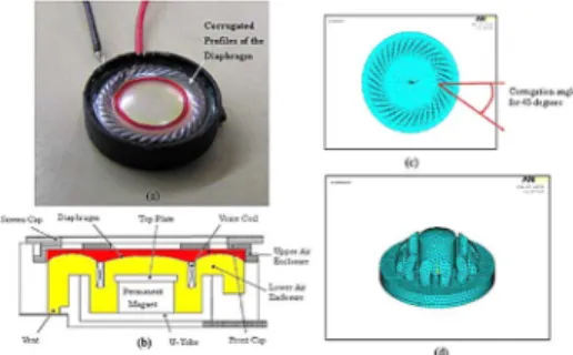
O RESPOND to recent demands for miniaturization and high sound quality for commercial mobile phones, the microspeakers in mobile phones are expected to have signifi-cant reduction in size and also provide broad frequency ranges of realistic sound responses. Toward the aforementioned ends, a microspeaker with a vibrating small-sized diaphragm that is responsible for generating sound is commonly employed. A schematic of the microspeaker is shown in Fig. 1(a), which consists mainly of a diaphragm and a voice coil motor (VCM) attached at the bottom surface of the diaphragm. A magnetic field is generated between the top plate and the U-yoke. Having applied voltage to the VCM, the electromagnetic interaction between the magnetic field and VCM current would generate forces to drive the diaphragm to vibrate and then generate sound.Conventional macro-sized loudspeakers have been modeled and analyzed via lumped models to a mature stage [1]. However, as the commercial demand increases for small-sized speakers as used in mobile phones, the lumped model is not sufficient to accurately predict the dynamic performance of a microspeaker at high frequencies, which are believed to be heavily affected by diaphragm corrugation and the air closures surrounding it. Therefore, the approach adopting a distributed parameter model and the finite-element analysis (FEA) is required. Some works [2], [3] conducted FEA modeling on the diaphragm, along with consideration of the magneto-electromechanical couplings be-tween vibrating diaphragm, coils, and the magnetic flux induced by the surrounding magnets.
The aforementioned studies, however, lack consideration of commonly seen diaphragm corrugations as shown in Fig. 1(a),
Digital Object Identifier 10.1109/TMAG.2007.892871
Color versions of one or more of the figures in this paper are available online at http://ieeexplore.ieee.org.
Fig. 1. (a) Microspeaker with corrugated diaphragm. (b) Schematic cross-sec-tion view on the microspeaker. (c) The diaphragm in finite elements with cor-rugation angle 45 . (d) Finite-element model of the air closures.
which are employed in most commercialized mobile speakers to enhance high-frequency sensitivities to required levels. In this way, a fairly flat frequency response (compared to the generic frequency response of a second-order vibratory system) over a broad range can be achieved to avoid sound distortion to human ears. With the main goal of confirming the effectiveness and distilling design guidelines of diaphragm corrugation, theoret-ical modeling and experiments are conducted in this study. The modeling is completed through finite elements on subsystems: VCM, air closures, and diaphragm. The corrugation angle 45 is found to the best of others and the corresponding frequency response is verified via experimental study.
II. MATHEMATICALMODEL
This section presents electromagnetic, mechanical, and acoustical modeling for the respective subsystems in a micros-peaker—VCM, corrugated diaphragm, and air closure.
A. Voice Coil Motor
The electromagnetic system of the microspeaker, as shown schematically in Fig. 1(b), is composed of a VCM, a top plate, a permanent magnet, and a U-yoke. With voltage applied to VCM, the current in VCM is generated to run through the magnetic
2586 IEEE TRANSACTIONS ON MAGNETICS, VOL. 43, NO. 6, JUNE 2007
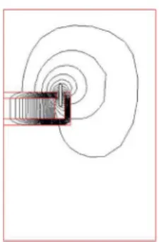
Fig. 2. Simulated magnetic flux intensity distribution in the axisymmetric domain.
field. The interaction between the VCM current and the mag-netic field results in a Lorentz force along the axial direction of the diaphragm and in the form of
(1)
where and are VCM current and wire length, respectively, while is the magnetic flux density in the gap between the top plate and the U-yoke as shown in Figs. 1(a) and 2. This den-sity is solved based on Maxwell’s equations, which is realized by finite-element modeling with ANSYS [5]. It is assumed, as shown in Fig. 1(b), that the magnetic system of the microspeaker is in an annular axisymmetric structure. Fig. 2 presents the sim-ulated magnetic flux intensity distribution. With solved flux in hand, the current equation can be derived, which is
(2)
where , and denote the applied voltage, the resistance, the inductance, and the axial velocity of the VCM, respectively, and the last term in (2) results from back electromotive force (EMF). is the flux density along the center line of the gap between the top plate and the U-yoke as shown in Figs. 1(b) and 2, which is identified offline based on preliminary experiments and curve fitting.
B. Corrugated Diaphragm
Finite-element modeling (FEM) using ANSYS is also adopted for subsequent mechanical vibration analysis on the corrugated diaphragm. Fig. 1(c) shows the established model from the top view, where the corrugation has a baseline 45 with respect to the radial axis of the diaphragm. The equations of motion of the corrugated diaphragm can be extracted from the finite elements as
(3)
where , and denote the mass, damping, stiffness ma-trices, and an axial electromagnetic force vector exerted by the VCM, respectively. The axial force owns nonzero compo-nents corresponding to the axial direction and the nodes along the circumference of VCM coils. To reduce computation load, the modal transformation analysis [4] is next employed to re-duce the sizes of the matrices in (3) by first transforming the
dynamics of the system into those in modal space and then con-sidering only the first few modes to 20 kHz, the upper limit of human audibility.
C. Air Closures
As illustrated by Fig. 1(b), air enclosures exist above (illus-trated by the red area in color or the darkly shaded one in gray) and below (yellow in color or the lightly shaded one in gray) the vibrating diaphragm. The dynamics of the air inside two clo-sures are modeled by the third sets of finite elements, and bound-aries are assumed solid-fluid interactions. The process of mod-eling on the air are based on the lossless acoustic wave equation
(4)
where is the air pressure while is sound speed, and starts with discretizing the closures through Galerkin decomposition [4]. It finally arrives at the system equation
(5)
where , and denote the derived mass, damping, and stiffness matrices of the air. Also, is the air density; R is the coupling matrix between diaphragm surface and air; is the vector containing nodal displacements at the diaphragm surface. The fourth term in (5) reflects the dynamical effects of the vibrating diaphragm on the air closures. On the other hand, (3) is modified to be
(6)
where the last term on the left-hand side captures dynamical ef-fects of the air closures on the vibrating diaphragm. With (2), (5), and (6) in hand, the dynamics of the microspeaker can be simulated. Finally, to obtain the sound pressure level (SPL) at the point away from the center of the vibrating diaphragm by some distance, finite elements are constructed above the top cover of the speaker as shown in Fig. 1(d). In this way, the SPL can be calculated by
(7)
where is the rms value of the pressure calculated at the point interested while is the reference, ambient sound pres-sure of Pa.
III. SIMULATION ANDEXPERIMENTALSTUDY
Simulation and experiment are conducted to understand dy-namic and acoustic insights of the considered microspeaker, and then distill design guidelines for the corrugation angle on the diaphragm. To these ends, the material properties of the di-aphragm are first acquired. Its Young’s modulus is 8.08 10 Pa; Poisson’s Ratio is 0.25; and density is 1360 kg/m . The VCM is made of copper, and Table I lists its identified electrical prop-erties. An experimental system, as illustrated in Fig. 3, is set up in an anechoic chamber, where it consists of a microphone to measure the sound pressure generated by the microspeaker, a Sunlight-1600 electroacoustics analyzer to acquire the mea-surements and convert them to SPLs, and a baffle screen to fix
CHAO et al.: MAGNETO-ELECTRODYNAMICAL MODELING AND DESIGN OF A MICROSPEAKER 2587
TABLE I
IDENTIFIEDELECTRICALPROPERTIES OF THEVCM
Fig. 3. Experimental setup.
Fig. 4. (a) Simulated and experimental responses with various corrugation an-gles but without air closures modeled. (b) Responses with air closures and 45 corrugation angle.
the measuring microphone. The anechoic chamber provides an environment nearly without sound reflection, and then results in extremely low background sound noise and vibration.
Considering no air closures first, the SPLs at the point 5 cm from the diaphragm center are computed based on the methods in Section II and shown in Fig. 4(a), where it is seen that three different corrugation angles of 15 , 45 , and 75 are considered. Also seen from this figure is that they all render similar SPLs up to the midrange of the audible frequencies, around 4 kHz. However, the one with 75 corrugation angle has the smallest response above 4 kHz than the others—the least sensitivity, and also exhibits two antiresonances around 9 k and 10.5 kHz. Based on the computation by ANSYS, these two antiresonances cor-respond to those two axisymmetric mode shapes—the 4th and 14th—that have an almost motionless central circular area of the diaphragm, as shown in Fig. 4(a). Also depicted in Fig. 4(a), are the SPLs without diaphragm corrugation. The SPLs without cor-rugation appear to have smaller responses and higher first res-onances than the others due to larger axial stiffness. It can also
be seen that the cases with corrugation angles 15 and 45 lead to flatter SPL curves than that without corrugation, validating the well-known merit of the corrugation—lessening sound dis-tortion. Furthermore, the diaphragm with 45 corrugation ren-ders slightly higher (better) responses over the entire audible frequency range.
The experimentally measured SPLs are shown in both Fig. 4(a) and (b) for comparison with simulations in solid curves. It can be seen from Fig. 4(a) that general closeness is present between the theoretical response with diaphragm corrugation and the experimental counterparts up to the midfre-quency of 4 kHz, indicating adequate validity of the established theoretical model. However, an obvious discrepancy appears above 4 kHz, which, based on the basic theory of a speaker, should be due to the lack of consideration of air enclosures above and below the vibrating diaphragm in the structure of the microspeaker as shown in Fig. 1(b). Fig. 4(b) shows the simulated responses with air closures and 45 corrugated diaphragm considered. It is seen from this figure that the simu-lated response is very close to the experimental counterparts for a realistic speaker with a 45 -corrugated diaphragm, especially in high-frequency ranges—around 10 kHz. This validates the effectiveness of the theoretical model established in this study.
IV. CONCLUSION
An effective model for a microspeaker with a corrugated diaphragm is successfully established in this study via sub-modelings on electromagnetic, mechanical, and acoustical subsystems. Closeness is found between simulated and experi-mental responses for the case with a 45 corrugation angle for the speaker diaphragm. Among three considered corrugation angles of 15 , 45 , and 75 , the diaphragm with 45 corruga-tion exhibits the overall highest (best) SPLs.
ACKNOWLEDGMENT
This work was supported in part by the National Science Council of Taiwan, R.O.C., under Grant 95-2622-E-009-014-CC3, and in part by the Center-of-Excellence Program on Mem-brane Technology, the Ministry of Education, Taiwan, R.O.C.
REFERENCES
[1] K. M. Al-Ali, A. K. Packard, and B. H. Tongue, “Lumped-parameter modeling of vented-boxloudspeakers,” in Proc. Amer. Contr. Conf., Chicago, IL, 2000, pp. 023–3027.
[2] G. Y. Hwang, H. G. Kim, S. M. Hwang, and B. S. Kang, “Analysis of harmonic distortion due to uneven magnetic filed in a microspeaker used for mobile phones,” IEEE Trans. Magn., vol. 38, no. 5, pp. 2376–2378, Sep. 2002.
[3] S. M. Hwang, H. J. Lee, K. S. Hong, B. S. Kang, and G. Y. Hwang, “New development of combined permanent-magnet type micros-peakers used for cellular phones,” IEEE Trans. Magn., vol. 41, no. 5, pp. 2000–2003, May 2005.
[4] L. Meirovitch, Fundamentals of Vibrations. Singapore: Mc-Graw-Hill, 2001.
[5] ANSYS Structural Menu. Philadelphia, PA, 2005.
Manuscript received October 30, 2006; revised February 7, 2007 (e-mail: pchao@mail.nctu.edu.tw).