IEEE PHOTONICS TECHNOLOGY LETTERS, VOL. 22, NO. 6, MARCH 15, 2010 419
A Novel Passive Optical Network Architecture
Supporting Seamless Integration of RoF
and OFDMA Signals
Yu-Min Lin, Po-Lung Tien, Maria C. Yuang, Steven S. W. Lee, Jason (Jyehong) Chen, Shing-Yu Chen,
Yi-Min Huang, Ju-Lin Shih, and Chih-Hung Hsu
Abstract—In this letter, we propose a novel passive optical network (PON) architecture supporting radio-over-fiber signals and orthogonal frequency-division multiple access (OFDMA) PON signals. The architecture transports upstream multiple remote antenna’s wireless signals using only one upstream wavelength. In addition, the windowed-orthogonal frequency-di-vision-multiplexing technique is employed to mitigate interference during the integration process. Experimental results shows that 10-Gb/s OFDMA and three radio-frequency signals at 2.1 GHz are successfully transmitted over 20-km single-mode fiber in a 32-optical-network-unit PON.
Index Terms—Optical fiber communication, optical modulation, orthogonal frequency-division multiple access (OFDMA), passive optical network (PON), radio frequency (RF), radio-over-fiber (RoF).
I. INTRODUCTION
B
ROADBAND wireless access systems have been success-fully exploited to provide ubiquitous high-speed connec-tivity to end users. Next-generation passive optical networks (PONs) are thus expected to seamlessly transport wireless sig-nals [1] to reduce the deploying cost while taking advantage of huge capacity of optical fiber. However, supporting multiple re-mote antenna ports in one trunk fiber gives rise to the optical beat interference (OBI) problem. To alleviate the problem, the approaches [2] exploit either wavelength-division-multiplexing (WDM)–PON or multiple upstream lasers at specially selected widely apart wavelengths, which are relatively expensive and impractical.In this letter, we propose a new orthogonal frequency-divi-sion multiple access (OFDMA)-PON architecture without using WDM lasers. The architecture enables integration of broadband transport and wireless radio-frequency (RF) signals from mul-tiple remote antennas. The integration unfortunately gives rise
Manuscript received September 07, 2009; revised December 06, 2009; ac-cepted December 30, 2009. First published January 29, 2010; current version published February 26, 2010.
Y.-M. Lin, S.-Y. Chen, and C.-H. Hsu are with the Information and Com-munications Research Laboratories, Industrial Technology Research Institute, Hsinchu 31040, Taiwan.
P.-L. Tien, M. C. Yuang, J. Chen, Y.-M. Huang, and J.-L. Shih are with the Department of Communications Engineering/Computer Science/Photonics, Na-tional Chiao Tung University, Hsinchu 30010, Taiwan (e-mail: mcyuang@csie. nctu.edu.tw).
S. S. W. Lee is with the Department of Communications Engineering, Na-tional Chung Cheng University, Chiayi 62102, Taiwan.
Color versions of one or more of the figures in this letter are available online at http://ieeexplore.ieee.org.
Digital Object Identifier 10.1109/LPT.2010.2040270
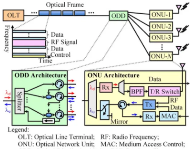
Fig. 1. OFDMA-PON architecture.
to the OFDMA signal interference to RF signals despite that several OFDMA subcarriers around the radio band are disabled. In this letter, we adopt a windowing technique at the OFDMA transmitter to mitigate the interference. Experimental results demonstrate that 10-Gb/s OFDMA signals and three RF sig-nals at 2.1 GHz are successfully transmitted over 20-km single-mode fiber (SMF) in the new PON with 32 optical network units (ONUs).
II. NETWORKARCHITECTURE
The proposed OFDMA-PON [3], [4] (see Fig. 1) connects multiple ONUs to the optical line terminal (OLT) through an optical distribution node (ODD). The ODD is composed of one short section of drop fiber for each ONU and a set of optical circulators to direct signals among ONUs and OLT. The OFDMA-PON uses two wavelengths, and , to convey downstream and upstream data, respectively. To send data downstream, the splitter in ODD generates multiple signal copies, each of which passes a circulator before reaching the destined ONU.
For upstream data, ONU-1 first sends its upstream data and control information to ONU-2 through circulators. Upon having received data and control information on , the next ONU de-termines the subcarrier on which its upstream data is carried, and regenerates the OFDMA signal and sends it to the next ONU down the line. Finally, at ONU- , the upstream wavelength is passed to OLT through the ODD. Moreover, the OFDMA-PON includes a 1-by-2 optical switch at each ONU’s (upstream) to protect from accidental blackout or shutdown of ONUs.
420 IEEE PHOTONICS TECHNOLOGY LETTERS, VOL. 22, NO. 6, MARCH 15, 2010
Fig. 2. RoF-signal overlay with OFDMA-PON data.
Fig. 3. Spectrum of radio band.
We illustrate in Fig. 2 that the wireless RF signals received by two remote antennas at ONU-1 and ONU-2, respectively, are overlaid with the broadband OFDMA signals. First, the wire-less signal is frequency-shifted to the allocated band by a mixer, an oscillator, and a bandpass filter (BPF1). The shifted signal is then combined with the upstream OFDMA signal, which is together sent by the directed modulated laser to ONU-2. Upon receiving, ONU-2 first splits the received signal into two paths. The first path is for the regeneration of the upstream OFDMA PON signal. The process includes analog-to-digital conversion, original OFDMA demodulation, control-channel identification, adding of local data, the modulating OFDMA signal regener-ation, and finally digital-to-analog conversion. For the other path, the system uses a bandpass filter BPF2 on the allocated radio band to remove the OFDMA signal but preserving all pre-vious wireless signals intact. The RF combiner then combines the local antenna’s signal from BPF1 with the previous ONU’s wireless signals from BPF2. Finally, the system integrates the radio signal with the OFDMA PON signal via an RF directional coupler before driving the upstream laser.
III. WINDOWINGMETHOD TOREDUCEINTERFERENCE
Due to the integration, the signal orthogonality can no longer be assured, resulting in the interference of OFDMA signal to RF signal. As shown in Fig. 3, the sidelobes of OFDMA subcarriers near the radio band determine the wireless signal’s signal-to-in-terference ratio. To mitigate the insignal-to-in-terference by reducing the sidelobes, we employ time-domain windowing [5] of the or-thogonal frequency-division-multiplexing (OFDM) symbol at the transmitter side.
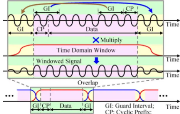
Fig. 4. Design principle of the windowing method.
The design principle behind the windowing technique is to reduce the degree of waveform discontinuity between adjacent OFDM symbols to suppress the out of band frequency compo-nent. We illustrate in Fig. 4 that the waveform of a subcarrier in the OFDM symbol is multiplied by a time-domain window to smooth the signal gradually around symbol boundaries. No-tice that the employed window must not affect the original FFT period of the OFDM system. Therefore, a guard interval (GI), which is the cyclic extensions of the original signals, is added before and after the original OFDM samples. Note that the front GI can be overlapped with the rear GI of the preceding symbol, thereby reducing the overhead from 2*GI to only GI points.
In this work, we use the Nyquist windowing method, de-noted as the second-order polynomial window (SOCW) [5]. The strength of the method is that its parameters can be optimized to suppress interference for a specific spectrum range. The Nyquist window can be generally expressed as follows:
(1)
where is referred to as the
normalized elementary function, is the roll-off factor, and is the OFDM symbol duration before adding the GI. Larger means longer GI and hence low bandwidth efficiency. In the work, we choose such that the GI overhead is limited to 5% (28 points). The resulting spectrum of windowed-OFDMA signal is shown in Fig. 3. It is obvious that the sidelobes in the radio bandwidth are lower by 1~3 dB when compared with traditional OFDMA spectrum.
IV. TESTBEDEXPERIMENTATION
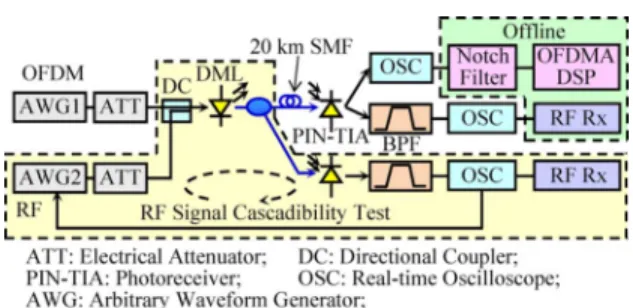
In the experiment shown in Fig. 5, the OFDM signal, which occupies 0.1- to 2.7-GHz bandwidth, is generated by an arbi-trary waveform generator (AWG) with 10-GHz sampling rate. The inverse fast Fourier transform (IFFT) size is 512 points, from which 16-quadrature amplitude modulation (QAM) encoded 128 subcarriers are used for data transmission. The cyclic prefix is 8 points and the GI for the SOCW is 28 points. The allocated radio band is 200 MHz in width at frequency 2160 MHz to accommodate multiple wireless signals. Three
LIN et al.: NOVEL PON ARCHITECTURE SUPPORTING SEAMLESS INTEGRATION OF RoF AND OFDMA SIGNALS 421
Fig. 5. Experimental setup.
Fig. 6. RF signal’s performance with respect to the driving power.
20-MHz WiMAX RF signal at 2100, 2160, and 2220 MHz, which are generated by AWG2 are used for the upstream test.
The experiment consists of two parts. OFDM and RF are first combined to drive a 3-dBm output power, 1550-nm direct modulated laser module. For the first part (a direct link test), a real-time scope captures the signal for offline signal demodula-tion. Over 1 million bits are compared before and after the link to obtain bit-error-rate (BER) results. A digital 200-MHz notch filter at 2160 MHz is used to remove the RF signals before the OFDM receiver. For the second part, we assess the performance of the RF signal via an offline recirculating loop experiment. After RF signals are extracted, a real-time scope captures and stores a section of waveform at a 12.5-GHz sampling rate in a file. The stored waveform is resampled to 10 GHz by a digital signal processing (DSP) program and fed to the AWG2 for the next hop transmission. For each hop, we load different OFDM signals to AWG1 so that each hop’s interferences are not corre-lated. We can thus emulate the accumulated interference to RF signal from ONU-1 to ONU-32.
Define the power ratio (PR) as the OFDMA signal’s driving power to the wireless signal’s, assuming the overall modulation index is optimized in a weakly clipping condition. We show in Fig. 6 that the RF signal’s signal-to-noise ratio (SNR) is dom-inated by the PR value and received power level. Although we intentionally zero 10 subcarriers for RF signal transmission, the inevitable OFDM sidelobes still affect the RF signal’s quality. The windowing method provides 0.5- to 1.3-dB improvement on the RF signal’s SNR. The inset of Fig. 6 shows the RF spec-trum under PR dB. We show in Fig. 7 that the receiver sensitivity for BER , which is the error-free limit with forward error correction (FEC), is 15.3 dBm at PR dB and 0.5-dB penalty is observed if RF signal is increased to 0-dB PR. Note that a better sensitivity can be achieved by using the avalanche photodiode (APD)-based photoreceiver instead of the PIN-based receiver in our experiment. After the 20-km fiber
Fig. 7. OFDM BER curve under different PR settings.
Fig. 8. RF signal’s SNR in upstream path.
transmission, the receiver sensitivity is degraded by 1.2 dB to 13.6 dBm. The fiber penalty comes from the laser diode’s chirp effect. The OFDM constellation diagram is displayed in the inset of Fig. 7. Given an optical received power of 13 dBm at ONU and 15 dBm at OLT, as shown in Fig. 8, the SNR of RF signal degrades as the node number increases due to the interference from OFDM signal’s sidelobes and optical–elec-trical–optical (O-E-O) conversion noise. If PR is equal to 1 dB, the SNR of the RF signal can still be above 16 dB (quadra-ture phase-shift keying (QPSK) error-free bound) after passing through 32 ONUs and a 20-km SMF.
V. CONCLUSION
We have proposed an OFDMA-PON architecture that in-tegrates 10-Gb/s OFDMA and three wireless signals using a windowing method to reduce interference. Experimental results show that after-coding direct-detection receiver sensitivity of OFDMA over a 20-km fiber is 13.6 dBm. Under a PR of 1 dB and received power of 13 dBm at each ONU, the RF signal can be relayed in a 32 ONU’s chain and recovered at OLT successfully.
REFERENCES
[1] D. Qian, J. Hu, P. N. Ji, T. Wang, and M. Cvijetic, “10-Gb/s OFDMA-PON for delivery of heterogeneous services,” in Proc.
IEEE/OSA OFC, 2008, Paper OWH4.
[2] M. Bakaul, A. Nirmalathas, C. Lim, D. Novak, and R. Waterhouse, “Hybrid multiplexing of multiband optical access technologies towards an integrated DWDM network,” IEEE Photon. Technol. Lett., vol. 18, no. 21, pp. 2311–2313, Nov. 1, 2006.
[3] P. Tien, Y. Lin, and M. Yuang, “A novel OFDM-PON architecture to-ward seamless broadband and wireless integration,” in Proc. IEEE/OSA
OFC, 2009, Paper OMV2.
[4] Y. Lin et al., “A novel optical access network architecture supporting seamless integration of RoF and OFDMA signals,” in Proc. IEEE/OSA
ECOC, 2009, Paper P6.13.
[5] Z. Yang, H. Zhang, D. Yuan, Z. Bai, and K. Kwak, “A novel Nyquist window for OFDM-based cognitive radio systems,” in Proc. Cognitive
Radio Oriented Wireless Networks and Communicaitons (CrownCom 2008), May 2008.