An Optimal and Adaptive Design of
the Feedforward Motion Controller
Syh-Shiuh Yeh and Pau-Lo Hsu,
Member, IEEEAbstract—The zero phase error tracking controller (ZPETC) in
motion control, as proposed by Tomizuka et al., renders the desir-able zero phase error, but with a limited gain response. Moreover, a ZPETC, which is basically in a feedforward control structure, is very sensitive to modeling error. To improve the tracking accuracy of the ZPETC, this paper presents an optimal ZPETC design with a concise polynomial digital prefilter (DPF). The parameters of this well-designed DPF are obtained through the derivedL2-norm optimization. By cascading the developed DPF to the ZPETC, the resultant optimal ZPETC greatly improves the bandwidth of the tracking control systems while maintaining the zero phase error. Compared with other optimal approaches, the present design leads to much simpler procedures and fewer computations. Furthermore, the proposed optimal ZPETC can be adequately implemented as an adaptive ZPETC by including real-time estimation technique to cope with the external load perturbation and parameter variation. Compared with the other adaptive approaches, the optimal concept is used in the present adaptive ZPETC, and it also renders more accurate results because of its improved magnitude response. Experimental results on a dc servo table with different controllers indicate that when there is no loading, the present optimal ZPETC achieves the best tracking performance. Moreover, the adaptive ZPETC achieves the most satisfactory results when an external load is applied.
Index Terms— Adaptive control, feedforward control, motion
control, optimal control.
I. INTRODUCTION
T
HE zero phase error tracking controller (ZPETC) feedforward controller design method was proposed by Tomizuka [1] to improve tracking accuracy in motion control. Basically, the design of the ZPETC controller directly cancels the stable poles and well-damped zeros in the position feedback loop and compensates for the unstable and lightly damped zeros to achieve both the zero phase error and a unity dc gain frequency response. However, the tracking accuracy of the controller design with zero phase error only is limited and a sufficient bandwidth in gain responses is desirable. Moreover, since the ZPETC design is obtained via the pole–zero cancellation based on the system model, any external load perturbation or parameters varying in the position feedback loop may seriously degrade control performance, and an adaptive ZPETC is, thus, crucial in real applications.Recently, several optimal ZPETC [7]–[10], modified ZPETC [11]–[17], and ZPETC designs based on new modeling
Manuscript received September 29, 1997; revised October 26, 1998. Rec-ommended by Technical Editor K. Ohnishi. This work was supported by the National Science Council, R.O.C., under Contract NSC 84-2512-S-009-006.
The authors are with the Department of Electrical and Control Engineering, National Chiao Tung University, Hsinchu, 300 Taiwan, R.O.C.
Publisher Item Identifier S 1083-4435(99)09963-9.
[18], [19] design methods have been proposed. However, in addition to the improved control performance, those newly developed methods involve either less compensation for all undesired zeros or heavy computations. Moreover, due to the influence of external load perturbation and varying parameters in real applications, performance of feedforward controllers in motion control systems is, thus, degraded. Some suitable feedback loop control algorithms [5], [6] and adaptive ZPETC [2]–[4] have been proposed to improve the degraded tracking performance. In order to gain good frequency responses for tracking control systems and reduce the calculation time for controllers, a DPF in a concise structure to maintain the control system with zero phase error and achieve a significantly improved bandwidth in the gain frequency response is proposed in this paper. The parameters of the digital prefilter (DPF) are obtained with the -norm optimization in the frequency domain, and this leads to the proposed optimal ZPETC. The detailed derivation is also provided in the Appendix.
In this paper, because the proposed optimal ZPETC is con-structed with a simple-structured DPF, it can be implemented more efficiently in real time with the constant covariance trace recursive least-square (RLS) parameter estimation algorithm [20]. The proposed adaptive ZPETC has been successfully applied to a dc servo motor tracking control system to achieve real-time estimation and compensation when an external load was applied.
This paper is organized as follows. The optimal ZPETC feedforward controller is derived in Section II. The adaptive ZPETC tracking control structure is discussed in Section III. The implementation of the optimal and adaptive ZPETC on a dc servo motor is described in Sections IV and V, and conclusions are given in Section VI.
The following notations are used throughout this paper: set of real numbers;
set of complex numbers;
real coefficient polynomial function;
Fig. 1. 2-DOF tracking control system.
II. OPTIMAL ZPETC DESIGN
The general two-degrees-of-freedom (2-DOF) controller de-sign for a tracking control system is shown in Fig. 1. The unstable and lightly damped zeros in the position feedback loop are called the unacceptable zeros; the stable and well-damped zeros in the position feedback loop are called the acceptable zeros. The feedforward controller is denoted as and the position feedback loop transfer function is represented as
(1) where
polynomials with acceptable zeros
polynomials with unacceptable zeros and
A. DPF Design
The ZPETC was originally designed to achieve zero phase error with a unity dc gain [1]. In order to improve the frequency response of the tracking control system as shown in Fig. 1, a feedforward controller designed with a DPF was proposed by Xia and Menq [9] and Menq and Chen [13] as
(2) Thus, the transfer function of the whole control system becomes
(3)
Fig. 2. The adaptive ZPETC tracking control system.
Fig. 3. Hardware layout of the dc servo motor tracking control system.
where the tracking error caused by the polynomial
is expected to be further compensated for by the DPF To compensate for the undesirable polynomial the concerns of magnitude and phase responses of
the DPF can be designed separately as
(4)
where the first part of the DPF achieves a
desirable magnitude response, and the second part of the
DPF compensates for the phase error to achieve
zero phase error. As proposed by Tomizuka [1], the DPF can be directly obtained from the ZPETC design method as
(5)
In order to further improve the gain response and maintain the zero phase error property in the ZPETC control system, the
DPF must also be designed with a zero phase
shift response. Accordingly, the polynomial functions in the set with zero phase shift frequency response [7], [16],
[21] are proposed here for the DPF as
(6)
where is the order of DPF and is the number
By substituting (5) and (6) into (4), the DOF is obtained as
(7) Moreover, by substituting (7) into (3), the control system
transfer function becomes
(8) or equivalently represented as
(9)
where is the coefficient of the polynomial
corresponding to the order In order to maintain the unity dc gain response, the constraint
of is required for the DPF design.
If the condition and the constraint
are satisfied, the feedforward controller according to (7) and (2) is
(10) which is the same as the original ZPETC design [1]. B. Norm Optimization for the DPF
Define the error function as
or
For the DPF its parameters
can be obtained by minimizing the norm of the error function in the frequency domain as
(11)
where and is the sampling period. To emphasize
the dominant component of signals, a general weighting func-tion can be included in (11). The constraint of unity dc gain can be denoted as
(12) In order to obtain the -norm optimal solution for the
polynomial parameters, the Lagrange
method is employed here and its detailed derivations are described in the Appendix. The optimal parameter vector
of the DPF is obtained as
(13) where definitions are given at the bottom of the page. Thus, the optimal ZPETC feedforward controller is obtained as
(14) Although the present optimal parameters solved by (13) is similar to the results proposed by Xia and Menq [9], the
present calculation of matrices from and
in (13) are greatly simplified. Note that the present matrix requires only one addition of a cosine function, but Xia and Menq’s approach requires multiplications of cosine functions for each element. Therefore, the present optimal ZPETC can be implemented more efficiently.
III. ADAPTIVE ZPETC DESIGN
Based on the proposed optimal ZPETC design, we will extend it to the adaptive ZPETC when system parameter variation exists or when external loading is applied in real applications. Since the present DPF is in a very simple structure, the derived optimal ZPETC can, thus, be directly implemented as the adaptive ZPETC for the DC servo table in real motion control.
As shown in Fig. 2, the adaptive ZPETC tracking control system includes three parts as follows: the position feedback
..
Fig. 4. The magnitude response of optimal ZPETC tracking control system compared with ZPETC tracking control system (——: optimal ZPETC; -- -- -- --: ZPETC).
loop, the parameter estimation and the feedforward controller with parameter adaptation. The position feedback loop is usually combined with a proportional gain controller and the controlled plant which includes the velocity loop of the dc servo motor and the mechanical system. Since the velocity loop for the dc servo motor with a lower order mathematical model is more sensitive to the external load perturbation than the position feedback loop, the velocity loop adaptive control structure is, thus, used in this paper as shown in Fig. 2. The general design conditions for the adaptive ZPETC tracking control system are as follows.
1) The position feedback loop is internally stable [22] during the adaptive processing.
2) The gain of the position controller is fixed. 3) The parameters of the velocity loop are slowly varied. 4) The gain of the mechanical system is fixed.
The control input signal and the velocity output signal are used for the present parameter estimation. By applying the adaptive ZPETC to motion control systems, the discrete velocity loop can be on-line identified as
and the controlled plant is obtained as
(15) where is the combined gain including the D/A gain, the transmission gain, and the tachometer feedback gain. is the sampling interval. The position loop transfer function is obtained as
and the adaptive ZPETC is designed as
(16)
where is a one-step-delay operator and
and are the desired output and the reference input of the optimal ZPETC, respectively. is solved by (13). Note that, in implementation, is recognized as unacceptable polynomial in (16) to avoid unstable pole–zero cancellation.
Considering the adaptive ZPETC design as in (16), the present adaptive ZPETC does not cancel the zeros of the position loop transfer function and the adaptive ZPETC is a finite-impulse-response (FIR)-type controller. Moreover, the position loop is internally stable by applying suitable position controller design and the present on-line identification proce-dure is a convergent algorithm [20]. Therefore, the proposed adaptive ZPETC motion control system is BIBO stable.
Several recursive parameter estimation algorithms have been discussed by Goodwin et al. [23] and S¨oderstr¨om et al. [24]. In addition, improved RLS parameter estimation algorithms have been proposed by Lozano-Leal [20], Malik [25], and Sripada et al. [26]. For the present dc servo motor tracking control system, the constant trace covariance matrix RLS parameter estimation algorithm with normalized properties proposed by Lozano-Leal [20] is applied to the proposed adaptive ZPETC because of its efficient computations and acceptable estimation bias. Besides, the consistency and uniqueness of the RLS parameter estimation algorithm for closed-loop systems [27] should be considered in this paper.
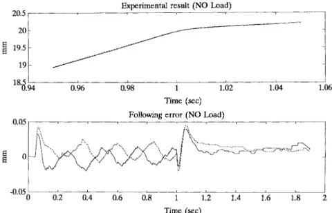
Fig. 5. Experimental results of different feedrate command input under no-load conditions (——: optimal ZPETC; - - - - -: ZPETC,111111111: command).
Fig. 6. Experimental results of sinusoidal command input under no-load conditions (——: optimal ZPETC; - - - - -: ZPETC;111111111: command).
The estimated system is represented with an autoregressive with exogenous input (ARX) mathematical model as
(17) where ; ; given; one-step-delay operator;
, output and input signals, respectively; white Gaussian noise;
, both coprime.
Rewrite (17) as the regressor form
(18)
where
Define the normalized regressor form as
where
The RLS with the forgetting factor is derived as
(20) where
(21) and
(22) Equations (20)–(22) are parameter estimation calculation equa-tions. Equation (22) implies that the forgetting factor for the constant trace of the covariance matrix prevents the covariance matrix from blowing up and the estimations from going to sleep. To guarantee the stability and convergence during the estimation process, interested readers are referred to [20] for a more detailed description.
IV. IMPLEMENTATION ANDEXPERIMENTAL RESULTS
The hardware layout of the dc servo motor tracking control system is shown in Fig. 3. The sampling period is chosen as 1 ms. The PC-486 implements the main control structure which includes generation of control signals, parameter calcu-lation of the feedforward controller, and control of the position
feedback loop. The UT-80 DC servo driver with analog current signal feedback includes a velocity loop, a current loop, and a pulsewidth modulation (PWM) drive. The interface of the PC-486 utilizes a PCL-818 card and an 8255 I/O card to send and receive the control input and position output signals, respectively. The payload W is to simulate the cutting force applied to the X–Y table.
In the present setup, four controllers were adopted to conduct the experiments as follows:
1) is the the proportional gain position controller without ZPETC;
2) ZPETC;
3) optimal ZPETC;
4) adaptive ZPETC is an RLS is applied to the optimal ZPETC.
By system identification [24], the ARX mathematical model for the present velocity servo loop is obtained as (23), shown at the bottom of the page.
The proportional gain position controller which makes the position feedback loop internally stable is chosen as
(24) Thus, the position feedback loop system transfer function can be directly derived as (25), shown at the bottom of the page. The acceptable zeros in here are determined simply to be less than 0.9, and the desired gain bandwidth is selected as (125 Hz). As the order of the DPF is selected as the optimal ZPETC controller is obtained by (14) as
(26) Both the ZPETC and the present optimal ZPETC result in zero phase error response. Moreover, as shown in Fig. 4, the bandwidth of the closed loop with the optimal ZPETC is significantly improved from 186 to 346 Hz. Although the resultant optimal ZPETC is in a high-order model, the present PC-486 is capable of handling the motion system with sampling period of 1 ms.
Experiments under both no-load and loading conditions were conducted with two motion commands as in the fol-lowing.
(23)
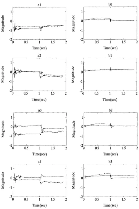
Fig. 7. Parameters estimations when adaptive ZPETC is applied (——: loading; - - - - -: no load).
1) Two-Constant Feedrate Command: The feedrate changes from the first segment at a speed of 1.263 m/min with 20-mm length to the second segment at a speed of 0.3 m/min with 5-mm length.
2) Sinusoidal Command: A sinusoidal command was per-formed with a 6.25-mm amplitude at a speed of 1.9635 m/min for 1.2 s.
For the two-constant feedrate command, as shown in Fig. 5, the tracking error becomes significant when the command is suddenly changed, and the optimal ZPETC results in better responses because of its improved bandwidth, as shown in Fig. 4. For the sinusoidal command, the tracking error for these two controllers is about the same, as shown in Fig. 6. Theoretically, the given sinusoidal command is in a low-frequency range. Under such circumstances, the improvement of the present optimal ZPETC becomes negligible.
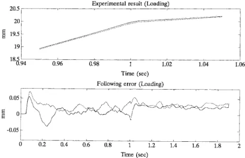
Further, a 30-kg weight was applied to the mechanical position table to induce more serious tracking error. As shown
in Fig. 7, most of the estimated parameters obtained by the RLS algorithm indicate meaningful changes due to the loading effect. The tracking accuracy of the optimal ZPETC and adaptive ZPETC are compared under the loading. Results show that the degraded tracking error of the optimal ZPETC due to the loading is apparently reduced by applying the adaptive ZPETC for both commands, as shown in Figs. 8 and 9, respectively.
V. DISCUSSIONS
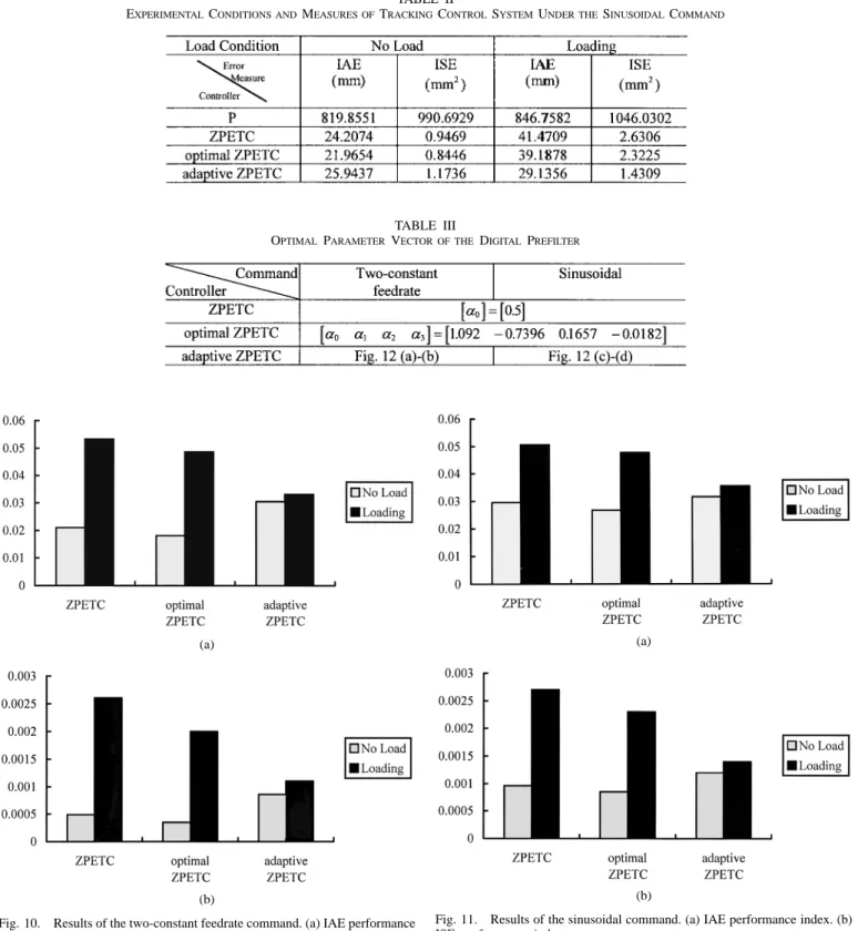
To illustrate the tracking accuracy corresponding to different controllers, experimental results are listed in Tables I and II and their normalized bar charts with respect to the results of the P controller are plotted as shown in Figs. 10 and 11 for the two commands, respectively. Both results show that the optimal ZPETC achieves the least tracking error in both integral absolute-error (IAE) and integral square-error (ISE) indexes when there is no load applied. Compared to the optimal
Fig. 8. Experimental results of different feedrate command input under loading conditions (——: adaptive ZPETC; - - - - -: optimal ZPETC;111111111: command).
Fig. 9. Experimental results of sinusoidal command input under loading conditions (——: adaptive ZPETC; - - - - -: optimal ZPETC;111111111: command). TABLE I
EXPERIMENTALCONDITIONS ANDMEASURES OFTRACKINGCONTROLSYSTEMUNDER THETWO-CONSTANTFEEDRATECOMMAND
ZPETC, the estimation error of the adaptive ZPETC, which is applied to the system without loading, unavoidably results in degraded tracking performance. However, when the external load is applied, the adaptive ZPETC apparently achieves the least tracking error because of its parameter estimation and
adaptive compensation capabilities, as shown in both Figs. 10 and 11.
All provided results indicate that the proposed optimal and adaptive ZPETC design methods have significantly improved the ZPETC in real applications. Experimental results for
TABLE II
EXPERIMENTALCONDITIONS ANDMEASURES OFTRACKINGCONTROLSYSTEMUNDER THESINUSOIDALCOMMAND
TABLE III
OPTIMAL PARAMETER VECTOR OF THEDIGITALPREFILTER
(a)
(b)
Fig. 10. Results of the two-constant feedrate command. (a) IAE performance index. (b) ISE performance index.
all the conventional ZPETC, the optimal ZPETC and the adaptive ZPETC under both no-load and loading conditions are summarized as follows.
1) The commands with sudden changes imply that signals with high-frequency components are included. As listed in Table III, only one parameter is equivalent to 0.5 in the conventional ZPETC, while four parameters are obtained in the optimal ZPETC. Therefore, in the present
(a)
(b)
Fig. 11. Results of the sinusoidal command. (a) IAE performance index. (b) ISE performance index.
optimal ZPETC control design, its bandwidth is higher than that of the conventional ZPETC. Under the two-constant feedrate command, Figs. 5 and 6 show that the difference between the conventional ZPETC and the optimal ZPETC is significant only at the initial stage and the sudden changed velocity. In other words, under the sinusoidal command, the smooth signals, which are in the low-frequency range, lead to negligible improvement
(a) (b)
(c) (d)
Fig. 12. The optimal parameters of the digital prefilter DP FM(z01) when adaptive ZPETC is applied. (a), (b) For two-constant feedrate command. (c), (d) For sinusoidal command (——: loading; - - - - -: no load).
of the present optimal ZPETC, as shown in Figs. 5 and 6. In general, the optimal ZPETC performs better than the conventional ZPETC, as shown in Figs. 10 and 11. 2) In the present adaptive ZPETC with the RLS algorithm, a fourth-order model was used for efficient compu-tations. Note that a more accurate sixth-order model with less modeling errors was used in the conventional ZPETC and the optimal ZPETC. Therefore, under the no-load conditions, the modeling error for the adaptive ZPETC is more significant in the high-frequency range and, thus, its tracking error is even larger than that of the other two ZPETC’s. However, as a 30-kg load is applied, the other two ZPETC’s are sensitive to disturbance, but the adaptive ZPETC still maintains similar motion accuracy, as shown in Figs. 10 and 11. The optimal
parameter vector of the DPF is shown in
Fig. 12. Results indicate that the obtained are changed according to the estimated parameters of the system.
VI. CONCLUSION
To improve tracking accuracy in motion control, various enhanced ZPETC’s have been developed recently. In this paper, by applying the Lagrange method to -norm optimiza-tion, we obtain a concise polynomial DPF for the proposed optimal ZPETC to significantly increase the bandwidth of the magnitude response and maintain the zero phase error for the tracking control system. Moreover, due to the efficient computations of the proposed DPF, we further employ the RLS algorithm to construct the adaptive ZPETC which is more capable than the others when external loads are applied. Exper-imental results on a dc servo table with different controllers
indicate that, when there is no loading, the present optimal ZPETC achieves the best tracking performance. Moreover, the adaptive ZPETC achieves the most satisfactory results when an external load is applied.
The present optimal and adaptive ZPETC design approaches provide efficient algorithms and achieve real-time implemen-tation in practice. All experimental results have proven the improved tracking accuracy and feasibility of the proposed motion control design.
APPENDIX
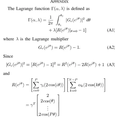
The Lagrange function is defined as
(A1) where is the Lagrange multiplier
(A2) Since (A3) and .. .
.. . ... . .. ... (A4) where .. . ... .. . Therefore, (A5) and .. . (A6) where
By substituting (A5) and (A6) into (A1), we obtain (A7) where
Let
(A8) (A9) By multiplying matrix to both sides of (A8), then
(A10) From (A9),
(A11) By substituting (A11) into (A10), we obtain the Lagrange multiplier as
(A12) Again, by substituting (A12) into (A8), the optimal parameters
of the DPF is obtained as
(A13) where definitions are given at the bottom of the page.
..
. ... . .. ...
..
REFERENCES
[1] M. Tomizuka, “Zero phase error tracking algorithm for digital control,”
ASME J. Dynam. Syst., Meas., Contr., vol. 109, pp. 65–68, Mar. 1987.
[2] T. C. Tsao and M. Tomizuka, “Robust adaptive and repetitive digital tracking control and application to a hydraulic servo for noncircular machining,” ASME J. Dynam. Syst., Meas., Contr., vol. 116, pp. 24–32, Mar. 1994.
[3] , “Adaptive and repetitive digital control algorithms for noncir-cular machining,” in Proc. 1988 American Control Conf., 1988, pp. 115–120.
[4] , “Adaptive zero phase error tracking algorithm for digital con-trol,” ASME J. Dynam. Syst., Meas., Contr., vol. 109, pp. 349–354, Dec. 1987.
[5] H. S. Lee and M. Tomizuka, “Robust motion controller design for high-accuracy positioning systems,” IEEE Trans. Ind. Electron., vol. 43, pp. 48–55, Feb. 1996.
[6] B. Yao, M. Al-Majed, and M. Tomizuka, “High-performance robust motion control of machine tools: An adaptive robust control approach and comparative experiments,” IEEE/ASME Trans. Mechatron., vol. 2, pp. 63–76, June 1997.
[7] Y. Funahashi and M. Yamada, “Zero phase error tracking controllers with optimal gain characteristics,” ASME J. Dynam. Syst., Meas., Contr., vol. 115, pp. 311–318, Sept. 1993.
[8] D. Torfs and J. De Schutter, “Optimal feedforward prefilter with frequency domain specification for nonminimum phase systems,” ASME
J. Dynam. Syst., Meas., Contr., vol. 118, pp. 791–795, Dec. 1996.
[9] J. Z. Xia and C. H. Menq, “Precision tracking control of nonminimun phase systems with zero phase error,” Int. J. Contr., vol. 61, no. 4, pp. 791–807, 1995.
[10] M. Yamada, Y. Funahashi, and S. Fujiwara, “Zero phase error tracking system with arbitrarily specified gain characteristics,” ASME J. Dynam.
Syst., Meas., Contr., vol. 119, pp. 260–264, June 1997.
[11] L. Guo and M. Tomizuka, “High-speed and high-precision motion control with an optimal hybrid feedforward controller,” IEEE/ASME
Trans. Mechatron., vol. 2, pp. 110–122, June 1997.
[12] B. Haack and M. Tomizuka, “The effect of adding zeros to feedforward controllers,” ASME J. Dynam. Syst., Meas., Contr., vol. 113, pp. 6–10, Mar. 1991.
[13] C. H. Menq and J. J. Chen, “Precision tracking control of discrete time nonminimun phase systems,” ASME J. Dynam. Syst., Meas., Contr., vol. 115, pp. 238–245, June 1993.
[14] D. Torfs, J. De Schutter, and J. Swevers, “Extended bandwidth zero phase error tracking control of nonminimum phase systems,” ASME J.
Dynam. Syst., Meas., Contr., vol. 114, pp. 347–351, Sept. 1992.
[15] D. Torfs, J. Swevers, and J. De Schutter, “Quasiperfect tracking control of nonminimum phase systems,” in Proc. 30th Conf. Decision and
Control, 1991, pp. 241–244.
[16] E. D. Tung, M. Tomizuka, and Y. Urushisaki, “High-speed end milling using feedforward control architecture,” ASME J. Manuf. Sci. Eng., vol. 118, pp. 178–187, May 1996.
[17] M. Weck and G. Ye, “Sharp corner tracking using the IKF control strategy,” Ann. CIRP, vol. 39, no. 1, pp. 437–441, 1990.
[18] E. D. Tung and M. Tomizuka, “Feedforward tracking controller design
based on identification of low frequency dynamics,” ASME J. Dynam.
Syst., Meas., Contr., vol. 115, pp. 348–356, Sept. 1993.
[19] , “Application of frequency-weighted least squares system identi-fication to feedforward tracking controller design,” in Proc. Japan/USA
Symp. Flexible Automation, 1992, vol. 1, pp. 503–510.
[20] R. Lozano-Leal, “Convergence analysis of recursive identification al-gorithm with forgetting factor,” Automatica, vol. 19, no. 1, pp. 95–97, 1983.
[21] A. V. Oppenheim and R. W. Schafer, Discrete Time Signal Processing. Englewood Cliffs, NJ: Prentice-Hall, 1989.
[22] F. B. Yeh, Post Modern Control Theory and Design. Taipei, Taiwan, R.O.C.: Eurasia, 1990.
[23] G. C. Goodwin and K. S. Sin, Adaptive Filtering Prediction and Control. Englewood Cliffs, NJ: Prentice-Hall, 1984.
[24] T. S¨oderstr¨om and P. Stoica, System Identification. Englewood Cliffs, NJ: Prentice-Hall, 1989.
[25] O. P. Malik, G. S. Hope, and S. J. Cheng, “Some issue on the practical use of recursive least squares identification in self tuning control,” Int.
J. Contr., vol. 53, no. 5, pp. 1021–1033, 1991.
[26] N. R. Sripada and D. G. Fisher, “Improved least squares identification,”
Int. J. Contr., vol. 46, no. 6, pp. 1889–1913, 1987.
[27] P. E. Wellstead and J. M. Edmunds, “Least-squares identification of closed-loop systems,” Int. J. Contr., vol. 21, no. 4, pp. 689–699, 1975.
Syh-Shiuh Yeh received the B.S. degree in
mechan-ical engineering in 1994 and the M.S. degree in control engineering in 1996 from National Chiao Tung University, Hsinchu, Taiwan, R.O.C., where he is currently working toward the Ph.D. degree in the Institute of Electrical and Control Engineering. His research interests include motion system and controller design.
Pau-Lo Hsu (M’91) received the B.S. degree from
National Cheng Kung University, Tainan, Taiwan, R.O.C., the M.S. degree from the University of Delaware, Newark, and the Ph.D. degree from the University of Wisconsin, Madison, in 1978, 1984, and 1987, respectively, all in mechanical engineering.
Following two years of military service in King-Men, he was with San-Yang (Honda) Industry during 1980–1981 and Sandvik (Taiwan) during 1981–1982. In 1988, he joined the Department of Electrical and Control Engineering, National Chiao Tung University, Hsinchu, Taiwan, R.O.C., as an Associate Professor. He became a Professor in 1995. Since 1998, he has been the Chairman of the department. His research interests include mechatronics, motion control, and fault diagnostic systems.