A Retrodirective Microstrip Antenna Array
Shyh-Jong Chung,
Member, IEEE, and Kai Chang,
Fellow, IEEEAbstract—A Van Atta retrodirective reflector was designed and developed, using an aperture-coupled microstrip antenna array. This reflector possesses the advantage of reflecting high fields to the source point over a wide range of incidence angles and, owing to the low cost and comformability of the structure, is suitable for applications in intelligent vehicle highway systems (IVHS). An approximate theory associated with the reradiation and scattering principles of the reflector is presented for the purpose of understanding and designing the reflector. The utility of the retrodirective reflector was demonstrated by comparison with a plate reflector and a microstrip antenna array without a feed structure. Finally, a reflector with switches in the middle of the microstrip feed lines was investigated for possible applications in communications and remote identification.
Index Terms— Microstrip antenna arrays, microstrip patch antenna, retrodirective antenna.
I. INTRODUCTION
D
UE to the swift decline of military spending and rapid advancement of component technology, microwave, and millimeter-wave systems have moved from military applica-tions to commercial ones over the past few years [1]–[6]. Two interesting applications in the commercial area are automotive collision avoidance and road traffic management, both playing important roles in future intelligent vehicle highway systems (IVHS). The former provides the services of warning the driver of potential hazards in his path, including vehicles and roadside obstacles. The latter contains several aspects of road transport informatics and may be accomplished by the communications between vehicles and roadside beacons [1].For automotive collision avoidance, many researchers have focused on the developments of vehicle radars, including forward-looking, backward-looking, and sideward-looking radars [2], [3]. These radars emit modulated continuous waves (CW) or pulsed waves and receive echoes from other vehicles or roadside obstacles (man-made traffic structures, topographic structures, etc.). Information such as distance and speed, can then be read from the echoes to produce warning signals. However, the echo from a vehicle relies on scattering from the vehicle body and is narrow beamed. Only near normal directions to the body surface can a high reflected field be obtained. The higher the frequency used, the narrower the reflected beam is (for a given antenna size). Therefore, outside the return signal beamwidth the radar can not receive any response. One possible solution to this limitation of the
Manuscript received August 5, 1996; revised July 8, 1998.
S.-J. Chung is with the Department of Communication Engineering, Chiao Tung University, Hsinchu, Taiwan, R.O.C.
K. Chang is with the Department of Electrical Engineering, Texas A&M University, College Station, TX 77843 USA.
Publisher Item Identifier S 0018-926X(98)09685-9.
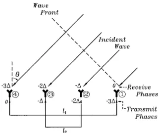
Fig. 1. A four-element Van Atta retrodirective array.
radar is to increase the scattering beamwidth of vehicles, which can be achieved by placing retrodirective reflectors on the vehicle surfaces and road obstacles.
In this paper, we describe a Van Atta retrodirective reflector using a microstrip antenna array. The concept of this reflector was first proposed by L. C. Van Atta [7] and it possesses the advantage that the field reradiated by the reflector has a maximum in the direction of the incident plane wave. Fig. 1 illustrates a reflector composed of four antennas. Antennas 1 and 4 are paired by a transmission line of length , and antennas 2 and 3 are by a line of length . A plane wave is incident upon the array at an angle , which introduces a receiving phase lag of between the adjacent antennas. is the free-space propagation constant and is the distance between antennas.) The signals received by antenna 1 and antenna 2 are fed through the transmission lines to antenna 4 and antenna 3, respectively, and vice versa. If the difference between and equals a multiple of the wavelength in the transmission lines, a feeding phase excess of exists between the antennas, thus forcing the antenna array to radiate toward the direction from which the incident wave comes.
After the report of L. C. Van Atta, many investigations of this type of reflector were done using dipole antennas or horn antennas [8]–[11]. Instead of a pure passive configuration, some also added bidirectional amplifiers or mixers in the transmission lines to enhance and/or modulate the echoes [12]. The applications of the Van Atta reflector have been proposed in satellite communication [13] and in enhancing the radar cross sections of ships and airplanes [14].
The proposed microstrip antenna type of Van Atta reflec-tor has the advantages of easy design, low cost, and great 0018–926X/98$10.00 1998 IEEE
(a)
(b) (c)
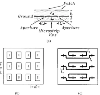
Fig. 2. (a) The (partial) side view. (b) The top view. (c) The bottom view of a retrodirective aperture-coupled microstrip antenna array. The apertures (dashed lines) are located on the ground plane between (b) the antenna substrate and (c) the circuit substrate.
conformability to a given surface shape and is thus a good candidate for use in the abovementioned vehicle collision avoidance radar and obstacle warning systems. Another ap-plication of this array reflector is in road traffic management, where it can be furnished in a vehicle as an on-board unit [4] to communicate with roadside beacons. To do this, switches or amplifiers might be incorporated in the array reflector. By controlling the on–off states of such switches or amplifiers, the array can reflect the amplitude modulated signals to the beacons. Owing to the retrodirective effect of this on-board unit, the vehicle can have a large communication angle and range with beacons [4]. These semi-active (switches) or active (amplifiers) retrodirective reflectors can also be used in remote identification of persons or vehicles [6]. By adding identification binary codes to control the switches or amplifiers, the reflectors can return coded responses to the interrogators.
II. DESIGN OF MICROSTRIP ANTENNA
Fig. 2 shows the new retrodirective reflector. A two-layer configuration was used in this design [Fig. 2(a)]. Three iden-tical E-plane subarrays were made to enhance the echo of the reflector. Each linear subarray contains two pairs (four elements) of aperture-coupled microstrip antennas [Fig. 2(b)] fed by two equal-length microstrip lines on the reverse side of the ground plane [Fig. 2(c)]. To reduce the influence of the mutual couplings between antennas, the dis-tances between subarrays and between subarray elements are set equal to 21 and 18 mm, respectively, which are 0.7 and 0.6 for a frequency of 10 GHz. The thickness and the relative dielectric constant of the circuit substrate are 0.508 mm and 2.2, respectively, resulting in a width of 1.6 mm for a 50- microstrip feed line. The antenna substrate has a thickness of 0.787 mm and a relative dielectric constant of 2.3. To reduce the interference caused by the scattering
from the ground plane, the whole size of the reflector is kept as small as possible and is measured to be 76 68 mm .
The antenna and the feed structure were designed using a commercial program, PCAAD [15]. The widths of the microstrip antenna and the microstrip feed line were 12 mm and 1.6 mm, respectively. The other parameters were then varied to produce a 50- input impedance (seen by the feed line) at a frequency of 10 GHz, so that maximum power can be received by the microstrip line from one antenna and be reradiated from the other antenna of the same pair. The computed length of the antenna, size of the aperture, and length of the microstrip matching stub line are 8.73 mm, 4 1 mm , and 5 mm, respectively. To verify the aperture-coupled antenna design, a separate single-element aperture-coupled microstrip antenna was made and measured. A return loss of as low as 19 dB at the center frequency of 10.025 GHz was obtained, which ensured the validity of the design.
Although putting the feed lines on the same plane as the antennas can reduce complexity, the aperture-coupled configuration was chosen due to two considerations. First, the microstrip lines in the coplanar design may produce extra radiation, deteriorating the performance of the reflector. Although not shown in this paper, this has been verified for the configuration with antennas directly fed by high-impedance lines (170 ) and for that with antennas fed by medium impedance lines (85 ) through quarter-wavelength transformers (120 ). (Microstrip lines of 50 are too wide to be incorporated on the antenna plane.) Second, since no an-tenna appears in the circuit substrate for the aperture-coupled structure, there is more space and, thus, more flexibility for routing of the microstrip lines. Also, it is easier to add other solid-state circuits such as switches or amplifiers (if needed) in the aperture-coupled structure.
III. THEORY OF RETRODIRECTIVE MICROSTRIP-ANTENNA REFLECTOR
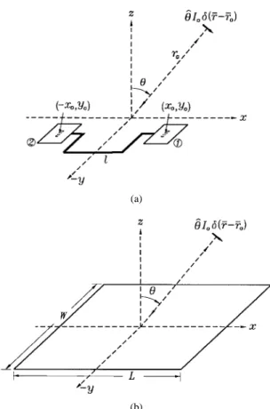
For a better understanding of the proposed retrodirective reflector, an approximate theory was developed to analyze the structure. The field returning to the source point of the plane wave is primarily composed of three parts: the reradiated field, the scattered field from the terminated patch antennas [16], and the scattered field from the partially covered ground plane. When a wave is incident upon an array, some of the power is captured by the antennas and then reradiated from corresponding antennas of the same pairs [Fig. 3(a)], causing a reradiated field to the source point. In addition, some of the power is scattered by the microstrip patches and by the partially covered ground plane, which contributes to the two scattered field components. The scattered field from the patch antennas comes from the patch currents induced by the incident wave. For simplicity, these currents are approximated as physical optics (PO) currents [17]. The radiation of the edge currents induced on the patches is ignored. Thus, since the antenna substrate is thin enough (as compared to the wavelength) to be ignored, a flat metal plate of the same size ( mm ) as the ground plane is used to compute the total scattered field [Fig. 3(b)]. In the following analysis,
(a)
(b)
Fig. 3. (a) A pair of aperture-coupled microstrip antennas for analyzing the reradiated fields. (b) A flat metal plate used to calculate the scattered fields.
the feed lines and the antennas are assumed to be matched so that no reflection field is excited when a guided field is fed from a feed line to an antenna. The mutual couplings between antennas and possibly between microstrip lines are neglected. Also, the diffraction of the reradiated field by the ground plane edges is ignored.
Fig. 3(a) shows a pair of the microstrip antennas illumi-nated by an incident field coming from a point source at . The antennas are linked by a microstrip line of length (from feed point to feed point). Some of the incident field is absorbed by antenna 1, leading to a dominant microstrip mode propagating through the microstrip feed line from antenna 1 to antenna 2. Let be the complex coefficient of this mode at the feed point of antenna 1 and be the corresponding tangential modal field. To find , the following reciprocity theorem [18] is used:
(1) where is the tangential field at the cross section of the microstrip line passing through the point , due to the presence of the point source . is a hypothetical surface current distributed at the surface , which produces a radiation field by way of antenna 1. Letting and expanding with the modal fields
of the microstrip line
(2)
(1) becomes
(3) in which the orthonormality property of the modal fields has been incorporated.
The radiation field of antenna 1 due to the presence of the surface current can be obtained from the cavity-mode theory of the microstrip antenna [19]
(4) with
(5) where is the effective length of the microstrip antenna, , with being the physical antenna length and the thickness of the antenna substrate. is a feed (complex) factor depending on the configuration of the antenna feed.
The microstrip dominant mode excited at antenna 1 propa-gates through the feed line to antenna 2, causing a reradiation field to the source point. The field of the microstrip mode at the feed point of antenna 2 is , which, by the equivalent current principle [18], can be viewed as excited by a surface current
at the feed point. ( and , with
and being the wavelength and the effective relative dielectric constant of the microstrip line, the intrinsic impedance of the free-space.) Therefore
(6) where has the same form as (4) but with substituted by . Note that since antenna 2 has an opposite polarization to antenna 1, a minus sign is added in (6). Casting (3) and (4) into (6), one obtains
(7) By following the above procedure, it is easy to find that , i.e., the reradiated field from antenna 1, is exactly equal to . Thus, the total reradiated field from all the antenna pairs is
(8) where is the number of antenna pairs that equals six in the present design. Note that the phase of depends on the length of the microstrip feed lines and also that is proportional to the square of the radiation pattern of a single-array element.
To compute the scattered field, PO and the method of equivalent currents (MEC) are used [17]. By the PO method,
the backscattering field from the flat plate to the source point [Fig. 3(b)] is
(9) This expression gives a very accurate result when ,
with being the angle where the first
null of appears. As is increased larger than , the field predicted by PO becomes underestimated. A more reliable expression can be obtained by using the MEC, which is an extension of the geometrical theory of diffraction (GTD) for applications in three-dimensional problems [17]
(10) The total field returning from the array reflector to the source point is
(11) where
for
for . (12)
IV. CALCULATION AND MEASUREMENT RESULTS As can be seen from (11) and (8) due to the interference between the reradiated field and the scattered field, the pattern of the total reflected field will change when the length of the microstrip lines is varied. To verify this, three array reflectors with the same design parameters but different ’s, were made and measured to compare with theoretical results. The lengths are 64, 62, and 65 mm, which, respectively, correspond to 2.948 , 2.856 , and 2.994 at the frequency of 10.025 GHz. Since the currents on the patches are approximated as PO currents in the theory, there may be a difference between the radiation field level from the actual currents and that from these PO currents. Thus, both the amplitude and the phase of the feed factor in (5) are adjusted to make up for this difference so that a best match between the theoretical and measured patterns for the reflector of mm is met. Once is decided from this structure, it is also used to compute the patterns for reflectors of mm and mm. Before discussing the following results, it should be noticed that the received power in the calculated and the measured patterns shown below are normalized to, respectively, the calculated and the measured scattered power of the flat plate at the specular direction .
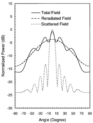
Fig. 4 depicts the theoretical results for the total, reradiated, and scattered fields of the reflector with mm. It is seen that the reradiated field is a slow-varying function of the angle , which is the principal contribution to the retrodirectivity of the array reflector. On the contrary, both the amplitude and the phase of the scattered field change quickly with the angle,
Fig. 4. Theoretical returning-field patterns for a retrodirective reflector of
l = 64 mm.
leading to an oscillatory behavior of the total returning field. Since the scattered fields at angles away from the normal of the reflector are much less than the reradiated fields, they can only cause small ripples at these angles. But when the incidence angle is near the reflector normal direction, the scattered field becomes comparable to, if not larger than, the reradiated field. Therefore, different designs of the length of the feed lines, which result in different phases of the reradiated field, may lead to quite distinct total-field patterns near this direction. This will be obvious in the next few illustrations.
Figs. 5–7 show the measured retroreflected-field patterns
of the reflectors with mm, mm, and mm,
respectively. The calculated patterns are also included for comparison. It is seen from Fig. 5 that a smooth pattern is achieved for the design of mm. The variation of the reflected field stays within 8 dB in a very wide range of angles
(about from to ). As predicted by the
theory, when the length of the feed line is reduced (Fig. 6) or increased (Fig. 7), the measured fields near the reflector normal decrease or increase, respectively. One also observes
that at the neighborhoods of ,
(where mm is the subarray interelement distance,) the measured field levels are larger than the calculated field levels for all the three reflectors. At the angles of , the round-trip path difference between the adjacent antennas equals a free-space wavelength and, thus, leads to constructive interference fields scattered from the microstrip antennas. (These scattered fields may be caused by the edge currents induced on the patches and/or by the self-reradiations of the antennas due to the mismatch at the feed points.) Since these coherent fields are not considered in the analysis, the calculated results are thus smaller than the measured ones. Nevertheless,
Fig. 5. Comparison between the measured and the calculated returning-field patterns for a retrodirective reflector ofl = 64 mm.
Fig. 6. Comparison between the measured and the calculated returning-field patterns for a retrodirective reflector ofl = 62 mm.
an overview of Figs. 5–7 shows that the present theory is useful in explaining the scattering mechanism of the reflector and in predicting the variation trend of the field patterns due to the change of the feed-line length.
Fig. 7. Comparison between the measured and the calculated returning-field patterns for a retrodirective reflector ofl = 65 mm.
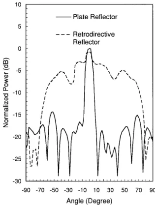
Fig. 8. Measured returning-field patterns for a metal-plate reflector and a retrodirective reflector.
Since the reflector of mm has a better performance than the others, it will be used in the following to demon-strate the advantages of the proposed array reflector. Fig. 8 compares the measured patterns of the reflected fields for
Fig. 9. Measured returning-field patterns for a microstrip antenna array (same elements as the retrodirective reflector but without feed structures) and a retrodirective reflector.
the retrodirective reflector and a plate reflector of the same size. It is seen that the plate reflector only contributes high returning fields in the range between . Outside this range, its fields are strongly oscillatory and are much less than those of the retrodirective reflector. Fig. 9 illustrates the backscattering field patterns for a microstrip antenna array and the retrodirective reflector. The geometry of the antenna array is similar to that of the reflector, but without any feed structures. There are three high lobes in the curve of the antenna array, one near the normal direction and the others
around . The lobe near is caused by
the specular scattering of the structure, while those around are the effects of the self-reradiations and the radiation of edge currents in the array. In between these lobes, the returning fields are much weaker (if not falling to nulls) as compared to those of the retrodirective reflector.
As mentioned earlier, microwave/millimeter-wave switches can be incorporated in the present reflector for the use in com-munications and remote identifications. One possible design is to place the switches in the middle of the microstrip feed lines. When the switches are in the on-state, guided waves can go through the microstrip lines, leading to high returning fields in a wide range of incidence angles, as has been demonstrated above. But as the switches are in the off-state, the lines are blocked and the waves are reflected back to the incoming antennas, thus destroying the retrodirectivity of the reflector. In this study, gaps with lengths of 2 mm are made in the microstrip lines to simulate a reflector in the off state. The measured pattern of this reflector is shown in Fig. 10, together with that of the on-state reflector for comparison. Owing to a
Fig. 10. Measured returning-field patterns for an off-state and an on-state switching retrodirective reflector.
similar reason as for the microstrip antenna array, the off-state reflector has three major lobes. (The distinctions between the patterns of the off-state reflector and the microstrip antenna array are due to the extra microstrip stub attached to each antenna in the off-state reflector, which results in a difference phase of the self-reradiation field.) Only in between these lobes can a larger difference between the off-state and on-state fields
exist. In the ranges of to and to ,
the reflected power of the off-state reflector is about 6 dB (in average) lower than that of the on-state reflector.
Fig. 11 presents the measured H-plane pattern for the re-flected fields of the retrodirective reflector ( mm). Since our structure is only designed for use in the E-plane directions, the H-plane beamwidth is quite narrow as expected. The 3-dB and 10-dB beamwidths are 11 and 19 , respectively.
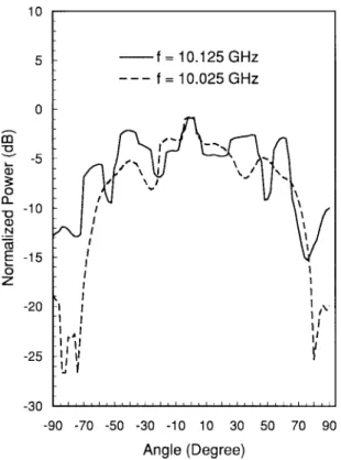
Figs. 12 and 13 show the reflected-field patterns for the reflector of mm at the frequencies of 10.125 and 9.925 GHz, respectively. The return losses at the feed points for these frequencies are both equal to 13 dB, which are 6 dB more than that for the center frequency (10.025 GHz). This return loss results in higher self-reradiation fields due to the reflections at both the feed points of the antennas in the same pair, which, in turn, interfere with the array reradiation field. The patterns with many ripples like those shown in the figures are thus produced. Nevertheless, since the losses are still small for these two frequencies, the ripples do not give large changes on the levels of the patterns.
V. CONCLUSIONS
In this paper, we have designed and demonstrated the performance of a retrodirective reflector using the
aperture-Fig. 11. H-plane returning-field pattern for a retrodirective reflector of
l = 64 mm.
Fig. 12. Measured returning-field patterns for a retrodirective reflector of
l = 64 mm at the frequencies of 10.125 and 10.025 GHz.
coupled microstrip antenna array. An approximate theory considering the reradiation and the scattering effects of this array reflector has been introduced, which showed a good agreement with the measurement. According to this theory, the
Fig. 13. Measured returning-field patterns for a retrodirective reflector of
l = 64 mm at the frequencies of 9.925 and 10.025 GHz.
reradiated fields from the antennas are the primary contribution to the retrodirectivity property of the reflector. The lengths of the microstrip feed lines should be suitably designed so that a well-interfered pattern by the reradiated and scattered fields can be achieved.
The new retrodirective reflector has been compared with a flat-plate reflector of the same size. The returning-field pattern of the former possesses a beamwidth larger than 120 , while that of the latter is only 10 . A comparison has also been made between the present reflector and a microstrip antenna array without a feed structure. Although due to the edge diffraction and self-reradiation effects the microstrip antenna array gives high returning fields at angles away from the specular direction, the fields at other angles are much weaker as compared to the retroreflector. A switching retrodirective reflector together with the field patterns at frequencies off from the designed one was also discussed.
To practically apply the proposed retrodirective configura-tion in the applicaconfigura-tions menconfigura-tioned in the introducconfigura-tion, a larger array reflector may be needed so that stronger echoes can be received. A reflector that not only reradiates the fields in the E-plane but also in the H-plane is also needed. To realize these reflectors, a more complicated routing approach for the feed lines should be considered in the future.
ACKNOWLEDGMENT
The authors would like to thank M.-Y. Li and L. Fan for their assistance and suggestions in the measurement. They would also like to thank the reviewers for their careful review and useful suggestions about this paper.
REFERENCES
[1] H. H. Meinel, “Commercial applications of millimeterwaves: History, present status, and future trends,” IEEE Trans. Microwave Theory Tech., vol. 43, pp. 1639–1653, July 1995.
[2] D. A. Williams, “Millimeter wave radars for automotive applications,” in IEEE MTT-S Int. Microwave Symp. Dig., Albuquerque, NM, June 1992, vol. 2, pp. 721–724.
[3] K. W. Chang, H. Wang, G. Shreve, J. G. Harrison, M. Core, A. Paxton, M. Yu, C. H. Chen, and G. S. Dow, “Forward-looking automotive radar using a W-band single-chip transceiver,” IEEE Trans. Microwave Theory
Tech., vol. 43, pp. 1659–1668, July 1995.
[4] F. Dobias and W. Grabow, “Adaptive array antennas for 5.8 GHz vehicle to roadside communication,” in IEEE 44th Veh. Tech. Conf., Stockholm, Sweden, 1994, vol. 3, pp. 1512–1516.
[5] H.-J. Schrewe and E. M. GmbH, “An adaptive antenna array for mobile reception of DBS-satellites,” in IEEE 44th Veh. Tech. Conf., Stockholm, Sweden, 1994, vol. 3, pp. 1494–1497.
[6] C. W. Pobanz and T. Itoh, “A microwave noncontact identification transponder using subharmonic interrogation,” IEEE Trans. Microwave
Theory Tech., vol. 43, pp. 1673–1679, July 1995.
[7] L. C. Van Atta, “Electromagnetic reflector,” U.S. Patent 2 908 002, Serial no. 514 040, Oct. 1959.
[8] J. Appel-Hansen, “A Van Atta reflector consisting of half-wave dipoles,”
IEEE Trans. Antennas Propagat., vol. AP-14, pp. 694–700, Nov. 1966.
[9] K. Walther, “Model experiments with acoustic Van Atta reflectors,” J.
Acoust. Soc. Amer., vol. 34, pp. 665–674, May 1962.
[10] T. Larsen, “Reflector arrays,” IEEE Trans. Antennas Propagat., vol. AP-14, pp. 689–693, Nov. 1966.
[11] E. D. Nielsen, “Square Van Atta reflector with conducting mounting plane,” IEEE Trans. Antennas Propagat., vol. AP-18, pp. 48–54, Jan. 1970.
[12] S. N. Andre and D. J. Leonard, “An active retrodirective array for satellite communications,” IEEE Trans. Antennas Propagat., vol. AP-12, pp. 181–186, Mar. 1964.
[13] E. L. Gruenberg and C. M. Johnson, “Satellite communications relay system using a retrodirective space antenna,” IEEE Trans. Antennas
Propagat., vol. AP-12, pp. 215–223, Mar. 1964.
[14] D. E. N. Davies, “Some properties of Van Atta arrays and the use of 2-way amplification in the delay paths,” Proc. Inst. Elect. Eng., vol. 110, pp. 507–512, Mar. 1963.
[15] PCAAD (personal computer aided antenna design), developed by D. M. Pozar, marketed by Antenna Design Assoc., Inc., Leverett, MS. [16] D. M. Pozar, “Radiation and scattering from a microstrip patch on a
uniaxial substrate,” IEEE Trans. Antennas Propagat., vol. AP-35, pp. 613–621, June 1987.
[17] W. L. Stutzman and G. A. Thiele, Antenna Theory and Design. New York: Wiley, 1981.
[18] R. F. Harrington, Time-Harmonic Electromagnetic Fields. New York: McGraw-Hill, 1961.
[19] K. F. Lee and J. S. Dahele, “Characteristics of microstrip patch antennas and some methods of improving frequency agility and bandwidth,” in
Handbook of Microstrip Antennas, J. R. James and P. S. Hall, Ed.
London, U.K.: Peter Peregrinus, 1989, ch. 3.
Shyh-Jong Chung (M’92) was born in Taipei, Taiwan, R.O.C. He received the B.S.E.E. degree in 1984 and the Ph.D. degree in 1988, both from the National Taiwan University, Taipei, Taiwan, R.O.C.
Since 1988, he has been with the Department of Communication Engineering, National Chiao Tung University, Hsinchu, Taiwan, R.O.C., where he is currently a Professor. From 1989 to 1991 he did his duty to serve in the Taiwan Army as a Second Lieu-tenant, where he was in charge of the maintenance of communication equipment. From September 1995 to August 1996 he was a Visiting Scholar in the Department of Electrical Engineering, Texas A&M University, College Station, TX. His areas of interest include propagation and scattering of transmission lines, packaging effects of microwave circuits, numerical techniques in electromagnetics, and the designs and applications of active or passive planar antennas.
Kai Chang (S’75–M’76–SM’85–F’91) received the B.S.E.E. degree from the National Taiwan Univer-sity, Taipei, Taiwan, the M.S. degree from the State University of New York at Stony Brook, and the Ph.D. degree from the University of Michigan, Ann Arbor, in 1970, 1972, and 1976, respectively.
From 1972 to 1976, he worked for the Microwave Solid-State Circuits Group, Cooley Electronics Lab-oratory of the University of Michigan as a Research Assistant. From 1976 to 1978 he was employed by Shared Applications, Inc., Ann Arbor, MI, where he worked in computer simulation of microwave circuits and microwave tubes. From 1978 to 1981 he worked for the Electron Dynamics Division, Hughes Aircraft Company, Torrance, CA, where he was involved in the research and development of millimeter-wave solid-state devices and circuits, power combiners, oscillators, and transmitters. From 1981 to 1985 he worked for TRW Electronics and Defense, Redondo Beach, CA, as a Section Head, developing state-of-the-art millimeter-wave integrated circuits and subsys-tems including mixers, voltage controlled oscillators (VCO’s), transmitters, amplifiers, modulators, upconverters, switches, multipliers, receivers, and transceivers. He joined the Electrical Engineering Department of Texas A&M University in August 1985 as an Associate Professor and was promoted to a Professor in 1988. In January 1990, he was appointed E-Systems Endowed Professor of Electrical Engineering. He authored and coauthored several books, including Microwave Solid-State Circuits and Applications (New York: Wiley, 1994), Microwave Ring Circuits and Antennas (New York: Wiley, 1996), and Integrated Active Antennas and Spatial Power Combining (New York: Wiley, 1996). He served as the editor of the four-volume Handbook
of Microwave and Optical Components (New York: Wiley, 1989, 1990). He
is the editor of the Microwave and Optical Technology Letters and the Wiley book series in microwave and optical engineering. He has published more than 300 technical papers and several book chapters in the areas of microwave and millimeter-wave devices, circuits, and antennas. His current interests are in microwave and millimeter-wave devices and circuits, microwave integrated circuits, integrated antennas, wide-band and active antennas, phased arrays, microwave power transmission, and microwave optical interactions.
Dr. Chang received the Special Achievement Award from TRW in 1984, the Halliburton Professor Award in 1988, the Distinguished Teaching Award in 1989, the Distinguished Research Award in 1992, and the TEES Fellow Award in 1996 from Texas A&M University.