ISCAS 2000
-
IEEE International Symposium on Circuits and Systems, May 28-31, 2000, Geneva, SwitzerlandA New
VLSI
Architecture without Global Broadcast for 2-D Digital Filters
Lan-Da Van, Cbih-Chun Tang, Shing Tenqcben
*,
and Wu-Sbiung Feng**Lab 353, Department of Electrical Engineering, National Taiwan University, Taipei, Taiwan, R.O.C. *Chunghwa Telecom Telecommunication Labs., 12, Lane 551, Sec. 5 ,
Min-Tsu Rd., Yang-Mei Zien, Tao-Yuan County, Taiwan 326, R.O.C.
**Department of Electronics Engineering, Chang Gung University, Taoyuan, Taiwan, R.O.C. E-mail: 686039 @
-
C- and -chttl.can&ABSTRACT
In this paper, we propose the new two-dimensional (2-D) systolic-array structures of IIWFIR digital filters without global broadcast by the different derivation and another systolic transformation. For more practical considerations, we further provide a detailed block diagram of a 2-D FIR filter using recently proposed multiplier to reduce the roundoff quantization error in the logic-gate level. These proposed systolic structures amenable to VLSI implementation permit the 2-D input sequence to be scanned in row-wise mode and locally broadcast one value each clock per delay element.
1. Introduction
2-D IIWFIR digital filters have been widely applied to imagehide0 processing applications such as image enhancement and noise reduction. The architectures of 2-D IIWFIR digital filters are mainly derived from either the discrete-time difference equation or transfer function [ 1-31. However, we can obviously find that the input and output signals globally broadcast in these structures [l-31. This is our motivation to improve the structures to be more suitable to VLSI design. In this paper, we propose the improved 2-D systolic structures by the different derivation of the transfer function and first by using the different systolic transformation. The paper is organized as follows. The new systolic architectures for 2-D digital filters are presented in Section 2. In Section 3, comparison results are tabulated in terms of whether the structures eliminate the global broadcast, the critical cycle period, the number of multipliers and delay elements. In the logic-gate level, the block diagram of an FIR digital filter consisting of a lower-error fixed-width multiplier [4] is depicted in Section 4. Thus, the lower quantization error expression due to the finite precision multiplication in digital filters can be addressed in Section 5. At last, the concise statements conclude this paper.
0 This work was supported by National Science Council under NSC: 88-2216-E-002-018.
2. Systolic Architectures without Global Broadcast
A 2-D IIR filter has the following transfer function
i=O j=O
where boo = 0 , aii and b, are the coefficients of the IIR filter, and
N ,
xN,
is the order of the IIR digital filter. We deduce the structure under the assumption ofN , =
N,
=N
= 2 , and then we pay attention to derive 2-D IIR filter structure. For the sake of reducing the operation time, we first apply another systolic transformation as shown in Fig. I(a), which is different from Fig. l(b), to replace the cell as shown in Fig. l(c). Using this systolic transformation as well as tree structure for addition, we can obtain less critical-cycle digital filter in feedback path than [3]. Next, it is commented that there exists the problem of input and output global broadcast of the above temporary filter structure using this systolic transformation and of the previous proposals. Since the global broadcast results in critical path in [l] and another critical path in [3]and this temporary filter structure, we take the different reordering of delay elements and summations of the transfer function to solve the existing defect. Given the input X = X ( z , , z , ) and output Y = Y ( z , , z , ) in z
transform domain, we can rewrite Eq. (1) as follows:
N N
= x a o j z ; J X
+
x b o j z ; j Yj=O j=O
1
+
~ z ~ ~ z ~ ~ i a , , z ~ J ) ~ z ~ l ~ ) 1 = I / =O+
( ~ b y z ~ ~ ~ ( z ~ ~ ~ /=0 . (2) Note that boo = 0 and, furthermore, we define some termsto simplify the representation of Eq. (2) as follows:
0-7803-5482-6/99/$10.00 '2000 lEEE
N F ( i )
=
x a u z i J,
for i = 0,1,...,
N , j=O N G ( i )=
x b v z ; J , for i = 0,1,...,
N . j=O ( 3 ) (4) Substituting Eqs. ( 3 ) and (4) into Eq. (2), we can rewrite Eq. (2) as follows: Y = [F(O)X t G(O)Y]+ C Z L ~ Z ~ [ F ( ~ ) ( Z ; ~ X )+
G ( i ) ( z i i Y ) ] N i=l =[F(O)X+G(O)Y]+ zT1zl([F(l)il + G ( l ) f ~ ] + z l ' Z l ( [ F ( N ) i ~ , + G ( N ) f N ] ) . . . ) ) , ( 5 ) where i k 3Z i ' k k - 1
,
f k
Z i ' f k - , for k = 2,3,...,
N , andi,
=
z i ' X ,fl
E z;'Y. In Eq.(9,
the summation terms in the square brackets characterized in different number of delay elements can be directly realized by the new systolic transformation appending corresponding delay elements in the input paths. Since the image is scanned in row-wise mode of this paper, the delayz i l = z-' and the delay z l l = z - ~ can be realized by a unit delay element and a shift-register (SR) with the size of
M
,
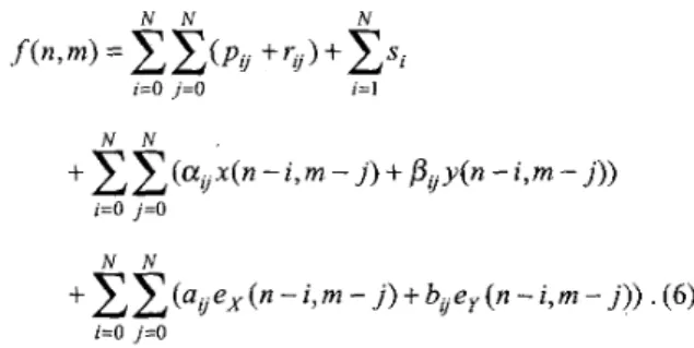
where M is the width of image, respectively. Thus, the mapping of Eq. ( 5 ) onto a systolic architecture isdepicted in Fig. 2. More importantly, this systolic structure has no global broadcast signals anywhere even though we implement the higher order 2-D IIR digital filters. In addition, one merely sets bv to zero such that a new systolic-array structure of an FIR digital filter can be obtained.
3. Comparison Results
Comparison results of IIR digital filters are tabulated in Table I. It is in terms of the critical cycle period, latency, the number of multipliers, delay elements, and, importantly, whether the input and output signals globally broadcast in these structures. In Table I,
r.1
denotes a minimum integer that greater than or equal to,
and T, and To represent the operation time required for the multiplier and adder, respectively. So as to minimize periods in the critical paths as shown in [ 1-31 and Fig. 2,we properly apply tree method to those structures and then separately evaluate the critical periods. In our work, the resulting period is less than that in [ 11 for N 5 2 and [3]. For practical case, since M is much larger than N , the number of delay elements is dominated by the product- term MN
.
Hence, the number of delay elements in thiswork is.almost equal to that of [2] as well as [3], and less than that of [ l ] . Analogously, we compare the performance of these FIR filters as listed in Table I1 after setting bu to zero. From Tables I and 11, we guarantee that the proposed structures have no global broadcast and maintain the lowest latency under the accepted critical cycle period.
4. An FIR Filter Combined with the Lower-Error Fixed-Width Multiplier
We have successfully proposed the new IIR and FIR digital filters in the word level. For more practical considerations, we should take them down to the logic- gate level and apply the recently developed lower-enor fixed-width multiplier [4] as shown in Fig. 3. In Fig. 3,
ai. and x i are the t -th bits of the coefficient,. au
,
and input signal, x q , respectively.pt
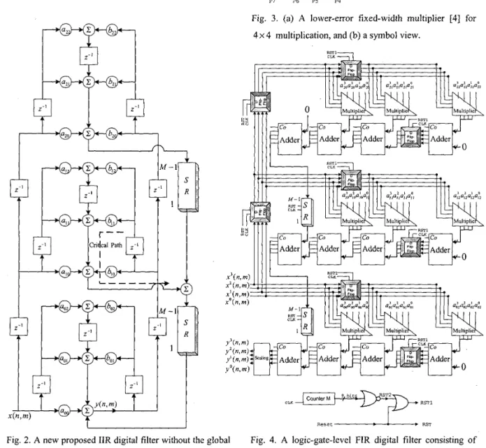
denotes the t -th bit of the product P of the multiplier. For simplicity, we only present 4-bit operation of a new 2-D FIR digital filter while receiving a 512x512 image for N = 2 andA4 = 512. That is, we require the 4 x 4 fixed-width multiplier, 4-bit adder, 4-bit D-flip-flop and shift-register with the size of ( M - 1) to implement a 2-D FIR filter as shown in Fig. 4. For the sake of the prevention of overflow, we normalize the value of input sequence and confirm that the sum of the absolute values of all coefficients is less than one. On the other hand, the output bits after the last stage adder must shift one-bit left in the scaling box to obtain correct binary point position as the next subsystem input bits. Thus, we only need 4 bits for the output bits. In addition, we need a counter, which counts the number from 0 to 511,to produce the signal R S T 2 . Then,
RSTl is obtained through the OR gate whose inputs are
RST2 and RST. Some specified D flip-flops in Fig. 4 are connected to the signal RSTl and other D flip-flops are connected to the signal RST for the purpose of synchronization. This logic-gate-level structure is more suitable to the implementation via VLSI technology or well-developed ICs such as TTL ICs or CMOS ICs.
5. Error Analysis in New Digital Filters
In this section, we additionally reveal the brief results for the error analysis due to finite precision arithmetic in 2- D IIR digital filters. Here, we adopt the same notations as in [ 5 ] , and we directly extend the representation in [ 3 , 51.
Since we normalize the value of input sequence and confirm that the sum of the absolute values of all coefficients is less than one, the number of
( N
+
1) x ( N+
1) storage errors can be easily eliminated and only N storage errors are residual due to addition of each I-D filter output. However, this concept increases coefficients quantization; that is, it will be a tradeoff between coefficients quantization error and storage error. Thus, the total combined errors are written asN N
Parameters Critical Cycle Period
In Eq. (6), altemately, the roundoff errors due to finite precision multiplication can be significantly reduced while applying a fixed-width multiplier with lower average error and lower variance compared to other multipliers [4]. Other terms will be identical to those in other proposed architectures while restricting the sum of absolute values of all coefficients is less one.
Sid-Ahmed [ I ] SCH3 of S-G-A [2] Shanbhag [3] This Work
r,
+(2 +r10g2(N+1))ra
T, +2T, 2T,+
2T, T, +3T,6. Conclusions
The new systolic-array architectures for the implementation of 2-D IIR and FIR filters have been accomplished by reordering the delay elements as well as summations and by applying another systolic transformation. The realization yields locally broadcast and lowest latency without sacrificing the number of
Global Broadcast No. of Multipliers
Latency
multipliers and delay elements under the accepted critical cycle period. In addition, we provide a detailed logic-gate level block diagram of a 2-D FIR filter, which is suitable to imagelvideo processing applications due to the lower quantization effect in finite precision multiplication.
Input and Output Input and Output Input and Output No
1 1 0 0 2(N
+
1)2 - 1 2 ( N+
- 1 2(N+
1)2 - 1 2(N+1)2 -1 References ( N ++
2MN No. of Delay ElementsM. A. Sid-Ahmed, “A systolic realization for 2-D digital filters,” IEEE Trans. Acoust., Speech, Signal Processing, vol. ASSP-37, pp. 560-565, Apr. 1989. S. Sunder, F. El-Guibaly, and A. Antoniou, ”Systolic implementations of two-dimensional recursive digital filters,” in Proc. IEEE Int. Symp. Circuits Syst., May
N. R. Shanbhag, “An improved systolic architecture for 2-D digital filters,” IEEE Trans. Signal Processing,
vol. 39, no. 5, pp. 1195-1202, May 1991.
L. D. Van, S. S. Wang, S. Tenqchen, W. S. Fegn, and B. S. Jeng, “Design of a lower error fixed-width multiplier for speech processing application,” in Proc. IEEE Int. Symp. Circuits Syst., May 1999, vol. 3, pp. 130-1 33, Orlando, Florida.
D. Raghuramireddy and R. Unbehauen, “A systolic structure for complex digital filters,” in Proc. IEEE Int. Symp. Circuits Syst., May 1990, pp. 1252-1255.
1990, pp. 1034-1037.
( N + 1)2 + ( M
+
l)N 3N(N + 1) + MN1
3N(; + I )+
( M+
l 2
Table I Comparison Results among the IIR Architectures
Table I1 Comparison Results among the FIR Architectures
(a) (b) (c) Fig. 1. Systolic transformation, (a) applied by this paper, (b) applied by [3], and (c) original second-order relation
4
L ND-ND 4 P7 P6 P5 P4 A-A Cell4
4
Fig. 3. (a) A lower-error fixed-width multiplier [4] for
4 x 4 multiplication, and (b) a symbol view.
CounterM bit
cLK=++7=
RST1 R e s e t - RSTFig. 2 . A new proposed IIR digital filter without the global broadcast for N = 2 .
Fig. 4. A logic-gate-level FIR digital filter consisting of the fixed-width multiplier for N = 2 .