This content has been downloaded from IOPscience. Please scroll down to see the full text.
Download details:
IP Address: 140.113.38.11
This content was downloaded on 28/04/2014 at 07:57
Please note that terms and conditions apply.
Liquid Crystal Alignment with a Photo-Crosslinkable and Solvent-Soluble Polyimide Film
View the table of contents for this issue, or go to the journal homepage for more 2000 Jpn. J. Appl. Phys. 39 L471
(http://iopscience.iop.org/1347-4065/39/5B/L471)
Jpn. J. Appl. Phys. Vol. 39 (2000) pp.L471–L473 Part 2, No. 5B, 15 May 2000
c
°2000 The Japan Society of Applied Physics
Liquid Crystal Alignment with a Photo-Crosslinkable and Solvent-Soluble Polyimide Film
Wen-Chin LEE, Chain-Shu HSUand Shin-Tson WU1Department of Applied Chemistry, National Chiao Tung University, Hsinchu, Taiwan 30050, R.O.C.
1HRL Laboratories, LLC, 3011 Malibu Canyon Road, Malibu, CA 90265, U.S.A.
(Received March 6, 2000; accepted for publication April 12, 2000)
A new photo-crosslinkable and solvent-soluble polyimide containing cinnamate side chains (PICA) was developed for aligning nematic liquid crystals (LCs). Good LC alignment was achieved by exposing a long-wave linearly polarized ultraviolet (LPUV) light to the PICA film. The LC alignment direction is found perpendicular to the polarization axis of the incident LPUV light. The uniform alignment of LC molecules induced by PICA films remains intact after being heated at 85◦C for 450 hours. A small pretilt angle on the PICA film was generated by the double exposure method.
KEYWORDS: liquid-crystal display, photoalignment, UV, polyimide, cinnamate
L471 1. Introduction
Multi-domain is a promising approach for widening the viewing angle of a liquid crystal display (LCD) device.1)
Fab-ricating multiple domains using standard rubbing processes is complicated and might cause static charges, contamination, or scratches. As a result, the manufacturing yield is reduced. To overcome these problems, photo-induced LC alignment using linearly polarized ultraviolet (LPUV) light has been developed.2, 3)Some photo-reactive polymers containing azo
compounds4, 5)and polyvinyl cinnamate derivatives,3, 6–8)and
polyimides (PIs)9, 10) have been demonstrated as alignment agents and phase retardation films11, 12) for wide view angle. Among these alignment agents, only PI possesses good ther-mal stability. However, in order to generate LC alignment using PI films, a short wave (λ = 254 nm) UV is needed for exposure. When these photo-reactive PIs are irradiated by the high-energy UV photons, their backbones are decom-posed and charge trapping centers on the LC and PI interfaces are formed. The trapped ions would degrade the resistivity of the LC mixture and then cause undesirable flickers and im-age sticking during active matrix addressing.13) So, there is
an urgent need to develop new photo-reactive polymers that are free from trapping centers while exhibiting good thermal stability.
In this paper, we report a new polyimide that incor-porates the photo-reactive cinnamate group into its side chain. The new polyimide (abbreviated as PICA) is photo-crosslinkable and exhibits good solubility in polar sol-vents such as N-methylpyrrolidone, N,N-dimethyl acetamide, γ -butyrolactone, 2-pentanone, and tetrahydrofuran. Two out-standing features of this PICA film deserve special mention: 1. It uses long wave UV (λ ∼ 350 nm) for exposure. As a result, the PI backbone is not decomposed and no charge trapping centers are formed. 2. It is solvent soluble and the curing temperature is relatively low. The latter is particularly attractive for low temperature poly-silicon thin-film-transistor (TFT) LCD application.
2. New Polyimide
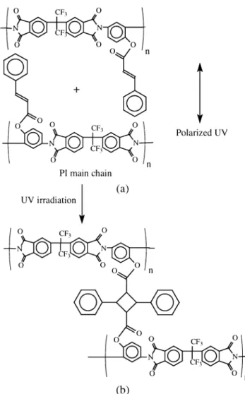
The structure of PICA is depicted in Fig. 1. The synthesis involves esterification of hydroxy group of PIOH [hexafluoro-isopropylidene diphthalic anhydride (6FDA)-2,4 diaminophe-nol] with cinnamoyl chloride. The PIOH was prepared by the poly-condensation reaction with 6FDA and 2,4 diaminophe-nol. The molecular weight of PICA determined by the
gel-Fig. 1. Chemical structures of the PIOH, PICA and dichroic azo dye used for alignment studies.
permeation chromatography is about 1.2 × 10⁵and it exhibits
a glass transition at 264◦C. Since PICA is solvent-soluble, its film can be fabricated from solution by evaporation of sol-vent without curing at high temperature. To prepare align-ment layer, we first dissolved PICA in 2-pentanone and then spin-coated the solution onto indium-tin-oxide (ITO) glass substrates. After baking at 120◦C for 10 minutes, a trans-parent film on the ITO-glass was obtained. We measured the absorption of the film coated on a quartz substrate and found that no absorption in the visible region.
The photo-induced alignment process was performed us-ing the long wave (λ = 350 nm) UV light (Rayonet Photo-chemical Reactor, Model #RPR-100). An Oriel UV linear dichroic polarizer (Model #27320) was used to polarize the incoming light. The light intensity at the sample surface was measured to be about 0.65 mW/cm2. This LPUV light was
used to illuminate the PICA-coated glass substrates from the PICA film side. When the cinnamate group side chain is ex-posed to the long wave LPUV light, it undergoes the (2+ 2)
photo-dimerization reaction.14) The PICA film aligning LC
molecules through this mechanism can greatly reduce the de-composition of PI backbones because of the lower energy UV photons involved. A homogeneous or twisted-nematic (TN) cell could be assembled using two substrates coated with such PICA alignment layers.
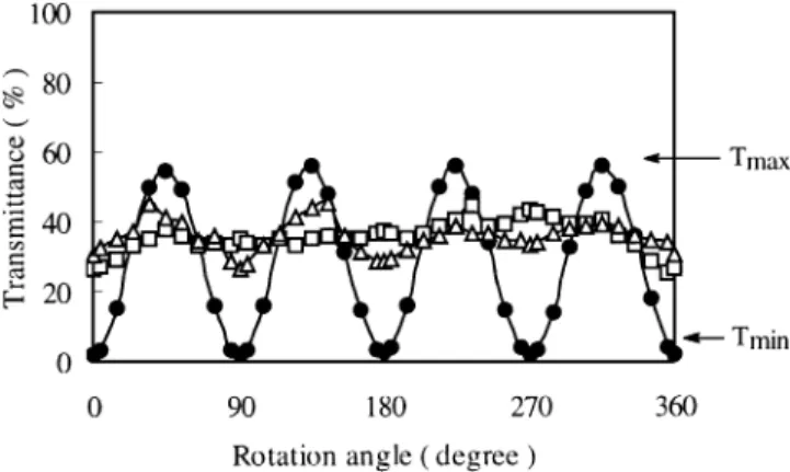
We first prepared a homogeneous cell and filled it with 5CB (4-cyano-40-n-pentyl-biphenyl) liquid crystal. The cell gap was measured to be 25µm. To monitor the alignment qual-ity, we measured the polar angle dependent light transmit-tance through the test cell sandwiched between two crossed polarizers. Three types of alignment layers were prepared for comparison: PIOH exposed to LPUV light at 2 J/cm2, and two PICA films exposed at 0 J/cm2and 2 J/cm2, respectively. Results are shown in Fig. 2.
The data shown in Fig. 2 were measured from a polarizing microscope. A broadband incandescent lamp was used as il-luminating light source. The beam diameter at LC cell was about 5 mm. The 100% transmittance in Fig. 2 means that the two polarizer axes are parallel. The light transmittance of the cell with unexposed PICA films displayed no distinct angular dependence. This indicates that no preferred LC alignment direction is formed. For the cell using PIOH alignment layers (exposed at 2 J/cm2), some low contrast maximum and
mini-mum start to appear. On the cell comprising of PICA align-ment layers (exposed at 2 J/cm2), clear maximum and mini-mum transmittance exist and repeat regularly at 90◦interval. These are direct evidences of a homogeneous alignment. The Tmax/Tminratio was found to be about 30. This relatively low
contrast ratio is because the light source is broadband and not collimated. In a separate measurement using a HeNe laser beam, the contrast ratio was found to exceed 100. Such a high contrast ratio implies that the photo-induced alignment is indeed unidirectional.
Thermal stability is a critical concern of the photo-induced alignment. Without satisfactory stability, the non-rubbing photo-alignment technique is difficult to justify its practical significance. The ratio of Tmax/Tmin shown in Fig. 2 can be
used as an indicator for qualitatively assessing the thermal stability of photo-alignment.15)To simulate the active matrix display, we have prepared a test cell using the described PICA alignment layers and filled with a super-fluorinated high
resis-Fig. 2. Angular-dependent light transmittance of a test cell prepared with (4) PIOH films, (¤) PICA films, and (●) PICA films exposed to a linearly polarized UV light of 2 J/cm2, 0 J/cm2 and 2 J/cm2, respectively. Data
were measured from a polarizing microscope. LC cell = 25 µm-thick 5CB.
Fig. 3. Thermal stability of a test homogeneous cell prepared with the LPUV-exposed PICA films. LC mixture: ZLI-4792 and T= 85◦C.
Fig. 4. Polar diagrams of a guest-host cell (a) before and (b) after LPUV exposure atλ = 350 nm. The arrow in curve (b) corresponds to the polar-ization axis of the LPUV light impinging on the PICA films.
tivity LC mixture, ZLI-4792. A typical specified storage tem-perature for LCD panels is from−40 to 85◦C. Thus, we chose to do thermal stability test at 85◦C. The test cell was kept in an 85◦C oven for most of time and taken out for measuring Tmax/Tminat room temperature for a short while. Such
heat-ing and coolheat-ing cycles were repeated for about twenty days. Results are depicted in Fig. 3. It was found that the Tmax/Tmin
ratio had no significant change after heating at 85◦C for 450 hours. This aging study shows that the PICA alignment layers we developed exhibit an excellent thermal stability.
From Fig. 1, the new PICA polyimide is different from PIOH by the cinnamate side-chain group. This cinnamate side chain apparently plays a crucial role in forming align-ment patterns. Without such side chain, the UV-treated PIOH films show ill-defined alignment direction. With this cinnamate side chain, the LPUV-exposed PICA films pro-vide a uniaxial alignment to the LC molecules. Thus, the cinnamate-incorporated polyimide has undergone anisotropic photo-crosslinking under LPUV exposure.14)
In order to determine the orientation direction of LC molecules with respect to the UV light polarization axis, we prepared a guest-host (GH) cell and measured its absorption dichrosim. In the GH cell, 1 wt% dichroic azo dye (with structure shown in Fig. 1) was doped in 5CB. The cell gap was measured to be about 25µm. The PICA films exposed at 2 J/cm2were used as alignment layers. The major absorp-tion axis of the dye was measured to be parallel to the LC directors.
Figures 4(a) and 4(b) show the polar absorption diagrams
of the guest-host cell at λ = 438 nm before and after the PICA films were exposed to LPUV light, respectively. Before the exposure, the absorption is isotropic in all polar angles indicating no preferred alignment direction has been gener-ated. After the exposure, a clear alignment direction occurred. From Fig. 4(b), this alignment direction is perpendicular to the polarization axis of the impinging UV light. Our result is consistent with those photo-alignments on photo-reactive polyimides9, 10)and azo-benzene polymers.4, 5)
3. Pretilt Angle
Pretilt angle is an important parameter for the electro-optic effects of a LCD device.16)A different display device may
re-quire different pretilt angle. For a TN-LCD, a pretilt angle ranging from 1 to 5 degrees is normally needed to prevent the reverse tilt disclinations. However, for the in-plane switch-ing mode, no pretilt angle is required.17, 18) Pretilt angle of
LPUV-irradiated PICA films can be generated by the double-exposure method6)where in the second exposure the substrate
was rotated 90◦with respect to the first and inclined at 70◦to the incoming LPUV light. Two TN cells were prepared us-ing the sus-ingle and double exposure methods. The cells were then filled with 5CB and biased at 4Vrms. In the TN cell using
single exposure of PICA films, disclination lines are present. However, in the double-exposure cell, the disclination lines
Fig. 5. Photo-dimerization model of PICA-induced LC alignment.
Jpn. J. Appl. Phys. Vol. 39 (2000) Pt. 2, No. 5B W.-C. LEEet al. L473
are completely eliminated. The pretilt angle generated in the double-exposure cell was measured to be about 0.1 degree using the crystal rotation method.19) An Autronic DMS 101
TBA instrument was used for characterizing the pretilt angle. The mechanism of LC alignment using LPUV-irradiated PICA films is attributed to the photo-dimerization of the cin-namate group side chains as depicted in Fig. 5. Figure 5(a) shows a possible molecular arrangement before UV expo-sure. The arrow indicates the direction of UV polariza-tion. During LPUV irradiation, the cinnamate molecules are crosslinked through dimerization. The crosslinked struc-ture (Fig. 5(b)) aligns the LC directors along its main chain axis (i.e., perpendicular to the polarization of the UV light) through anisotropic van der Waals interaction.20) This align-ment mechanism has been proposed in earlier literatures3, 6)
except for different polymer.
4. Conclusion
We have developed a new photo-crosslinkable and solvent-soluble side-chain polyimide (PICA) for photo-alignment of liquid crystals. The PICA films exhibit good solubility in several polar solvents, low curing temperature and excellent thermally stability while eliminating charge trapping centers. Useful applications for the in-plane switching and low tem-perature poly-silicon TFT-LCDs are foreseeable. The pretilt angle of the present PICA alignment films is somewhat too small. Methods for increasing pretilt angle are under investi-gation.
The HRL group is indebted to the financial support by AFOSR, under contract number F49620-98-C-0019
1) K. H. Yang: Conf. Record of the 11th Int. Display Research Conf. (San Diego, 1991) p. 68.
2) W. M. Gibbons, P. J. Shannon, S. T. Sun and B. J. Swetlin: Nature 351 (1991) 49.
3) M. Schadt, K. Schmitt, V. Kozinkov and V. Chigrinov: Jpn. J. Appl. Phys. 31 (1992) 2155.
4) P. J. Shannon, W. M. Gibbons and S. T. Sun: Nature 368 (1994) 532. 5) K. Ichimura, Y. Hayashi, H. Akiyama and T. Ikeda: Appl. Phys. Lett.
63 (1993) 449.
6) Y. Iimura, S. Kobayashi, T. Hashimoto, T. Sugiyama and K. Katoh: IEICE Trans. Electron. E79-C (1996) 1040.
7) N. Hasegawa, H. Ono, H. Takatsuka, T. Yamamoto and O. Sangen: Macromolecules 30 (1997) 6680.
8) K. Rajesh, S. Masuda, R. Yamaguchi and S. Sato: Jpn. J. Appl. Phys.
36 (1997) 4404.
9) X. Wang, D. Subacius, O. Lavrentovich, J. L. West and Y. Reznikov: SID Tech. Dig. 27 (1996) 654.
10) M. Nishikawa, B. Taheri and J. L. West: Appl. Phys. Lett. 72 (1998) 2403.
11) N. Kawatsuki, C. Suehiro and T. Yamamoto: Macromolecules 31 (1998) 5984.
12) N. Kawatsuki, T. Yamamoto and H. Ono: Appl. Phys. Lett. 74 (1999) 935.
13) K. H. Yang, K. Tajima, A. Takenaka and H. Takano: Jpn. J. Appl. Phys.
35 (1996) L561.
14) P. G. Egerton, E. Pitts and A. Reister: Macromolecules 14 (1981) 95. 15) Y. Wang, C. Xu, A. Kanazawa, T. Shiono, T. Ikeda, Y. Matsuki and Y.
Takeuchi: J. Appl. Phys. 84 (1998) 181.
16) J. Cognard: Mol. Cryst. & Liq. Cryst. Suppl. 1 (1982) 1. 17) Y. Zhou and S. Sato: Jpn. J. Appl. Phys. 37 (1998) 4439. 18) M. Oh-e and K. Kondo: Appl. Phys. Lett. 69 (1996) 623.
19) V. Witter, G. Baur and D. W. Berreman: Phys. Lett. A 56 (1976) 142. 20) K. Okano, N. Matsumoto and S. Kobayashi: Jpn. J. Appl. Phys. 21