pled control (CCC) significantly improves contouring accuracy for linear and circular contours. As geometrical and parametric curves become more popular in modern manufacturing, ma-chining processes with multiaxis motion systems are required, however, the available biaxial CCC cannot be directly applied to arbitrary contours with multiaxis machining systems. In this paper, we propose a novel approach for arbitrary contours by estimating the contouring error vector to efficiently determine the variable gains for CCC. Experimental results for a biaxial motion system indicate that the proposed approach efficiently yields variable gains similar to those in traditional CCC. Furthermore, results on a three-axis CNC machining center show that the present approach significantly improves motion accuracy in multiaxis motion systems.
Index Terms—Cross-coupled control, contouring error, cross-coupling gains, multiaxis motion systems.
I. INTRODUCTION
I
N MACHINING processes, motion precision depends on both tracking and contouring accuracy. Traditionally, tracking accuracy was improved by applying feedback and feedforward control loops to each axis individually. Poo et al. [1] analyzed relations between the feedback controller and the contouring error and concluded that the matched dc gain in feedback control design improves contouring precision. Feedforward control loops are also common in motion control design because they efficiently reduce the servo lag and, thus, decrease the contouring error [2]–[5]. In addition to feedback and feedforward control loops, the cross-coupled control (CCC) structure, which considers the mutual dynamic effects among all axes, was developed by Koren [6] to further reduce the contouring error. Various improved CCC designs have since been proposed [7]–[9].Recently, the variable-gain CCC was proposed by Koren and Lo [10], [11] to provide more precise contouring results by es-timating the magnitude and the direction of contouring errors for further compensation. For arbitrary contour applications, the variable-gain CCC estimates the contouring error by applying the circular contour approximation and compensates each axis
Manuscript received October 11, 2000. Recommended by Technical Editor H. Peng. This work was supported by the National Science Council, R.O.C., under Contract NSC 89-2212-E-009-015.
S.-S. Yeh was with the Department of Electrical and Control Engineering, National Chiao Tung University, Hsinchu, 300 Taiwan, R.O.C. He is now with the Mechanical Industry Research Laboratory, Industrial Technology Research Institute, Hsinchu, Taiwan, R.O.C.
P.-L. Hsu is with the Department of Electrical and Control Engineering, National Chiao Tung University, Hsinchu, 300 Taiwan, R.O.C. (e-mail: [email protected]).
Publisher Item Identifier S 1083-4435(02)02098-7.
variable-gain CCC works well for biaxial motion systems, but it is difficult to apply the available CCC design to multiaxis ma-chines that are gaining popularity in modern industries. Also, CCC needs an efficient algorithm to determine the variable gains of arbitrary contours in real time.
To improve contouring accuracy for multiaxis motion sys-tems, Lo [12] proposed an approach by transforming the coor-dinate to obtain the moving basis to form a feedback controller for a 3-axis motion system. Chiu and Tomizuka [13] proposed the task coordinated approach by considering all axes as the first-order loops to obtain the feedback and the feedforward con-trol loops. However, Lo’s approach is difficult to be applied to more than three axes and its tracking accuracy of the controller without a feedforward control loop can be further improved. On the other hand, performance of a simplified first-order design including an unreliable plant model by Chiu and Tomizuka is, thus, inherently limited as verified in [14].
In this paper, we propose a modified variable-gain CCC de-sign based on the contouring error vector by applying the linear contour approximation. The design can be directly extended to multiaxis motion systems. Theoretically, the contouring error vector is defined as a vector from the actual position to the nearest point on the contour. However, its computation is very complicated. In our approach, a vector from the actual posi-tion to the nearest point on the line that passes through the ref-erence position tangentially is adopted if the tracking error is minimized. Finally, experimental results on a 3-axis machining center show that the variable gains in multiaxis CCC are more efficiently obtained and contouring accuracy of the CNC is sig-nificantly improved by applying the proposed multiaxis CCC design.
II. THEVARIABLE-GAINCCC
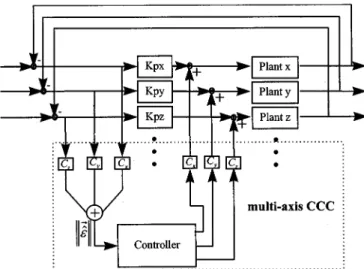
The biaxial motion control system with the variable-gain CCC is shown in Fig. 1. ( ) are position loop con-trollers, ( ) represent the controlled plants within the position loops, ( ) and ( ) denote reference posi-tion and the actual posiposi-tion, respectively. ( ) are the axial errors of each axis, denotes the estimated contouring error, ( ) are varying cross-coupling gains which depend on the tool path trajectory and is the cross-coupled controller.
Since an arbitrary contour can be approximated by a circular contour, let be the radius of curvature at the reference position and be the traversal angle of a circular motion. The esti-mated contouring error is obtained as
(1)
Fig. 1. Biaxial motion control system with variable-gain CCC [10], [11].
( ) denotes the center of curvature. Because the actual position ( ) can be represented as
(2) (3) by substituting (2) and (3) into (1), the estimated contouring error becomes
(4) If the radius of curvature is large enough and the contouring error is much smaller than the axial errors ( ), the esti-mated contouring error can be approximated by the Taylor’s expansion of (4), which is
(5) The cross-coupling gains ( ) are then
(6) (7) For a linear contour, the radius of curvature is infinite and the corresponding cross-coupling gains are
(8) (9) where denotes the incline angle of the linear contour.
For a circular contour, the cross-coupling gains are the same as (6) and (7), except denotes the circular contour traversal angle and is replaced by the fixed radius of the circular con-tour as
(10) (11) In general, all curve contours can be approximated by circular contours with different radii.
Fig. 2. Linear contour representation.
III. BIAXIALCONTOURINGERRORVECTOR A. Estimation of the Contouring Error Vector
In this section, we propose an estimation approach of the contouring error vector for obtaining the variable-gain vector in the biaxial CCC. This approach will be ex-tended to multiaxis motion systems as in Section IV. Consider the linear contour as shown in Fig. 2. is the incline angle of the linear contour. The normalized tangential vector of the
linear contour is . is the
normal-ized normal vector which is perpendicular to tangential vector are the axial errors. The tracking error vector is . is the contouring error. and denote the actual and the reference position, respectively. The contouring error can be directly obtained as
(12) where, is the inner product operator.
Define the contouring error vector as a vector from the ac-tual position to the nearest point on the contour trajectory as (13) The contouring error vector is, thus, a vector with contouring error and direction . Furthermore, the contouring error is the inner product of tracking error vector and the normalized normal vector , as shown in (12).
B. Determination of the Variable Gains
Comparing the cross-coupling gain vector in (8)–(9) and the normalized normal vector , note that the cross-coupling gain vector contains the corresponding el-ement of the normalized normal vector , represented as
(14) The contouring error vector of a linear command can be di-rectly obtained by (13). For arbitrary contour applications, the geometric relations among the desired contour, the actual posi-tion and the reference position in a biaxial motion systems are as shown in Fig. 3. In the present approach, the estimated
Fig. 3. Geometrical relations of biaxial motion systems [15].
contouring error vector is defined as the vector from the ac-tual position to the nearest point on the line that passes through the reference position tangentially with direction . Note that the estimated contouring error vector approximates the con-touring error vector well only with small tracking error [15].
Since the direction of the estimated contouring error vector is parallel to the normalized normal vector at the reference position , the magnitude of denoted as is, thus, defined as the inner product of the tracking error vector and the normal-ized normal vector .
Let the tangential vector and the normalized normal vector
be and , respectively. The vector can
be directly derived as
(15)
and the estimated contouring error is
(16) The estimated contouring error vector is then expressed as
(17) By comparing (17) and (13), the cross-coupling gains ( ) can be replaced by the elements of the normalized normal vector , as shown in (14).
IV. MULTIAXISCONTOURINGERRORVECTOR A. Estimation in Multiple-Dimensional Space
Consider the geometric relations among the arbitrary desired contour, the actual position and the reference position in three-dimensional space as shown in Fig. 4. Because it is dif-ficult to obtain the contouring error vector exactly, we adopt the estimated contouring error vector for obtaining the vari-able gains in the proposed multiaxis CCC. As shown in Fig. 4, the estimated contouring error vector lies on the plane ex-panded by the tracking error vector and the normalized tan-gential vector and perpendicular to the normalized tangential
Fig. 4. Geometrical relations of 3-axis motion control systems.
vector . In fact, as the tracking error is small enough, the contouring error vector can be closely approximated by the estimated contouring error vector . Define the normalized es-timated contouring error vector
(18) where
(19)
or (20)
(21) and is an inner product operator and is a 2-norm op-erator. The relation between and can be derived from (19)–(21) as
(22) By substituting (22) into (20), and are obtained as
in which the signs of and determine the direction of the normalized estimated contouring error vector . Because the angle between the normalized estimated contouring error vector and the tracking error vector is in general within 90 , 90 , the following condition holds:
(23) From (23), and can be further determined as
(24)
Fig. 5. Multiaxis motion control systems with multiaxis CCC.
B. Determination of Multiaxis Variable Gains
As shown in (18) and Fig. 4, the magnitude of the estimated contouring error vector is the inner product of the normal-ized estimated contouring error vector and the tracking error vector
(26)
The estimated contouring error vector is, thus, obtained as
(27) Following our analysis of the biaxial variable-gain CCC in Sec-tion II, the magnitude of the estimated contouring error vector is modulated by a controller and then is used to compensate for each axis along the direction of the estimated contouring error vector. The compensation direction for each axis is suitably determined by the cross-coupling gain vector in the present variable-gain CCC. Therefore, the cross-coupling gains can be obtained directly from the elements of the normalized estimated contouring error vector. Let the normalized estimated
contouring error vector be . The
cross coupling gains are, thus, directly determined as
Fig. 6. Experimental setup.
Fig. 7. Contour trajectory used in the biaxial experiments.
The proposed multiaxis CCC motion control system is shown in Fig. 5 and (Kpx, Kpy, Kpz) denote the position loop controllers for each axis of the motion system. From (21), we have
where is the angle between the tracking error vector and the normalized tangential vector . The singularity condition occurs when the tracking error vector is parallel to the nor-malized tangential vector . In practice, one should check that
Fig. 8. Experimental results for the proposed variable-gain CCC.
Fig. 9. Experimental results for the original variable-gain CCC.
V. EXPERIMENTS
The experimental setup of a three-axis DYNA 1007 CNC ma-chining center is shown in Fig. 6. A PC-486 generated the main control commands and recorded the signals including: the input commands for different contours, the implementation of a vari-able-gain CCC controller and the control inputs to the velocity loop of the AC servo motors. The PC-486 interface utilized an AD/DA card to send and receive the control inputs and position output, respectively, at a sampling period of 1 ms.
To identify the controlled plant for each axis, the axial control input was given a pseudorandom binary sequence (PRBS) and
the velocity control loops of the three axes was obtained using the ARX model as shown in the equations at the bottom of the previous page. To achieve both stable motion and matched gains for the uncoupled system [1], the feedback loop proportional gains ( ) were chosen as
To achieve significantly reduced tracking errors in applying the proposed approach, the optimal zero phase error tracking con-trol (ZPETC) was also applied to each axis [5].
A. Verification in Biaxial Motion
The well-tuned PID cross-coupled controller for the mo-tion control system is chosen to be [14]
The contour trajectory of the motion control system is shown in Fig. 7. The average speed is 853 mm/min, the maximum speed is 2500 mm/min and the minimum speed is 250 mm/min. Experimental results obtained by applying the proposed vari-able-gain CCC approach and the original varivari-able-gain CCC are also shown in Figs. 8 and 9, respectively. Fig. 8 shows the cross-coupling gains , the tracking error and the mea-sured contouring error of the proposed approach. Fig. 9 shows the cross-coupling gains , the tracking error, and the contouring error as in [10], [11]. Results are summarized in Table I.
As shown in Figs. 8, 9, and Table I, the experimental re-sults for our proposed variable-gain CCC are similar to those of the original variable-gain CCC by Koren and Lo [10], [11] except for the opposite sign of cross-coupling gain and , as indicated in (14). Compared to the operators for obtaining the variable gains for arbitrary contours, Table II indicates that implementing the proposed cross-coupling gains ( ) re-quires fewer operators than implementing ( ) in the orig-inal variable-gain CCC with circular approximation.
B. Application to 3-Axis Motion
The robust cross-coupled controller is designed by ap-plying the quantitative feedback theory (QFT) algorithm [16], [17] as
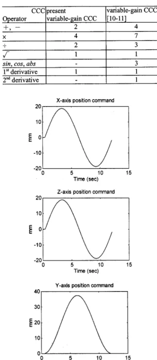
The position commands for each axis of the 3-axis motion control system are shown in Fig. 10. The commands perform an inclined circular contour with an 18.75 mm radius at a speed of 600 mm/min. The cross-coupling gains shown in Fig. 11 are the direction components of the estimated contouring error vector. The experimental results for the 3-axis CCC system are com-pared to those for the control system without CCC in Fig. 12 and in Table III. Because of the friction effect, results of the cross-coupling gains ( ) are discontinuous as the slip-stick phenomenon occurs as speed of any axis approaches
TABLE II
NUMBER OFOPERATORSUSED INIMPLEMENTATION OF THE
CROSS-COUPLINGGAINS
Fig. 11. Cross coupling gains of the 3-axis CNC.
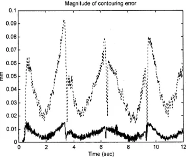
Fig. 12. Experimental results of the 3-axis motion control system.
zero. Fig. 12 and Table III indicate that the proposed 3-axis CCC effectively improves contouring accuracy. Note that the proposed algorithm can be directly applied to multiaxis motion systems.
VI. CONCLUSIONS
Although the CCC is known to effectively improve con-touring accuracy in motion systems, it is difficult to apply the original biaxial variable gains to multiaxis CCC. Also, the original CCC is inefficient to obtain the variable gains for arbitrary contours. In this paper, we developed a multiaxis variable-gain CCC design which is based on the contouring error vector approach. Experimental results for a biaxial motion system show that the proposed CCC approach and the original variable-gain CCC obtain similar variable gains. However, the present approach is more efficient. The proposed multiaxis CCC system was also applied to a 3-axis CNC machining center. Experimental results indicate that with the proposed variable gains, the multiaxis CCC control significantly im-proves contouring accuracy.
REFERENCES
[1] A. Poo, J. G. Bollinger, and W. Younkin, “Dynamic error in type con-touring systems,” IEEE Trans. Ind. Applicat., vol. IA-8, pp. 477–484, July/Aug. 1972.
[2] M. Tomizuka, “Zero phase error tracking algorithm for digital control,”
ASME Trans. J. Dyn. Syst., Meas. Contr., vol. 109, pp. 65–68, 1987.
[3] T. C. Tsao and M. Tomizuka, “Robust adaptive and repetitive digital tracking control and application to a hydraulic servo for noncircular ma-chining,” ASME Trans. J. Dyn. Syst., Meas. Contr., vol. 116, pp. 24–32, 1994.
[4] J. Z. Xia and C. H. Menq, “Precision tracking control of nonminimum phase systems with zero phase error,” Int. J. Contr., vol. 61, no. 4, pp. 791–807, 1995.
[5] S. S. Yeh and P. L. Hsu, “An optimal and adaptive design of the feed-forward motion controller,” IEEE/ASME Trans. Mechatron., vol. 4, pp. 428–439, Dec. 1999.
[6] Y. Koren, “Cross-coupled biaxial computer for manufacturing systems,”
ASME Trans. J. Dyn. Syst., Meas. Contr., vol. 102, no. 4, pp. 265–272,
1980.
[7] H. Y. Chuang and C. H. Liu, “A model reference adaptive control strategy for improving contour accuracy of multiaxis machine tools,”
IEEE Trans. Ind. Applicat., vol. 28, pp. 221–227, Jan./Feb. 1992.
[8] P. K. Kulkarni and K. Srinivasan, “Cross-coupled control of biaxial feed drive servomechanisms,” ASME Trans. J. Dyn. Syst., Meas. Contr., vol. 112, no. 2, pp. 225–232, 1990.
[9] Y. Koren and S. Jee, “Fuzzy logic cross-coupling control,” CIRP
Pro-ceedings-Manufacturing Systems, vol. 25, no. 1, pp. 104–108, 1995.
[10] Y. Koren and C. C. Lo, “Variable gain cross coupling controller for contouring,” CIRP Proc.-Manufacturing Systems, vol. 40, pp. 371–374, 1991.
[11] , “Advanced controllers for feed drives,” CIRP
Proc.-Manufac-turing Systems, vol. 41, no. 2, pp. 689–698, 1992.
[12] C. C. Lo, “Three-Axis contouring control based on a trajectory coordi-nate basis,” ASME Int. J. Series C-Mech. Syst. Mach. Elements Manuf., vol. 41, no. 2, pp. 242–247, 1998.
[13] G. T. C. Chiu and M. Tomizuka, “Contouring control of machine tool feed drive systems: A task coordinate frame approach,” IEEE Trans.
Contr. Syst. Technol., vol. 9, pp. 130–139, Jan. 2001.
[14] Y. Y. Chang and P. L. Hsu, “The design of precise motion systems by applying both the advanced controllers and the interpolators,” in Proc.
6th Int. Workshop Advanced Motion Control, Nagoya, Japan, Mar. 2000,
ical engineering and the M.S. and Ph.D. degrees in electrical and control engineering from National Chiao Tung University, Hsinchu, Taiwan, R.O.C., in 1994, 1996, and 2000, respectively.
He is currently a Researcher at the Mechanical Industry Research Laboratory, Industrial Technology Research Institute, Hsinchu, Taiwan, R.O.C. His research interests include motion system and control design.
of the department. His research interests include mechantronics, CNC motion control, servo systems, and diagnostic systems.
![Fig. 1. Biaxial motion control system with variable-gain CCC [10], [11].](https://thumb-ap.123doks.com/thumbv2/9libinfo/7617375.131003/2.918.77.415.100.292/fig-biaxial-motion-control-variable-gain-ccc.webp)