COMPUTER VISION, GRAPHICS, AND IMAGE PROCESSING 52, 210-238 (1990)
Three-Frame Corner Matching and Moving Object
Extraction in a Sequence of Images
HSI-JIAN LEE*
Department of Computer Science and Information Engineering, National Chiao Tung University, Hsinchu, Taiwan, 30050
AND HSI-CHOU DENG
Department of Information Science, National Chiao Tung lJniuersi& Hsinchu, Taiwan, 30050
Received November 28, 1988; accepted October 9, 1989
This paper presents a three-frame matching method for finding the correspondences of comer points. After a two-stage corner detector is applied to each frame to extract a set of corner points as the matching primitives, candidate transition paths, which are formed by three corner points among three consecutive corner sets, are found by utilizing the smooth- ness constraint of motion due to inertia. Initially, each transition path is assigned an initial probability of being correct transition based on the similarity of curvatures of the three corner points. These probabilities are iteratively modified by a relaxation process according to the consistency properties of both acceleration and velocity. After several iterations, the paths with sufficiently high probabilities are taken as the correct transition paths. A new segmentation process which integrates both velocity and contrast information is presented to extract regions of moving objects. Several experimental results show that the approach is very effective. 0 1990 Academic Press, Inc.
1. INTRODUCTION
Dynamic scene analysis is mainly concerned with the processing of time-ordered sequences of images for recovering motion parameters of the sensor and moving objects and determining object structures. The applications include traffic control, mobile robot navigation, computer animation, dynamic industry process monitor- ing, and so on. Several surveys can be found in [l-41.
The correlation method [5-71 for template matching is one of the commonly adopted approaches in earlier researches. This approach cannot conquer the problem of geometrical distortions. Another approach that can, divides motion analysis into two phases: computation of optical flow and interpretation of this field [3]. The term optical flow represents the displacement vectors of image elements from one frame to the next; it can be computed by using either the gradient-based techniques [8] or the primitive-based methods [9, 101. This ap- proach generally includes a matching process for tracking feature primitives such as corner points from frame to frame in a sequence of images. It is the main theme of this paper.
In primitive-based methods, many researchers adopt the relaxation technique to match corners extracted from two image frames [lo-121. These methods first estimate an initial probability of each possible matching pair. Then this probability
*To whom all correspondences should be sent. 210 0734-189X/90 $3.00
Copyright 8 1990 by Academic Press, Inc. All rights of reproduction in any form reserved.
THREE-FRAME CORNER MATCHING 211 is updated iteratively based on some criteria, such as the consistency property used in [lo]. Other features, such as edges and segmented regions, are also used as matching primitives [7, 13-151. These methods have good results if the extraction of primitives is nearly perfect.
For the interpretation of optical flow, the displacement field should be seg- mented into multiple partitions, which correspond to multiple moving objects in a scene. Potter [16] grouped points with the same velocity measures. Thompson [17] adopted a gradient-based method proposed by Fennema and Thompson [181 to estimate the velocity field. Then the velocity field are segmented based on the similarities of both brightness and motion. These methods are not satisfactory for complex motion with rotation and scaling. Adiv [19] used the Hough transforma- tion technique to segment the velocity field generated by several moving objects. It requires a great amount of computational cost.
The methods mentioned above for finding the displacement field work with only two frames at a time. Consequently, they do not make good use of the time-flow information. In comparison, human beings use this information on their retina to detect motion and separate multiple moving objects. Experiments with human perception on dot patterns show that the perception of a rigid object motion is extremely noise sensitive when only two frames are presented [201. Human beings also have difficulty in decomposing objects with different motion parameters in only two scenes.
Using three or more consecutive frames for motion analysis has been addressed by many researchers [21-261. Shariat and Price [22] showed that correspondences of three points in three frames or two points in four frames are sufficient to estimate the translation and rotation parameters. Jain and Sethi [231 showed that a trajectory interpolated by the curve-fitting techniques can result in a better resolution than the two-frame matching method does. A longer sequence of frames also makes better use of time-flow information for estimating the motion parame- ters. Jensen [24] proposed an approach for establishing correspondences in a binocular image sequence. He suggested the use of smoothness of velocity. Sethi and Jain [25] used the smoothness of motion due to inertia to solve the motion problem for arbitrary motion of several non-rigid objects in a scene. Yen and Huang [26] showed that if the correspondence of a single point is available over three frames, the rotation parameters can be determined.
Although multiple-frame methods make use of the time-flow information effec- tively, they often need to analyze many frames for good results. For example, the matching methods in [23, 251 have good results only after analyzing a long sequence of about ten frames. These methods are not satisfactory for some real-time monitor systems. Therefore, we conjecture that a three-frame matching algorithm will make use of the time-flow information more effectively than do the two-frame methods.
Segmentation is a process of partitioning an image into meaningful parts such that all points belonging to a part have some common properties and can be represented by a mathematical or logical predicate. Early systems [27] segmented images by utilizing only intensity values. Later, domain-dependent knowledge was used by Riseman and Arbib [281 in the design of a segmentation system. The results obtained by these systems were satisfactory for only a limited class of pictures. Since Braunstein [29] suggested that motion is a powerful cue for
212 LEE AND DENG
segmentation, many researchers are concerned with the use of motion information for segmenting images [16-18, 30-321.
We first extract three comer sets in three consecutive frames by a two-stage corner detector. This detector is described in detail in Section 2. Then, the three-frame matching method is presented. It utilizes the property of smoothness of motion to find all possible transition paths and adopts a relaxation process to determine the real matching paths, based on the consistency property due to spatial continuity. The details are illustrated in Section 3. After the transition paths are found, a region-merge method is proposed to extract regions of moving objects in each frame. This method utilizes both contrast and velocity information. The method is divided into two parts, object motion with and without scaling, and is depicted in Section 4. Several experimental results are given in Section 5. Some conclusions are presented in Section 6.
2. TWO-STAGE CORNER DETECTION
Detecting the position of a corner point accurately is an important process for dynamic scene analysis. Fang and Huang [33] proposed that the accuracy of the coordinates of the points has a big impact on the accuracy of motion parameters. They first located the edge positions with subpixel accuracy. Then, the corner positions are calculated by intersecting these edges. This method requires a great amount of computational cost and is not suitable for objects with curved surfaces. One commonly employed corner operator is presented by Moravec [34]. The operator selects image points with the highest variance in four directions as interest points. It would suffer from choosing some redundant points, such as edge points and noise. Furthermore, since it could not detect the real corner points precisely, it would decrease the accuracy of the smoothness measures in subse- quent analyses. Other corner detectors based on curvature and gradient changes can be found in [35, 361. Because the three-frame matching method uses both first and second derivatives, it is important to find all the corresponding points accurately.
In this system, the Moravec interest operator is first adopted to select interest points because it is simple and powerful. Some corner points may be defeated by other non-corner points with higher variances. In order to avoid missing these corner points, the local maximum filter is chosen with a small 3 x 3 window. This
would result in a great amount of redundant points. Also some interest points will locate on the neighborhood of the tip of a real corner point. We will cope with these problems below.
By observations, we find that most corner points often locate on the boundary of two or more than two regions whose average intensity values have significant difference. The corner points are junctions of L-type, arrow-type, K-type, and so on [37]. In this paper, only corner points of the L-type are considered. Actually, the method presented here can be extended to other types of corner points.
In the second stage, a clustering method is applied to classify the pixels within the window centered on the interest point. The corner point shown in Fig. 1 is located in the 9 X 9 window whose center is an interest point. The number within
each cell denotes the intensity value of the image point. We find that the average intensity values of the two regions have significant difference.
THREE-FRAME CORNER MATCHING 213
FIG. 1. Window of 9 x 9 pixels centered on an interest point.
Formally, let P = (pi(x, y), i = 1,2,. . . , N] be the set of interest points ex- tractedinthefirststage,andG,={p(x+k,y+1),k= -4 ,..., 4,1= -4 ,..., 4) designate the set of pixels in the window centered on the interest point pi(x, y) for a real corner point c. The 2-means clustering algorithm [38], adopted to classify the point set Gi into two clusters C, and C,, is described detailedly below.
Initially the algorithm partitions arbitrarily Gi into two clusters and computes two average gray values llzi and m2. Then it selects a point p from Gi and assigns it to the cluster whose mean value is closer to the gray value of point p. The algorithm keeps updating the mean values and assigning corner points until a complete scan of Gi with no change of the mean values. In our implementation, one of the following two pairs of points, (p(x - 4, y - 4), p(x + 4, y + 4)) and {p(x - 4, y + 4), P(X + 4, y - 4)], which has greater difference of intensity values, is selected as the initial two clusters. For the example shown in Fig. 1, the latter is selected. After clustering, noise points may be detected because they are often isolated, whose surrounding points are assigned to a different cluster.
After the pixels in the window centered on pi are clustered, the boundary passing through the corner point can be detected easily. We trace the boundary B,
{bi, i = 1,. . . ) I}, and calculate the curvature of each boundary points by using the
k-curvature algorithm [39]. The boundary point bj with the maximum curvature is taken as the real corner point, instead of the interest point pi. Because the curvature calculated by the k-curvature (k = 2) algorithm is noise sensitive and this measure affects later processing significantly, the curvature ci of the adjusted
214 LEE AND DENG
corner point bj is defined to be the angle between the two vectors bibI and 6&, where b, and 6, denote the two end points of the boundary.
In Fig. 1 the cell with two star symbols represents an interest point. The cells labeled with bj, j = 1,. . . , 13, represent the boundary points which pass through the real corner point. The point b, which has the maximum curvature, calculated by the 2-curvature method, is taken as the real corner point and is used to replace the interest point. The new curvature of point 6, is calculated by using the two vectors b761 and b7b,,; here, it is 90”.
After adjusting the position of interest points, we remove redundant edge points and pseudocorner points. Here, the edge points are defined as the points with curvature greater than a threshold t, t = 170, and the pseudocorner points are caused by the shadow of objects or the highlight. They generally are located on the boundary between two regions whose intensity values are similar.
3. THREE-FRAME MATCHING METHOD
Matching two or more pictures of the same scene is a common problem in computer vision and image processing. This problem arises in connection with registering pictures obtained by different sensors or by the same sensor at different times. In this paper, corner points are used for matching the images taken at different times by a stationary camera.
3.1. Smoothness Constraint and Candidate Transition Paths
In general, the projection of a smooth 3D trajectory is a smooth 2D trajectory in both orthographic and perspective projections. If a dynamic scene is sampled at a rate fast enough to capture all significant events in the scene, the observed motion of all objects will be smooth. Two frames are not enough to apply the smoothness constraint of motion. In this paper we use three frames to compute the change of motion.
According to the smoothness constraint, we select a candidate transition path in three frames which does not change abruptly. We determine whether a transition path satisfies the smoothness constraint by checking the changes of the velocity vectors. A displacement vector formed by corner points in the first two frames will be rejected if there is no supporting corner point in the third frame. From this property, we can remove many redundant transition paths which change abruptly in three consecutive frames. This would remove many wrong transition paths and thus reduce the computational cost.
Formally, assume that the three sets of corner points of three consecutive frames are P,, P2, and P3. A transition path m(p,, p2, p3), where p1 E P,, p2 E P2, and
p3 E P3, would be selected if the two displacement vectors p1p2 and pzp3 have similar directions and magnitudes. In detail, for any corner point p1 E P,, we find each possible matching point p2 E P2 which is located in a window centered on pI
with radius R. Then for the matching pair p1 and pz, we use the displacement vector p1p2 to predict the position of a comer point q in frame 3. A point p3 E P3
in the window centered on q with a small radius r (r I RI is searched. If it is found, the transition path m(p,, p2, p3) would be selected. Otherwise, the match- ing pair p, and pz will be rejected. Sometimes, these matching pairs which have no supporting point in frame 3 are due to noise and occlusion.
THREE-FRAME CORNER MATCHING 215 Then, these transition paths are tested whether they satisfy the smoothness constraint. We prefer the paths with small changes of direction and magnitude between the two displacement vectors p1p2 and p2p3. Here, the change of
direction @ is defined as the angle between plpz and p2p3, and the change of - - magnitude 1I’ is defined as the relative difference of lengths between p1p2 and p2p3
with respect to the length of plpz. The transition paths whose @ or q are greater than the predefined thresholds are rejected.
3.2. Consistency Property and Relaxation Process
The three-dimensional spatial continuity of object surfaces will constrain the two-dimensional spatial distribution of the displacement vectors of the feature points in the image plane. For the three-frame approach, we exploit the fact that the spatial continuity constrains the spatial distribution of acceleration vectors in the image plane; here, the acceleration vector is defined as the change of two displacement vectors in the three frames.
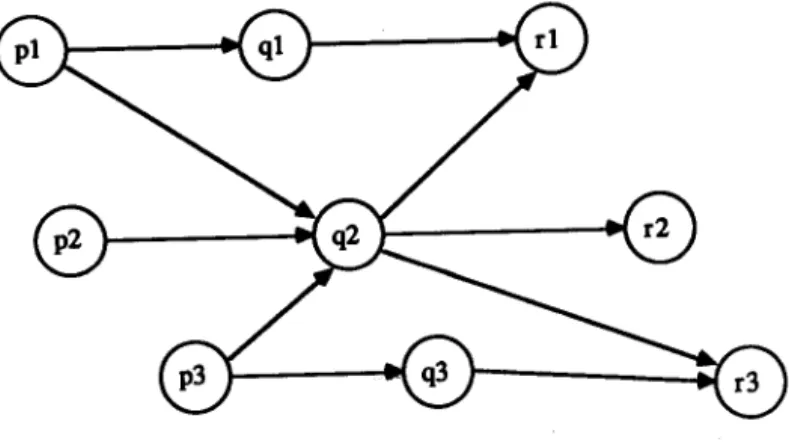
Formally, the consistency property is defined as neighboring points in a moving object that have similar characteristic vectors of motion, such as velocity and acceleration. This property can be used to suppress false matches which have no supporting paths. The transition path which has more neighboring transition paths with similar motion vectors has higher consistency. The transition paths with sufficiently higher consistency measure as taken as the candidate transition paths and the paths with lower consistency measure are removed. Figure 2 demonstrates the consistency property. In this figure there are three points in three different frames. The transition path m(p,, ql, rl) has two supporting transition paths,
m(p,, qz, r2) and m(p,, q3, r3), with similar velocities and accelerations, while the transition path m(p,, q2, rJ has no supporting transition path. Thus, the consis- tency measure of m(p,, ql, ri> should be higher than that of m(p,, q2, r3). Simi- larly, the transition path m(p,, q3, r3) has higher consistency measure than that of m(p,, q2, rl).
After the candidate paths are selected, we should refine the transition paths by a relaxation process based on the consistency property. First, we estimate the probability that a candidate path is correct. Assume that each corner point ci in
216 LEE AND DENG
frame 1 is associated with a set Mi of candidate transition paths. The transition path mj in Mi contains the coordinates of three corresponding corner points CxjlY Yjl)? cxj2, Yj*), and (xj3, yj3). Let the probability pj(mj) denote the probability that the transition path mj is correct. And let pi(m,) mean the probability that there is no transition path passing through corner point ci.
The initial probability py(mj) is defined to be the similarity of the curvatures of the three corner points in the transition path mj. This measure is selected because it is less sensitive to intensity changes. The similarity of intensity values is not taken into consideration because the illumination in three consecutive frames is not controllable and is easily affected by scale change and geometrical distortion. Lf2t vj,l, vj,2, and vj s denote the curvatures of the three corners in the transition path mj. The weight associated with the transition path mj of corner point ci is defined as wi(mj) = 1 -
lvj,l - 'j,zl + Ivj,2 - vj,31
2xd 1 where d representsmax(Ivj,l - 'j,21 + Ivj,2 -
Vj,ll). iAssume that the larger the weight wi(l?yj) is, the higher the probability of mj is. If there is no transition path with a sufficiently high weight then there is probably no valid match. We denote this situation by creating a pseudopath m,. Formally, the initial probability pp(m,) is estimated as
pF(m,) = 1 - max (Witmj>)7 j=l,...,#(M,)
where #(Mi) denotes the number of elements in Mj.
Next, we estimate the conditional probability pi(mjli), given that ci is matched as follows: Wi(mj)
Pi(mjli) =
c
Wi(mk) '
k=I,...,#WJ(3)
Then the Buy&an rule is applied to obtain an initial estimate of the probability when ci is on the transition path mj rather than m,,
P,O(mj) =Pi(mjli) X (1 -p:(q)).
(4)These probabilities are modified iteratively by using the consistency property. After the probabilities converge, we can find the possible matches by selecting the transition paths with sufficiently high probabilities. In detail, a corner point ck is defined to be near c1 if
max(lxkl - xI1 1, lykl - hl I) 5 R, (5) where R is a radius threshold. Let dk, = (xk2 - xki, y,, - y,,) and d,, = (xk3 -
THREE-FRAME CORNER MATCHING 217
and d,, denote that of m,. The directional and magnitude differences of velocities between
mk
and m,, denoted as p and 6, are defined as follows:p =-=(-s-‘(
,dk~~~~~ll,)y
cos-‘( ,dk~2~~~j2,))
2
x Id,, - &,I
2x Id,, - &,I
ldkll + k&l ’
ldkZl + Id,,1 ’
(6)
(7)
We then consider the consistency property of acceleration. Because the change of velocities in three frames is usually rather small, the direction of acceleration is very sensitive and thus not taken into consideration. The magnitude of accelera- tions of the two transition paths mk and m,, designated as uk and al, respectively, are defined as
ak = bk3 -
2x xk2 + xkl, Yk3
-
2x Y,, + Ykl)
(8)a, = (x13 - 2 x x12 + x11, YI3 - 2 x Y,, + Yn). (9)
The scalar difference of accelerations, Y, between two transition paths is accordingly defined as
v=max(abs($ - $),ah(~ - $)). (10)
If it is less than a given threshold, then the two transition paths satisfy the consistency property of acceleration. Note that we compute the ratio of the magnitude of acceleration to the magnitude of velocity.
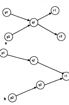
In addition to the consistency property, the collision problem between two transition paths also needs to be considered. If two transition paths mk and ml
have more than one common corner point, a collision occurs. Two collision examples are shown in Figs. 3a and b. Because we assume that each corner point belongs to a transition path, a collision is often a hint that some ambiguous matches occur. Thus, if two nearby transition paths mk and m, collide, these paths would not be consistent pairs. In this situation, we set u(mk, m,) = 0. On the other hand, mk and m, form a consistent pair and are denoted as u(mk, m,) = 1. In this case we say that mk and m, support each other.
The procedure to modify the initial probabilities by using the consistency property is formulated as follows. Let p$mj) denote the refined probability after the rth iteration. The new probability p,Y1(mj) should tend to be increased when some transition paths near corner point ci supporting mj are found. The degree which the transition path m, of cj reinforces pi(mk) should be related to the estimated likelihood that m, is correct. To compute the new probability pifl(mk)
for all transition paths mk in Mi, we examine each node in the area surrounding ci, but not including ci. That is,
dtrnk) = c c where k = 1,2 ,..., #(Mi). (11)
cj near ci m, in Mj
218 LEE AND DENG
a
FIG. 3. Path collision: (a) Case 1; (b) Case 2.
This quantity is zero if and only if there is no corner point surrounding ci which has possible transition paths supporting mk. From Eq. (5) we know that the radius
R determines the searching area. For an isolated corner point located in a large homogeneous region, any point in the window with radius R may not exist. A larger radius R would solve this problem but it would result in higher error rate. In this paper we change the window size to solve this problem. If an isolated point has no supporting corner point in the window with radius R, the radius of the searching window will be increased until several corners (say, five) are found.
According to qi, the probabilities of transition paths in Mi are updated by the formula
$“(mj) =p;(mj) X (A + B X &(mj)), j = 1,2,..., #wfi)T (12)
and
&+‘(+d = PT(+J,
(13)where the parameters A and B designate the delay rate and convergence rate, respectively. They are dependent on each other. In our experiments, A is set to 0.3 and B is set to 3. These two values are selected to reflect properly the effects of the pseudopath and supporting paths.
THREE-FRAME CORNER MATCHING 219
Finally, we normalize B’s to obtain new probabilities,
mk in M,
This procedure is repeated until the probabilities reach a steady state. Those corners in a transition path whose probability is greater than a threshold (about 0.8) are considered to be matched. If there is a collision between two transition paths, the path with the lower probability will be removed.
4. SEGMENTATION
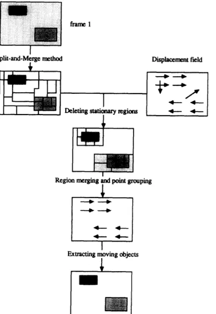
In this section, we propose a segmentation process which utilizes both motion and intensity information to extract multiple moving objects with translation, rotation, and scaling. The flow diagram is given in Fig. 4. First, each frame is segmented into small regions by using the split-and-merge method [35] based upon intensity information. Then the stationary regions which contain no matched corner points are removed. Second, we determine whether or not the motion has a scale change by searching a point called focus of expansion (FOE). If it is found, the displacement vectors would be processed based upon the feature of FOE. Otherwise, the motion displacement vectors would be processed by using the region-merge method. That is, these nearby corners of adjacent regions with similar displacement vectors are grouped together, and the regions of the same group are merged. The ungrouped points are removed. Finally, the regions of moving objects are labeled and extracted.
4.1. Images Segmentation and Stationary Region Deletion
If an image contains several moving objects with similar motion, only velocity information is not enough to extract these moving objects. The objects should be detected by using the contrast information. Therefore, we use the contrast infor- mation to roughly separate the regions of moving objects by the split-and-merge algorithm and then utilize the velocity information to refine the segmentation.
Because the velocity information is too sparse, sometimes it is difficult to cover the regions of moving objects completely. Larger regions would be helpful to reduce the impact due to the sparse velocity information. Thus, a strict condition is given during the region-split stage and a loose condition is given during the region-merge stage.
After segmenting each frame by using the split-and-merge method, we delete stationary regions. Assume that a given frame is partitioned into m regions. Let
R = {ri, i = 1,2,. . . , n) denote the set of regions and P = {J+, 1,2,. . . , n) repre- sent the set of the matched corner points. Each pi contains a list of three coordinates of the corner points and two displacement vectors di, and di, of the transition path.
It seems easy to delete a stationary region just by checking whether it contains a matched point. Sometimes it is unsatisfactory because some regions of moving objects contain no matched points. Also because these matched points are not error free, they would result in redundant regions. Furthermore, it is difficult to
220 LEE AND DENG
Split-and-M&e method
Region merging p point grouping
FIG. 4. Flow diagram of the segmentation process.
decide to which regions these matched points should be assigned because these points are located on the boundary between two or more regions.
Often background regions have large areas and some matched points are located on the boundary between regions of background and moving objects. If a matched point is assigned to a background region, the region will be incorrectly considered as belonging to a moving object. To avoid such an error, we assign this matched point to the region with a smaller area. This rule may fail for textured background, which would be partitioned into several small regions. These points should be reassigned based on other criteria. Some regions of moving objects may still
THREE-FRAME CORNER MATCHING 221 contain no matched points. They are reserved by using the heuristic that most of their surrounding regions have matched points.
4.2. Region-Merge
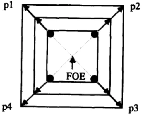
When either an object or the sensor moves in the depth-direction (i.e., the z-axis), the object projections will have scale change. This would cause all displace-
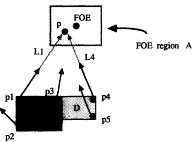
ment vectors flowing toward or away from a single point in the image plane, FOE. In Fig. 5 the displacement vectors on the moving square are flowing away from the point FOE.
For the object extraction, the algorithm begins with the search of the FOES to determine whether a scale change occurs. If an FOE is found, we can use the FOE to group the matched points. The regions with the same group of points will be merged together. The process is repeated until no more points can be grouped and no more regions can be merged.
Searching for the FOES, we first find all the intersection points of any two lines of the displacement vectors. Here, each line is found by minimizing the sum of square errors between the three corner points of a transition path and the fitted line segment. For any point p of the image plane, we count the number of intersection points. If we can find a high peak in the map of the intersection points, the peak is taken as an FOE. If an FOE is found, we say that there is a scale change. In order to detect the peak easily, we sharpen the peaks of the histogram by applying a local maximum filter. The number of intersection points in a given window is added to the point which is the local maximum and is set as zero. The region-merge procedure to extract the object regions with scale change is depicted formally as follows: Let A designate the region with an FOE. Let Li denote the approximation line of transition path mi associated with matched point ci. A region with no matched point is merged with any one of its surrounding regions. Assume that the matched point ci is located in region ri, point cj in region rj, and region ri is adjacent to region rj. If the intersection point of the two approximation lines Li and Lj, associated with ri and rj, respectively, are located in region A, then the two points are grouped and the two regions are merged together. We repeat this process for any pair of points in adjacent regions. When
Pl
K1
P2
P3
FIG. 5. Matching results of three consecutive frames. The displacement vectors on the moving square are flowing away from the FOE.
222 LEE AND DENG
FOE region A
P2
FIG. 6. Region-merge for the object motion with scaling.
the process terminates, there are some matched points still are not grouped. They are either due to error matches or due to object motion without scaling. These ungrouped points will be processed later.
We demonstrate the region-merge procedure by an example shown in Fig. 6. Here, region C contains three matched points pr, pz, and p3; region D contains two matched points p4 and pS. The intersection point of the two approximation lines Ll and L2 with respect to points p1 and p4 is located in region A, where the FOE is located. Thus, the two points are grouped together and two associated adjacent regions C and D are merged together. We repeat this process for any pair of points in regions C and D. The point p2 may be an error matched point.
Assume that there is no pure rotation. For the object motion without scaling, the motion should be pure translation. A region-merge procedure which is directly based on the similarity of the velocity vectors can be used to group matched points. That is, the points of adjacent regions would be grouped together if they have similar velocity vectors and the corresponding adjacent regions would also be merged together. We repeat this region-merge procedure until no more points can be grouped and no more regions can be merged.
4.3. Extracting Regions of Moving Objects
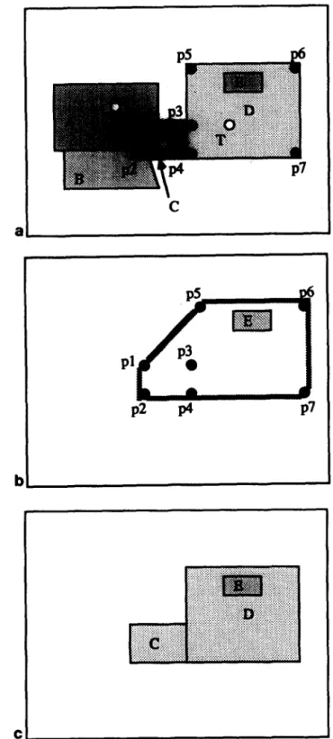
Assume that there are N groups of matched points corresponding to N moving objects in the frame after region merging. Because the corner points are sparse, some regions of a moving object may contain no matched point. These regions should be assigned to some moving objects. We determine whether region rj which has no matched point belongs to group gj by checking if the centroid tj(X, y) of r,
locates in the convex hull of group gj. If it does, region ri will be assigned to group g,. Otherwise, it will be removed. These removed regions are often the stationary background regions.
In Fig. 7a, all black circles represent the matched points belonging to the same group g,, regions A and B are background regions, regions C and D are object regions, and region E is an object region but it has no matched point. The region
THREE-FRAME CORNER MATCHING
223
C
I
al
P2
p4
P7
.Ib
cl
FIG. 7. Extracting regions of moving objects: (a) object regions and matched points; (b) the convex ~111; (c) final result.
224 LEE AND DENG
FIG. 8. Results of corner detection after deleting edge points, shadow points, and noise: (a) ar the candidate comer points; Cc) the results after deleting the points with the curvatures greater 150”; (d) the result after deleting the points whose differences are less than 21.
Id (b) than
THREE-FRAME CORNER MATCHING 225
226 LEE AND DENG
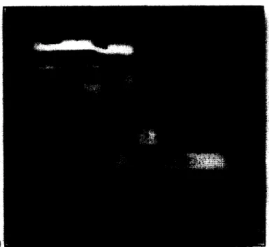
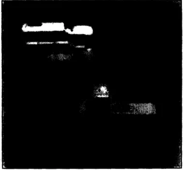
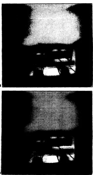
FIG. 9. Results of the three-frame matching method for the motion with scaling. Parameters: R = 20, p = 20, 6 = 0.2, and Y = 30; (a)-(d) iterations 0, 3, 6, and 12.
THREE-FRAME CORNER MATCHING 227
LEE AND DENG
FIG. 10. Results of the three-frame matching method for the motion with translation and rotation
THREE-FRAME CORNER MATCHING 229
TTT
I%. 11. Results of the segmentation for the motion with scaling: (a) the test images with detected comer Points; (b) the aPProximation lines; k> the histogram of the intersection points; (d) results after the split-and-merge method; k) the regions after deleting stationary regions; (f) the refined transition paths; (gl the final results.
THREE-FRAME CORNER MATCHING 231 . ..- . . . . . . *- . . . . . . . . . . . . . . . . e . . . . *p ** . . a, . . -.. . . . . . . ‘:. . . . . FIGURE 11 -Continued
232 LEE AND DENG
THREE-FRAME CORNER MATCHING
233
FIGURE 11 -Continued
hull of the group g,. However, regions A and B should be removed because their centroids are not located in the convex hull of the group g,. Finally, regions C,
D,
and
E,
which are labeled the same, are merged together, as shown in Fig. 7c.5. EXPERIMENTAL RESULTS
Our experimental results are intended to illustrate the three topics addressed in this paper. First, we demonstrate the ability of the two-stage corner detector.
Figures 8a and b show the corner points extracted by the Moravec interest operator. These candidate points are marked with a small cross. Figure 8c shows the results after deleting the edge points with curvature greater than 150”. Figure 8d shows the result after removing these redundant points in Fig. 8b.
Second, we illustrate the results of the three-frame matching procedure by analyzing two scenes with two different motion types as follows. The first scene includes a toy car with a pure translation of the sensor in the z-direction. Figures 9a-d show the results of the three-frame matching procedure after 0, 3, 6, and 12
iterations, respectively. Each black line segment denotes a possible transition path. The parameters in (5), (61, (7), and (10) are given as follows:
R = 20, p = 20,
6 = 0.2, and Y = 30. They are dependent on the sampling rate and object motion speed. We select these values by experimenting on some image sequences. From Fig. 9d, we note that most transition paths are flowing towards the FOE. The transition paths which are not flowing towards the FOE are removed by checking its orientation.
The second scene illustrates that two toy cars move from the right-hand side of image plane to the left-hand side and two cars remain stationary. The motion types
234 LEE AND DENG
Ftc. 12. Results of the segmentation for multiple objects with translation and rotation: (a) results after the split-and-merge method; (b) the reserved regions after deleting stationary regions; Cc) the refined transition paths; (d) the final results.
THREE-FRAME CORNER MATCHING 235
236
LEE AND DENGin this scene include translation and rotation. Because we take these images in the top view, there is no scale change. Figures lOa-d show the results after 0,3,6, and 12 iterations, respectively. The parameters are given as follows:
R = 20, p = 12,
6 = 0.18, and v = 32. There are two error transition paths on the upper left car which is stationary. These error paths can be removed by giving smaller parameters p and 6. But this will also remove some correct transition paths, which are often
isolated points located in a large homogeneous region.
Third, we show the performance of the proposed segmentation procedure applied to the matching results. The scaling case will be discussed first. The testing image with detected corner points is shown in Fig. lla. The approximation lines of the transition paths are presented in Fig. llb. The histogram of the intersection points is depicted in Fig. llc. The highest peak (116,128) of the histogram is found by using a local maximum filter with a 7 x 7 window. This peak would be taken as
the FOE. Then we segment Fig. lla by using the split-and-merge method. The result is shown in Fig. lld. After we delete some regions which contain no transition paths, the surviving regions are shown in Fig. lle, where a white cross represents a matched point. After we group these transition paths, Fig. llf gives the refined transition paths following the grouping. The final result of the segmen- tation is shown in Fig. llg.
Figures 12a-d show the results of another scene. In these figures we find two error transition paths on the upper left toy car. This would result in some redundant regions for segmentation, because the error matched points induce a larger convex hull than the original shape of the car. The refined transition paths are shown in Fig. 12c, and the redundant regions can be seen in Fig. 12d.
6. SUMMARY
Computation and interpretation of the optical flow field is an important task for dynamic scene analysis. The conventional approaches only used two frames to solve the problem. These two-frame methods usually under-utilize the time-flow information available to them. In this paper, we propose a three-frame matching method to compute the displacement field in three consecutive frames. We make better use of both velocity and contrast information to segment the displacement field.
The two-stage corner detector selects some candidate corner points by using the Moravec interest operator in the first stage. In the second stage, the 2-means clustering algorithm is adopted to analyze the neighboring regions of an interest point and then determine the real comer point. The advantages of our method are that: (1) it can remove noise and shadow points, (2) it can tolerate the distortion due to different 3D motion, (3) it can calculate the curvatures of the comers accurately, and (4) it is more precise than the Moravec interest operator.
The three-frame matching method utilizes the smoothness constraint of motion to find the candidate transition paths and delete some impossible transition paths. A relaxation labeling method based on the consistency property is used to determine the correct transitions. In general, the three-frame method has many advantages. First, it is satisfactory for different types of motion, including transla- tion, rotation, and scaling. Second, it is also not sensitive to noise and distortions due to 3D motion. Third, it is more effective than two-frame matching methods.
THREE-FRAME CORNER MATCHING 237 The success of the three-frame matching method comes from its ability to integrate effectively time-flow information and 3D spatial continuity constraints.
The segmentation method integrates both velocity information and contrast information to partition the displacement field. Particularly, we utilize the charac- teristic of FOES to segment the displacement field generated by a scaling motion. Also under the assumption of smooth motion, we make use of the similarity of the velocity vectors to segment the displacement field generated by object motion with translation and rotation. Besides, our system can remove error displacement vectors after the displacement vectors are grouped. One of the disadvantages of our system is that the velocity information generated by the three-frame matching method is sparse. It would probably miss some regions of the moving objects.
REFERENCES
1. T. S. Huang, Determining three-dimensional motion and structure from two perspective views, in
Handbook of Pattern Recognition and Image Processing (T. Y. Yong and K. S. Fu, Eds.), pp. 344-353, Academic Press, New York, 1986.
2. T. S. Huang, Image Sequence Analysis, Springer-Verlag, Berlin/New York, 1981.
3. A. Mitiche and J. K. Aggarwal, A computational analysis of time-varying images, in Handbook of
Pattern Recognition and Image Processing (T. Y. Yong and K. S. Fu, Eds.1, pp. 311-332, Academic Press, New York, 1986.
4. H.-H. Nagel, Analysis techniques for image sequences, in Proceedings, ZJCPR-78, Kyoto, Japan,
Nov. 1978, pp. 356-374.
5. A. Rosenfeld and A. C. Kak, Digital Picture Processing, 2nd ed., Academic Press, New York, 1982. 6. A. Rosenfeld and G. J. VanderBrug, Coarse-fine template matching, IEEE Trans. Systems Man
Cybernet. SMC-7, 1977, 104-107.
7. A. Goshtasby, M. Herman, and T. Kanade, Incremental reconstruction of 3D scenes from multiple, complex images, Artif. Zntell. 30, 1986, 289-341.
8. B. K. P. Horn and B. G. Schunk, Determining optical flow, Artif. Zntell. 17, 1983, 185-203. 9. W. B. Thompson and S. T. Barnard, Lower-level estimation and interpretation of visual motion,
Computer 14, 1981, 20-28.
10. S. T. Barnard and W. B. Thompson, Disparity analysis of images, IEEE Trans. Pattern Anal. Mach. Zntell. PAMI-2, 1980, 333-340.
11. C. Y. Wang, H. Sun, S. Yada, and A. Rosenfeld, Some experiments in relaxation image matching using corner features, Pattern Recognit. 16, 1983, 161-182.
12. J.-Q. Fang and T. S. Huang, Some experiments on estimating the 3D motion parameters of a rigid body from two consecutive image frames, IEEE Trans. Pattern Anal. Mach. Zntell. PAMI-6, 1984, 545-554.
13. Y. Obta and T. Kanade, Stereo by intra- and inter-scanline search using dynamic programming,
IEEE Trans. Pattern Anal. Mach. Zntell. PAMI-7, 1985, 139-154.
14. G. Medioni and R. Nevatia, Segment-based stereo matching, Comput. V&ion Graphics Image Process. 31, 1985, 2-18.
15. K. Price and R. Reddy, Matching segments of images, IEEE Trans. Pattern Anal. Mach. Zntell.
PAMI-1, 1979, 110-116.
16. J. L. Potter, Scene segmentation using motion information, Comput. Graphics Image Process, 6,
1977, 558-581.
17. W. B. Thompson, Combining motion and contrast for segmentation, IEEE Trans. Pattern Anal. Mach. Zntell. PAMI-2, 1980, 543-549.
18. C. L. Fennema and W. B. Thompson, Velocity determination in scenes containing several moving objects, Comput. Vision Graphics Image Process. 9, 1979, 301-315.
19. G. Adiv, Determining three-dimensional motion and structure from optical flow generated by several moving objects, IEEE Trans. Pattern Anal. Mach. Zntell. PAMI-7, 1985, 384-401. 20. J. S. Lappin, J. F. Doner, and B. L. Kottas, Minimal conditions for the visual detection of structure
and motion in three dimensions, Science 209, 1980, 717-719.
238 LEE AND DENG
22. H. Shariat and K. E. Price, How to use more than two frames to estimate motion, in Procee&zgs,
IEEE Workshop on Motion: Representation and Analysis, Charleston, South Carolina, 1986, pp. 119-124.
23. I. K. Sethi and R. Jain, Establishing correspondence of non-rigid objects using smoothness of motion, in Proceedings, Int. Joint Conf. Pattern Recognition, 1984, pp. 83-87.
24. M. Jensen, Tracking three dimensional moving light displays, in Proceedings, Workshop on Motion: Representation and Control, Toronto, 1983, pp. 66-70.
25. I. K. Sethi and R. Jain, Finding trajectories of feature points in a monocular image sequence, in
Proceedings, Int. Joint Conf. Pattern Recognition, 1985, pp. 106-111.
26. B. L. Yen and T. S. Huang, Determining 3-D motion and structure of a rigid body using the spherical projection, Comput. Vision Graphics Image Process, 21, 1983, 21-32.
27. S. L. Horowitz and T. Pavlidis, A graph-theoretic approach to picture processing, Compur. Graphics Image Process. 7, 1978, 282-291.
28. E. M. Riseman and M. A. Arbib, Computational techniques in the visual segmentation of static scenes, Comput. Graphics Image Process. 6, 1977, 221-276.
29. M. L. Braunstein, Depth Perception through Motion, Academic Press, New York, 1976.
30. H. H. Nagel, Formation of an object concept by analysis of systematic time variations in the optically perceptible environment, Comput. Ksion Graphics Image Process. 7, 1978, 149-194. 31. R. Jain, W. N. Martin, and J. K. Aggarwal, Segmentation through the detection of changes due to
motion, Comput. Vision Graphics Image Process. 11, 1979, 13-34.
32. R. Jain, Extraction of motion information from peripheral process, IEEE Trans. Pattern Anal. Mach. Intell. PAMIJ, 1981, 489-503.
33. J.-Q. Fang and T. S. Huang, Solving three-dimensional small rotation motion equations: Unique- ness, algorithms, and numerical results, Comput. Vision Graphics Image Process. 26, 1984,
183-206.
34. H. P. Moravec, Towards automatic visual obstacle avoidance, in Proceedings, 5th Int. Joint Conf. Artv. Intell., Cambridge, MA, 1977, p. 584.
35. L. Dreschler and H. H. Nagel, Volumetric model and 3D-trajectory of a moving car derived from monocular TV-frame sequences of a street scene, Comput. Vision Graphics Image Process. 20,
1982, 199-228.
36. L. Kitchen and A. Rosenfeld, Gray-level corner detection, Pattern Recognit. Lett. 1, 1982, 95-102. 37. P. H. Winston, Artificial Intelligence, 2nd ed., Addison-Wesley, Reading, MA, 1984.
38. P. A. Devijver and J. Kittler, Pattern Recognition-A Statistical Approach, Prentice-Hall, London, 1982.
39. A. Rosenfeld and E. Johnson, Angle detection on digital curves, IEEE Trans. Comput. 22, 1973.
![TraditionalMLCalgorithmsmainlytacklethebatchMLCproblem,wheretheinputdataarepresentedinabatch[24,28].Nevertheless,inmanyMLCapplicationssuchase-mailcategorization[22],multi-labelexamplesarriveasastream.Onlineanalysisistherefore dimensionreducermotivatedbyma](data:image/gif;base64,R0lGODlhAQABAIAAAP///wAAACH5BAEAAAAALAAAAAABAAEAAAICRAEAOw==)