Applications of multidirectional asymmetrical
microlens-array light-control films on reflective
liquid-crystal displays for image quality enhancement
Yi-Pai Huang, Han-Ping David Shieh, and Shin-Tson Wu
The multidirectional asymmetrical microlens-array light-control film 共MAMA-LCF兲 is developed for enhancing the image brightness and contrast ratio of various reflective liquid-crystal displays. By use of index-matching material, the interface reflection is greatly reduced. Through optimized designs, the surface-scattering effect is also suppressed; thus the contrast ratio is much enhanced. From experi-mental results, the MAMA-LCF leads to a⬃1.5⫻ gain in brightness over the MgO standard white and a 15:1 contrast ratio for the reflective color super-twist nematic liquid-crystal display, 2.8⫻ MgO and a 23:1 contrast ratio for the polymer-dispersed liquid-crystal, and 2.8⫻ MgO and a 13:1 contrast ratio for the cholesteric liquid-crystal display. Potential applications of this low-cost plastic thin film for reflec-tive liquid-crystal displays are foreseeable. © 2004 Optical Society of America
OCIS code: 230.3720.
1. Introduction
Reflective liquid-crystal displays1共LCDs兲 are widely
used in portable personal digital assistants and mo-bile communications. Varieties of new applications, such as super-twist nematic LCDs2共STN-LCDs兲 for
mobile phones, polymer-dispersed liquid crystals3
共PDLCs兲 for smart cards, and cholesteric LCDs4,5
共Ch-LCDs兲 for electronic books, have been consid-ered. In these applications, low power consumption, high brightness, high contrast ratios, and low cost are critical. However, most reflective LCDs still suffer from inadequate brightness and contrast ratio共CR兲. Many methods, for example, laminating front-scattering film6on color STN-LCDs, building
rough-surface reflectors 共bump reflectors兲7 on the bottom
substrates of PDLCs, and using single-surface rubbed cells for Ch-LCDs, have been proposed for improving the brightness and the CR. Our group has developed an asymmetrical microlens-array
light-control film8共AMA-LCF兲 to enhance the brightness of
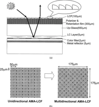
reflective LCDs. Figure 1共a兲 depicts the device structure and working principle of the AMA-LCF. Later the concept of the AMA-LCF was extended to multidirectional asymmetrical microlens-array light-control film9共MAMA-LCF兲 to widen the display
view-ing angle and brightness. As illustrated in Fig. 1共b兲, by arrangement of microlenses into various orienta-tions, multiple ambient illuminations can be effec-tively collected and redirected. As a result, the viewing angle is widened; brightness and the CR are enhanced. Additionally, simple fabrication and low cost are the other advantages of the MAMA-LCF. In this paper the performances of MAMA-LCF on three kinds of reflective LCD, color STN-LCD, PDLC, and Ch-LCD, are demonstrated. Through optimized de-signs, the image quality of these displays can be sig-nificantly improved.
2. Reflective Liquid-Crystal Displays with MAMA-LCF
MAMA-LCF with a 100% fill factor was designed for a typical ambient environment to significantly im-prove the image quality of reflective LCDs. For avoiding color dispersion, the MAMA-LCF structure was modeled as multiple slit gratings9and was
con-sidered in terms of diffraction angle and intensity. By comparing the intensity of different diffraction orders, we can determine which order is relevant and derive the dispersion angle. Accordingly, the hu-man pupil and the viewing distance determine the Y.-P. Huang and H.-P. D. Shieh共[email protected]兲 are
with Institute of Electro-Optical Engineering, National Chiao Tung University, Hsinchu 30010, Taiwan. S.-T. Wu is with the School of Optics and the Center for Research and Education in Optics and Lasers, University of Central Florida, Orlando, Florida 32816.
Received 5 January 2004; revised manuscript received 23 March 2004; accepted 29 March 2004.
0003-6935兾04兾183656-08$15.00兾0 © 2004 Optical Society of America
minimum grating period of indistinguishable color dispersion that is taken into account in the design of MAMA-LCF.
Furthermore, in this design, the moire´ pattern,9
which might occur when periodic light-control film 共LCF兲 structures and periodic pixels of a color filter are superimposed, was also considered. The moire´ pattern can be prevented by one’s adopting a specific ratio of the periods of those two structures with a fixed angular difference. Then MAMA-LCF can be designed to have microlenses with multiple orienta-tions, in which each microlens has a different pitch and orientation. From the above calculations, an optimal size and arrangement of microlenses can be determined, so that the MAMA-LCF laminated onto a color STN-LCD can yield high brightness and good contrast without visible color dispersion or the moire´ pattern.
Additionally, index matching and surface scatter-ing should also be considered while the LCF is lam-inated onto a reflective LCD. From Fresnel’s equation and Snell’s law, the surface reflective ratio10
between two layers with different refractive indices for the S wave共TE兲 and P wave 共TM兲 can be respec-tively shown as Eqs.共1兲 and 共2兲:
Rs⫽ 兩rs兩2⫽ 兩共cos ⫺
冑
n2⫺ sin2兲兾共cos ⫹
冑
n2⫺ sin2兲兩2, (1)Rp⫽ 兩rp兩2⫽ ⫺兩共n2cos ⫹
冑
n2⫺ sin2兲兾共n2cos⫹
冑
n2⫺ sin2兲兩2. (2)Here n ⫽ nt兾ni is the relative refractive index of refraction of the refractive indices of the incident共ni兲
and the transmitted 共nt兲 media and is the light
incident angle. Therefore the total surface reflective ratio Rtotalis
Rtotal⫽
冑
共IisRs兲2⫹ 共IipRp兲2兾冑
共Iis兲2⫹ 共Iip兲2, (3)where Iisand Iipare the intensities of the incident S
and P waves, respectively. Assuming the incident light is unpolarized, then Iis ⫽ Iip. Consequently,
Rtotalcan be simplified to
Rtotal⫽
冑
共Rs兲2⫹ 共R
p兲
2兾
冑
2. (4)
For example, with the light illuminated from 30° on a plastic film of refractive index n⫽ 1.55, the total surface reflection is 5.15%. Compared with the 12.5% reflective light efficiency of a reflective LCD, as signified in Fig. 2, the surface reflection results in serious degradation to the CR. Additionally, the mi-crolens on MAMA-LCF was approximated by use of a four-step Fresnel lens instead of a traditional curva-ture lens. Therefore the edge of each step may scat-ter the incident light, which results in increased dark-state light leakage and a degraded CR. Thus several methods were proposed for laminating the LCF on three kinds of LCD, reflective color STN, PDLC, and cholesteric, to overcome the above-mentioned issues.
A. Reflective Color Super-Twist Nematic
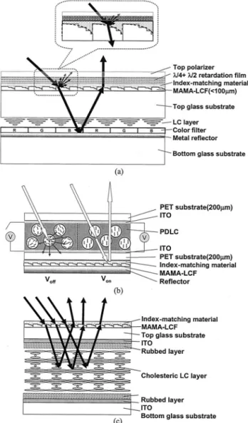
The designed patterns and system configuration of the MAMA-LCF on reflective color STN-LCDs are shown schematically in Figs. 1共b兲 and 3共a兲, respec-tively. In a reflective color STN-LCD, the pixel size is 210 m ⫻ 210 m, which covers more than 50 microlenses. Thus the moire´ patterns are not visi-ble because the designed structure and the pitch of the microlenses are much smaller than the pixel size. Moreover, coating an index-matching material on LCF and laminating it below the polarizer, as de-picted in Fig. 3共a兲, is found to greatly reduce the intensity of interface reflection and front-scattering light. As a result, MAMA-LCF that is laminated below the polarizer should be made of a low-birefringence material to avoid the color shift caused by the retardation effect.
Fig. 1. 共a兲 Panel configuration of a reflective display laminating a light-control film and共b兲 unidirectional AMA-LCF modified as a multidirectional AMA-LCF for collecting and redirecting multiple ambient illuminations. LC, liquid crystal; LCF, light-control film.
B. Reflective Polymer-Dispersed Liquid Crystal
MAMA-LCF is also applicable to the reflective PDLC developed for plastic smart cards. Usually, the MAMA-LCF is laminated on the top surface of the PDLC. Under such circumstances, the film modu-lates the reflected light from the interface of each layer and deteriorates the blackness of the dark state.
Thus the MAMA-LCF coated with an index-matching material is preferably laminated between the bottom substrate of the plastic PDLC panel and the alumi-num reflector with an index-matching material coated, as depicted in Fig. 3共b兲. Moreover, the plas-tic LCF is flexible and can be easily combined with the plastic PDLC displays.
C. Reflective Cholesteric Liquid-Crystal Display
The Ch-LCD is a candidate for electronic books be-cause of its low power consumption. For a conven-tional Ch-LCD to achieve a wide viewing angle, only the bottom substrate is rubbed, and the top plate has no rubbing. The liquid-crystal共LC兲 directors tilt to different angles. These slightly disordered choles-teric layers help to diffuse the reflected light to a wider viewing zone. The trade-off of this approach is that the maximum reflectivity is reduced to 35%. On the other hand, the two-surface rubbed cell ex-hibits a higher 共⬃50%兲 reflectivity except that its viewing angle is much narrower. Integrating a MAMA-LCF on the two-surface rubbed cell to widen the viewing angle while preserving high reflectivity will be more appealing for applications. As shown in Fig. 3共c兲, the MAMA-LCF helps to diffuse light to a larger angle. Moreover, coating an index-matching material on MAMA-LCF can reduce the interface re-flections. Benefitting from the LCF, the two-surface rubbed Ch-LCD is expected to exhibit a wide viewing angle and high reflectivity.
3. Experiments
A. Fabrication of MAMA-LCF
The asymmetrical microlens array is implemented with a binary Fresnel microlens structure because of its 100% fill factor and the simple fabrication of the asymmetrical microlens pattern. Furthermore, the binary Fresnel microlens is easily fabricated with standard semiconductor processes of photolithogra-phy and reactive ion etching on a Si wafer utilized as a substrate for making a father mold. Then the Si substrate is electroplated with a nickel layer to serve as a mother mold. Next, this Si-based structure is duplicated from the mother mold to a transparent plastic film, such as polyvinyl chloride and arton cy-clic olefin copolymers共arton-COCs兲, by stamp mold-ing. The arton-COC film is used for color STN to avoid the color shift because of its low birefringence. Fig. 3. Schematic plot of the system configuration of the
MAMA-LCF on the共a兲 reflective color STN-LCD, 共b兲 PDLC display, and 共c兲 two-surface rubbed Ch-LCD. PET, polyethylene terephthalate; ITO, indium tin oxide.
Table 1. Configuration of Test Panels
Code Name Type of Test Panel
Index-Matching-Material
Coating Laminated Position of LCF
Bare STN Color STN No Without LCF
STN-A Color STN No Above top polarizer
STN-B Color STN Yes Between top polarizer and top glass substrate
Bare PDLC PDLC No Without LCF
PDLC-A PDLC Yes Between bottom substrate and bottom reflector
Bare Ch-LCD Ch-LCD No Without LCF
An index-matching material, EGC1700共n ⫽ 1.38兲, is then spin coated on the surface of the plastic film to protect the microlens structure and reduce the sur-face scattering. From Eq.共4兲, the surface reflection of the MAMA-LCF共n ⫽ 1.55兲 coated with EGC1700 共n ⫽ 1.38兲 can be diminished to only 0.41%. Finally, the multidirectional LCF is laminated onto the re-flective LCD to realize control of the distribution of the reflected light. By use of these well-developed fabrication processes, a precise micro-optical struc-ture can be produced economically and reproducibly in large volume.
B. Liquid-Crystal-Display Parameters
The configurations and the parameters of the differ-ent LCDs laminated with MAMA-LCF are listed in Tables 1 and 2, respectively. Different focal lengths and the lens configuration of the microlens array can be designed with the optical software ASAP. The
light-control effect of MAMA-LCF can be optimized for each LCD depending on its specific needs. C. Evaluation of Morphological and Optical Properties We evaluated the light-control effect and the contrast improvement of LCF by laminating MAMA-LCF on the reflective color STN-LCD, reflective PDLC, and reflective Ch-LCD. To measure the re-flective brightness and CR, we fixed a single incident light at⫺30° as an ambient light and detected the reflected light by using Otsuka LCD evaluator 5100 at effective viewing angles from 0° to 40°. For eval-uating the effect of surface reflection, a conoscopic system, ELDIM EZContrast 160R, which can mea-sure a ⫾80° viewing cone, was used with a ⫺30° illumination.
4. Experimental Results
A. Surface Reflection of MAMA-LCF
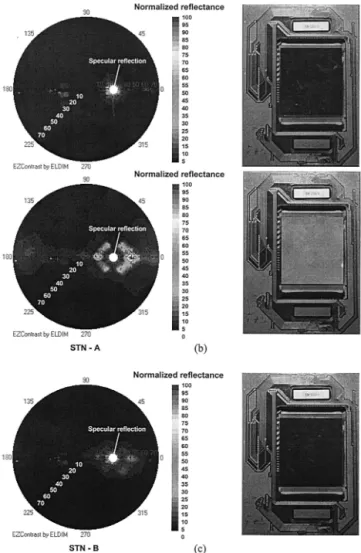
To observe the surface reflection induced by MAMA-LCF, we measured test panels of the reflective color STN laminated with MAMA-LCF. The test panels were in a dark state with a collimated light illumi-nated from ⫺30°; thus the specular reflection oc-curred at 30°, as the white spots shown in Fig. 4. The reflectivity of the panels were measured and
plot-ted in polar coordinates to reveal the effect of surface reflection. The measured results of the bare STN, STN-A, and STN-B are shown in the left part of Figs. 4共a兲–4共c兲, respectively, and the right part displays photographs of the dark-state images of the three test panels taken from normal viewing angles.
Obviously, both the measured result and the pho-tograph of the bare STN reveal that the panel can
Fig. 4. Measured reflectivity 共left part兲 and photographs 共right part兲 of the dark-state images of the 共a兲 bare STN, 共b兲 STN-A, and 共c兲 STN-B.
Table 2. Parameters of the Reflective Color STN, PDLC, and Ch-LCD Used
LC Mode Color STN PDLC Cholesteric
LCF 100m 100m 100m
Index-matching material EGC1700共3 m兲 EGC1700共3 m兲 EGC1700共3 m兲
Polarizer 200m None None
Retardation film 100m None None
Substrate Glass共0.6 mm兲 Plastic PET共0.1 m兲a Glass共0.7 mm兲
Indium tin oxide共m兲 0.1 0.1 0.1
LC cell gap共m兲 5 6 5
Color filter共m兲 2 None None
Rubbed layer Both sides共0.15 m兲 None Both sides共0.15 m兲
Reflector Metal reflector Metal reflector Cholesteric reflector
display a very dark image in the viewing region. However, from Fig. 4共b兲, the reflective light of the dark state of the STN-A has a noticeably crescent distribution because the LCF was not coated with an index-matching material; thus the interface reflec-tion efficiency was higher, to 5.15%. The interface reflective light was modified by the Fresnel lenses of the LCF and directed into the viewing region as the crescent distribution to increase the brightness in the dark state of the STN-A, as shown in the photograph in Fig. 4共b兲. Additionally, the edge of each step of the four-step Fresnel lenses causes surface scatter-ing, as the dark gray area shown in the polar plot of Fig. 4共b兲, which also degrades the image quality at a large viewing angle. By use of the configuration of the STN-B, in which MAMA-LCF was coated with an index-matching material共EGC1700, n ⫽ 1.38兲 to re-duce the interface reflection and laminated below the polarizer to decrease the surface scattering, the dark-ness of the panel was greatly improved, as shown in the photograph in Fig. 4共c兲.
MAMA-LCF coated with an index-matching mate-rial was also used for the PDLC and Ch-LCD; the measured dark-state reflectance polar plots of the two LCDs are shown in Figs. 5共a兲 and 5共b兲, respec-tively. These two devices are nonpolarized displays; thus the LCF for the PDLC was laminated between the bottom substrate and the reflector to decrease the surface scattering. The reflector of the Ch-LCD, however, is the LC cell itself. Therefore LCF can be added only to the top surface of the Ch-LCD; the interface reflection can be reduced by one’s coating the LCF with an index-matching material, yet the surface scattering is slightly visible while the dark-state image is displayed.
B. Image Improvement by MAMA-LCF
By one’s coating an index-matching material on the MAMA-LCF, the intensity of the surface reflection can be much reduced to improve the display quality of Fig. 5. Measured results of the dark-state reflectance of the共a兲
PDLC-A and共b兲 Ch-LCD-A. Fig. 6. Measured
共a兲 reflectivity and 共b兲 CR of the reflective color STN-LCD as a function of viewing angle under illumination from ⫺30°.
a dark-state image. Thus the new configurations of the three display panels, STN-B, PDLC-A, and Ch-LCD-A, were measured and compared with the bare test panels. The measured angular-dependent re-flectivity and CRs of the reflective color STN, PDLC, and cholesteric panels are shown in Figs. 6 – 8, re-spectively. For a collimated illumination from ⫺30°, the specular reflection occurs at 30°. At this angle, although the reflectivity is high, the CR is poor. Adding a MAMA-LCF not only shifts the peak reflectance of the color STN panel from 30° to 15° but also enhances reflectivity by ⬃1.5⫻ over the MgO standard white关solid curve, Fig. 6共a兲兴. Because the LCF was coated with an index-matching material, EGC1700 共n ⫽ 1.38兲, and laminated below the top polarizer, the surface reflection is reduced and the CR is increased, as shown by the solid curve in Fig. 6共b兲, where the CR is higher than 10 within viewing angles of 0° to 18° with a peak value of 15. Therefore MAMA-LCF, covered by EGC1700 and adhesive
be-low the top polarizer, can provide an image with a good CR and high brightness in the viewing region.
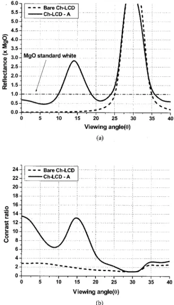
Similarly, the reflectance profile of a PDLC sample also reveals that laminating the LCF on the bottom side of the reflective PDLC共PDLC-A兲 yields a very high brightness共2.8⫻ of MgO兲 with a maximum CR ⬃23:1 in the viewing angle of 14°, as shown in Figs. 7共a兲 and 7共b兲. In the Ch-LCD experiments, two cells using E48 LCs doped with ZLI-811 chiral agent, which has a peak wavelength at green, were used. The back side of each cell was painted black for im-proving the CR. The MAMA-LCF was coated with EGC1700 and laminated on the top surface of the Ch-LCD cell. Figure 8 plots the measured reflec-tance and CRs of the two-surface buffed Ch-LCDs with and without MAMA-LCF. The Ch-LCD with LCF共solid curve兲 shows a higher reflectance in the 0°–20° viewing zone. At 14°, the LCF enhances the display brightness by a factor of 2.8 to that of MgO standard white. Additionally, the CR of the Ch-Fig. 7. Measured共a兲 reflectivity and 共b兲 CR of the reflective PDLC
as a function of viewing angle under illumination from⫺30°.
Fig. 8. Measured共a兲 reflectivity and 共b兲 CR of the reflective Ch-LCD as a function of viewing angle under illumination from⫺30°.
LCD with MAMA-LCF, depicted as the solid curve in Fig. 8共b兲, is increased to 13 at 14°.
Photographs of displayed images in which MAMA-LCF was used on a color STN-LCD, PDLC, and Ch-LCD, taken under ambient conditions, are shown in Figs. 9共a兲–9共c兲, respectively. In a comparison, Fig. 9共a兲 is the photograph of the STN-LCD with MAMA-LCF共left兲 and an 80% haze diffuser 共right兲, which is commonly used to enhance the brightness of mobile displays. The photographs of a PDLC with MAMA-LCF and a bare PDLC are shown in Fig. 9共b兲. Ad-ditionally, Fig. 9共c兲 displays the two-surface buffed Ch-LCD with and without MAMA-LCF and the pho-tographs of MAMA-LCF used on conventional nu-merical twist nematic panels with injected Ch-LC material, which reflected green and orange colors. The high image quality by the MAMA-LCF on the three different LCDs is clearly demonstrated.
5. Discussion and Expectation
Many image-enhanced components for reflective dis-plays have been proposed and used. These compo-nents are generally divided into two categories: diffusive 共bump reflector7 and diffuser6兲 and
collec-tive共MAMA-LCF,9 microslant reflector,11and
holo-graphic film12兲. The comparison of their respective
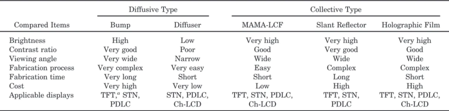
performances among MAMA-LCF and other compo-nents is listed in Table 3. The bump reflector can provide the best image quality with high brightness, a good CR, and a wide viewing angle, yet it requires a complex fabrication process that results in a high cost. A diffuser has the lowest price; nevertheless, its image quality is not as good as other approaches. MAMA-LCF, the slant reflector, and holographic film can display almost the same image quality. MAMA-LCF, however, utilizes a well-developed semiconduc-tor process and stamp molding to reduce the fabrication cycle. Plastic film is used as the sub-strate; thus the material cost is low. Furthermore, the filmlike component can be laminated on most kinds of reflective display, which extends the compet-itiveness of MAMA-LCF.
The modified MAMA-LCFs have been demon-strated to increase the image quality of reflection-type display. The lens structure of MAMA-LCF can collect and redirect the reflected light into a lower Fig. 9. Sample photographs of the共a兲 color STN-LCD, 共b兲 PDLC,
and共c兲 Ch-LCD. The displays with MAMA-LCF clearly show much better image quality. TN, twist nematic.
Table 3. Comparison of Conventional Image-Enhanced Components Used for Reflective Displays
Compared Items
Diffusive Type Collective Type
Bump Diffuser MAMA-LCF Slant Reflector Holographic Film
Brightness High Low Very high Very high Very high
Contrast ratio Very good Poor Good Very good Good
Viewing angle Very wide Narrow Wide Wide Wide
Fabrication process Very complex Very easy Easy Complex Complex
Fabrication time Very long Short Short Long Short
Cost Very high Very low Low High High
Applicable displays TFT,aSTN, PDLC STN, PDLC, Ch-LCD TFT, STN, PDLC, Ch-LCD TFT, STN, PDLC TFT, STN, PDLC, Ch-LCD aTFT, thin-film transistor.
viewing region, resulting in a high-brightness image. Nevertheless, such a lens structure also focuses the reflected light to a limited viewing angle, as shown experimentally. To further extend the application for different kinds of reflective LCD, one can also design the LCF by using grating structures that widen the viewing angle, improve the brightness uni-formity, and keep the reflectance to approximately 1⫻ MgO.
6. Conclusions
Conventional reflective LCDs are of low brightness and poor contrast ratio. The use of MAMA-LCF ef-fectively enhances the display brightness and con-trast of reflective color STN 共1.5⫻ MgO, CR ⬃15兲, PDLC共2.8⫻ MgO, CR ⬃23兲, and Ch-LCD 共2.8⫻ MgO, CR⬃13兲 under ambient light conditions. By use of an optimized design, the dispersion, moire´ patterns, and parallax, which may be caused by the microcom-ponents, are all invisible. The surface scattering of MAMA-LCF can also be reduced by coating an index-matching material 共EGC1700, n ⫽ 1.38兲. The MAMA-LCF can be easily fabricated by semiconduc-tor processes and injection–stamp molding. By use of these well-developed fabrication processes, the de-signed microlens structure on a thin transparent plastic substrate can be produced economically and reproducibly in large volume.
This research was partially supported by the Na-tional Science Council, Taiwan, under contract NSC89-2215-E009-082, and Wintek Corporation. We express our appreciation to F. J. Ko, AU Optron-ics Corporation, for valuable advice, Fredric Vicentini of Alien Technology, H. W. Ren and X. Y. Zhu of the University of Central Florida, J. Reineix and C. Vota of the Universite´ Paris Sud Center d’Orsay, K. H. Liu of the Electronics Research and Service Organization of the Industrial Technology Research Institute, and Y. C. Wu, J. Wang, and J. J. Chen of Wintek Corpo-ration for valuable discussion and technical support.
References
1. S. T. Wu and D. K. Yang, “Overview of reflective displays,” in Reflective Liquid Crystal Displays 共Wiley, Chichester, UK, 2001兲, pp. 1–31.
2. I. Fukuda, E. Sakai, Y. Kotani, M. Kitamura, and T. Uchida, “A new achromatic reflective STN-LCD with one polarizer and one retardation film,” J. Soc. Inf. Disp. 3, 83– 87共1995兲. 3. H. J. Cornelissen, J. H. M. Neijzen, F. A. M. A. Paulissen, and
J. M. Schlangen, “Reflective direct-view LCDs using polymer dispersed liquid crystal共PDLC兲 and dielectric reflectors,” in Proceedings of the Seventeenth International Display Research Conference共Society for Information Display, San Jose, Calif., 1997兲, pp. 144–147.
4. D. K. Yang, L. C. Chien, and J. W. Doane, “Cholesteric liquid-crystal polymer– gel dispersions: reflective display applica-tions,” in Proceedings of the Society for Information Display 共Society for Information Display, San Jose, Calif., 1992兲, pp. 759 –761.
5. Z. J. Lu, J. L. West, X. Y. Huang, D. K. Yang, and J. W. Doane, “Surface-modified reflective cholesteric displays,” in Proceed-ings of the Society for Information Display共Society for Infor-mation Display, San Jose, Calif., 1995兲, pp. 172–175. 6. T. Uchida, T. Nakayama, T. Miyashita, and T. Ishinaba, “A
novel reflective LCD for high resolution color display,” in Pro-ceedings of the Fifteenth International Display Research Con-ference 共Society for Information Display, San Jose, Calif., 1995兲, pp. 599–602.
7. Y. Itoh, S. Fujiwara, N. Kimura, S. Mizushima, F. Funada, and M. Hijikigawa, “Influence of rough surface on the optical char-acteristics of reflective LCD with a polarizer,” in Proceedings of the Society for Information Display共Society for Information Display, San Jose, Calif., 1998兲, pp. 221–224.
8. F. J. Ko and H. P. D. Shieh, “Brightness and contrast enhance-ment of reflective liquid crystal displays by microlens array light control film,” Jpn. J. Appl. Phys. 39, 2647–2650共2000兲. 9. Y. P. Huang, J. J. Chen, F. J. Ko, and H. P. D. Shieh,
“Multi-directional asymmetrical microlens array light control film for improved image in reflective color liquid crystal displays,” Jpn. J. Appl. Phys. 41, 646 – 651共2002兲.
10. G. R. Fowles, “The vectorial nature of light,” in Introduction to Modern Optics, 2nd ed.共Holt, Rinehart & Winston, New York, 1975兲, pp. 40–46.
11. G. T. Valliath, Z. A. Coleman, J. L. Schindler, R. Polak, R. Akins, and K. Jelley, “Design of hologram for brightness en-hancement in color LCDs,” in Proceedings of the Society for Information Display 共Society for Information Display, San Jose, Calif., 1998兲, pp. 1139–1143.
12. C. J. Wen, D. L. Ting, C. Y. Chen, L. S. Chuang, and C. C. Chang, “Optical properties of reflective LCD with diffusive micro slant reflectors共DMSR兲,” in Proceedings of the Society for Information Display共Society for Information Display, San Jose, Calif., 2000兲, pp. 526–529.