Design and analysis of electrically
calibrated tympanic thermometers
Mang Ou-Yang, Jin-Shown Shie, and Chyi Tsao
A new tympanic thermometer is analyzed and tested experimentally. An electrically calibrated pyro-electric detector of special configuration is employed to determine a person’s body temperature. An energy-storage, power-supply-isolated capacitor is used as the electrical heating reference. The new thermometer design has an accuracy within60.1 °C with a 90% confidence and is immune to ambient temperature, detector aging, and parameter variations. An equivalent-circuit model is established in the analysis to account for the heat exchanges among the tympanum, the surroundings, and the detector as well as for the electrothermal behavior of the detector. The model provides effective simulation of the thermometer with PSPICE. Critical parameters governing the accuracy and the limitation of the tympanic thermometer are also pointed out by the simulation. © 1998 Optical Society of America
OCIS codes: 040.3060, 120.6780, 120.5630, 170.3890.
1. Introduction
The temperature, the heart rate, the blood pressure, and the respiratory rate of human beings are the four traditional cardinal vital signs from a medical point of view. Physiologically, one’s temperature repre-sents the mixed body heat generated in one’s meta-bolically active organs and subcutaneous tissues. Medically, the internal human-body temperature is called the core temperature, which is normally main-tained within 376 0.75 °C ~Ref. 1! by blood, the heat transport medium. Clinically, medical profession-als have long been interested in accurately monitor-ing the core temperature of patients, primarily because temperature measurement is the first step in understanding the patient’s condition, and the diag-nosis or the treatment of many diseases depends on the accuracy of the core-temperature reading. So far, various ways of measuring core temperature have been developed, including mercury and elec-tronic thermometers, a probe with an esophagal stethoscope, bladder, and pulmonary artery probes.1
However, there are drawbacks to using these
tech-niques practically. Invasive insertion, long mea-surement time, accuracy, and selection of the correct probe site are the main concerns. A quick and pre-cise method for measuring the core temperature at a noninvasive site is required in modern clinical appli-cations.
Benzinger in 19592first proposed the human
tym-panic membrane as the ideal site for
core-temperature measurement, and many reports have confirmed this.3– 8 This membrane is ideal because
it is located near the carotid artery and shares the same blood supply as the hypothalamus, which con-trols body temperature. The temperature of the tympanum has been proved to be highly correlated with that of the esophagus and the pulmonary artery and is a golden standard for core-temperature mea-surements.3
Noncontact tympanic thermometers capable of measuring IR radiation from the eardrum through the ear canal are noninvasive. Of growing impor-tance for both clinical and homecare use is that most of these thermometers use thermal detectors, such as pyroelectric detectors or thermopiles, because of their wide-band absorption and low cost.4,5 However,
ow-ing to the intrinsic characteristics associated with these thermal detectors, in many clinical articles problems have been reported with these systems.6 – 8
For example, Jakobsson et al.6compared the clinical
measurements from the thermometers of four differ-ent brands and found that they differ by as much as 1 °C. In addition, in other articles the results re-ported depend on the ambient temperature during a
M. Ou-Yang and J.-S. Shie are with the Institute of Electro-Optical Engineering, National Chiao Tung University, Hsinchu, Taiwan. C. Tsao is with Oriental System Technology Inc. and Hsinchu Science-Based Industrial Park, Hsinchu, Taiwan.
Received 10 October 1997; revised manuscript received 1 De-cember 1997.
0003-6935y98y132708-08$15.00y0 © 1998 Optical Society of America
measurement. Therefore, to avoid the influence of environmental changes or detector aging, various cal-ibration methods are required before each use of these thermometers.
In this paper, a new pyroelectric-type tympanic thermometer is described. Basically, the device em-ploys the principle of the electrically calibrated pyro-electric radiometer ~ECPR! developed at NIST.9,10
A pyroelectric detector with a coated surface heater is heated electrically until its response signal equals that of an unknown radiation previously incident upon the detector. The amount of electrical power is measured and used to represent the unknown radi-ant power. Since electrical power can be measured much more accurately than any optical quantity, the ECPR has been classified as a detector-based abso-lute standard for radiometry.11 However, in the
NIST method, continuous and long-time chopping is necessary to adjust the electrical heating power at an autonulled state. This process is not suitable for tympanic thermometry, which usually requires quick measurements for clinical convenience. In the mod-ified method presented here, new circuits and algo-rithms are designed to provide a single heating pulse for each measurement. An electrically calibrated pyroelectric~ECP! detector of special configuration is made for the new tympanic thermometer. In addi-tion, an opto-electro-thermal PSPICE model that in-cludes the radiation network, the sensor, and the electrical circuit is developed for an integrated sim-ulation of tympanic thermometry.
2. Tympanic Thermometry A. Description
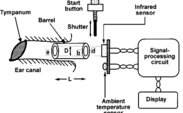
The internal structure of a human ear and a tym-panic thermometer are represented schematically in Fig. 1. The thermometer consists mainly of five parts, an IR sensor, a barrel, a shutter, an ambient-temperature sensor, and the associated circuit. The ear canal guides sound to the eardrum, which is thin and flooded with blood at the core temperature. The barrel, usually a cylindrical pipe with a highly reflec-tive inner surface for confining the radiation, is adap-tive to the outer canal without contacting the eardrum. The shutter controls whether the flux is
transferred to the IR sensor. When the shutter is open, radiative fluxes transfer among the tympanum, the IR sensor, and the inner surface of the barrel. The ambient sensor is mounted near the IR sensor to monitor the ambient temperature.
To measure core temperature, a tympanic ther-mometer is inserted into a patient’s outer ear canal. A start button is pressed to open the shutter momen-tarily and to start the measurement through the ra-diation exchanges. The electrical signal read out from the detector is fed to the circuit for amplification and calculation. The measured temperature then appears on a display. The total operation takes a few seconds.
The tympanic temperature can be determined by the net radiative flux falling on the IR sensor Qd, and
the ambient or detector temperature Td. In steady state, the tympanic temperature Tecan be calculated
according to the blackbody radiation law and conser-vation of energy and reads12
Te5
S
cQd εdεe 1 Td4D
1y4 5S
cVs εdεeRv 1 Td4D
1y4 , (1)with Qd5 VsyRv. HereRvis the detector voltage responsivity, Vsis the detector output voltage,εis the
emissivity, and T is the absolute temperature. Sub-scripts e and d denote the eardrum and the detector, respectively, and c is a constant related to device geometry and parameters. Hence, to measure the eardrum temperature Te, one must know the instan-taneous detector temperature Td and calibrate the
product of constants cy~εeεdRv!.
The product of constants can vary with time and measurement conditions. Chronic variation of the detector responsivity Rv is the most troublesome.
Rv is generally influenced by ambient temperature
and detector aging. Therefore the device requires constant calibration during use. Also, to avoid mea-surement errors resulting from the effects of the tem-perature drift of the barrel and the sensor substrate ~the ambient-temperature effect!, the outer part of the barrel is surrounded with plastic material serving as the thermal blanket and the inner surface is opti-cally polished to reduce its emissivity. However, since the ambient-temperature effect is still large compared with the weak radiation signal on the de-tector, its influence demands more careful analytical study.
B. Radiant Heat Exchanges
When one is designing a noncontact tympanic ther-mometer, it is most important to estimate the content of the net radiant flux on the IR sensor, Qd. The
detector receiving flux both from the tympanum and from the inner surface of the barrel complicates this estimate. This surface not only emits radiation by itself but also reflects that from the outside. A model that describes the radiant exchanges among all surfaces has been developed to clarify the role of the barrel on tympanic temperature measurements. To begin, for the simple case of radiant exchange
from an opaque diffusive surface i of area Ai and
emissivityεi, the net increased flux on the surface Qi
can be expressed as Qi5 εi 12εi Ai~Ji2 Ei! 5 1 ri ~Ji2 Ei!, (2)
where ri215 Aiεiy~1 2εi! is defined as the surface
resistance.13 Here J
iis the total exitance; Eiis the
blackbody emittance, which is sTi
4
; and s is the Stefan–Boltzmann constant. For the case of radia-tion exchange between two separate surfaces, Aiand
Aj, the flux quantity transferred from i to j, Qijcan be
written as14 Qij5 JiAiFij, (3) with Fij5 1 Ai
*
A i*
Aj cosuicosuj pRij2 dAidAj. (4)Here Rijis the distance between the two surfaces,ui
andujare the projected angles between Rij and the two surface normals, and Fijis called the view factor
that obeys the reciprocity,
AiFij5 AjFji. (5)
Extending the exchange theory to an enclosure com-prising N1 1 surfaces, i and j ranging from 1 to N, the net increased flux on the surface i can be derived, with the aid of the identity
(
j51N Fij; 1 (6) as Qi5(
j51 N AjFjiJj2 AiJi 5(
j51 N AiFij~Jj2 Ji! 5(
j51 N 1 rij ~Jj2 Ji!, (7)where rij215 AiFijis the space resistance.13 C. Radiation-Network Modeling
A radiation network can be set up to represent Eqs. ~2! and ~7!. Eiand Jiare equivalent to an
indepen-dent voltage source and a node potential, respective-ly; Qiis equivalent to a branch current from Jito Ei;
and the surface and space resistances, riand rij, are
analogs of the electrical resistances. This analogy allows direct application of the popular PSPICE cir-cuit simulation tool to simulate radiation-transfer problems.
As shown in Fig. 1, when the shutter is open the front and backsides and the inner surface of the cy-lindrical barrel form an enclosure. The front sur-face, e, is considered to be an effective surface standing for the tympanum with assumed unit emis-sivity. This assumption is justified by the fact that human tissue has a high emissivity of;0.99 ~Ref. 15! and that the inner tympanic cavity forms a black-body12that prevents reflection of radiation emitted
from the front barrel. The backside surface, d, where the IR sensor is installed is assumed to be the absorption layer of the IR sensor. Therefore the three surfaces, e, d, and b, constitute a closed radiant network that can be treated with Eqs. ~2! and ~7!. The correspondent equivalent-circuit model is shown in Fig. 2~a!.
Suppose the cylindrical barrel has a length L and a diameter D. Then the view factor between the de-tector and the eardrum, Fde, can be written as14
Fde5 1 1 2L2 D2 2 2 D@L~D 1 L!# 1y2. (8)
The other two view factors, Fdband Feb, equal each
other because of the symmetric geometry, and by Eq. ~6!,
Fdb5 Feb5 1 2 Fde. (9)
Substituting Eqs.~8! and ~9! into Eq. ~7!, we can write the space resistances rde, rdb, and rebof the tympanic
enclosure in more detail.
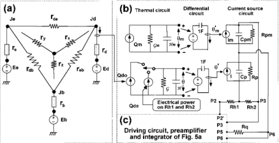
We can solve the net flux absorbed by the IR sensor,
Fig. 2. Opto-electro-thermal PSPICE model of the present tympanic thermometer: ~a! ra-diant network model,~b! electrothermal model of the pyroelectric sensor model, and~c! asso-ciated circuit.
Qd, by using D 2 Y transformations. The results give the three branches of a Y network:
rx5 rdereb rde1 reb1 rdb , (10a) ry5 rderdb rde1 reb1 rdb , (10b) rz5 rdbreb rde1 reb1 rdb , (10c)
as shown in Fig. 2~a!. Hence
Qd5 GeEe1 GbEb1 GdEd 5 GesTe 41 G bsTb 41 G dsTd 4 (11) with Ge5 rz1 rb ~rd1 rx!~rz1 rb! 1 ~ry1 re!~rz1 rb1 rd1 rx! , (12a) Gb5 ry1 re ~rd1 rx!~ry1 re! 1 ~rz1 rb!~ry1 re1 rd1 rx! , (12b) Ge5 2 rz1 rb1 ry1 re ~rz1 rb!~ry1 re! 1 ~rd1 rx!~rz1 rb1 ry1 re! . (12c) Note that Ge1 Gb1 Gd5 0, which is a natural result
of the conservation of energy, and can be proved sim-ply by setting all the surfaces to be isothermal.
The core temperature Te therefore can be deter-mined from Eq.~11! as
Te5
S
Qd sGe 2Gd Ge Td 4 2Gb Ge Tb 4D
1y4 . (13)This equation is more complete than the simple the-ory of Eq. ~1!, because the barrel temperature has been included. The relative roles of Td and Tb in
determining the net radiation Qdtherefore are more accurately expressed.
D. Temperature Effect of the Barrel
If we assume that Tb5 Td5 Ta, owing to the close-ness of the barrel and the sensor, Tecan be simplified
to Te5
S
Qd sGe 1 Ta4D
1y4 5S
1 sGe Vs Rv 1 Ta4D
1y4 . (14) Equation ~14! expresses explicitly the calibration factor c in Eq. ~1!. In reality, this assumption is seldom correct unless the temperatures of the barrel and the ear canal are identical. Contact between the two solids causes heat transfer across the barrel due to their temperature difference. The average temperature of the barrel thus is time-varying during measurements, and Eq. ~14!, which is based on theassumption of identical temperatures, may not be accurate enough. Unfortunately, the temperature drift of the barrel during the measurement is difficult to predict; hence it is important to design a barrel that can make the drift effect small enough to be acceptable or even ignored.
Suppose that initially Tb5 Td5 Taand the tem-perature of the barrel changes a small amount,dTb,
after ear contact; then by differentiation of Eq.~13!, dTe5 2 Gb Ge z Tb 3z
S
Qd sGe 2Gd Ge Td 42Gb Ge Tb 4D
23y4U
Ta z ~dTb! (15) In medical thermometry,dTeis generally expected tobe within 0.1 °C. In addition, human temperature is normally meaningful between 30 and 43 °C.1
Tem-peratures outside this range are vitally dangerous. Furthermore the working ambient-temperature range of a commercial tympanic thermometer is gen-erally defined from 24 to 45 °C. The worst case of Eq.~15! is that Te5 30 °C ~303 K! and Ta 5 45 °C
~318 K!. Accordingly, the drift of the barrel is lim-ited to a maximal value,
udTbmu 5 udTeu z
S
Te TaD
3 zU
Ge GbU
5 0.095 3U
Ge GbU
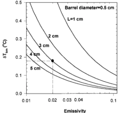
. (16) The maximal allowable drift of the barrel tempera-ture is ;10% of the ratio of Ge to Gb. These two quantities, which appeared in Eqs.~12a! and ~12b!, are a complicated function of the various parameters of a tympanic network. Therefore it is more conve-nient to apply the PSPICE simulation tools directly to the model shown in Fig. 2. The results of the sim-ulation in various conditions are shown in Fig. 3. On the one hand, when the barrel length is fixed, the maximal allowable drift decreases rapidly with in-creasing emissivity of the inner surface of the barrel. This is obvious since the radiance from the barrel will increase. On the other hand, the allowable driftin-Fig. 3. Plot of the maximal allowable temperature driftdTbmof
the barrel with different inner surface emissivities and lengths. When these are 0.02 and 3 cm, respectively,dTbmis 0.18 °C as
creases with a shorter barrel, because the IR sensor perceives a larger field of view. Thus one can con-clude that a shorter barrel length and a higher re-flectance on the inner surface of the barrel are desirable. However, the length is limited by the ca-nal geometry, whereas the reflectance depends on coating quality. For a reasonable length of 3 cm and a reflectance of 0.98 by the gold coating,15 dT
b is
tolerable to as high as 0.18 °C, as indicated in Fig. 3. According to our theoretical prediction, a plastic case surrounding the barrel can successfully restrict the average temperature variation of the barrel below 0.05 °C for a 10-s measurement period.
3. Electrically Calibrated Design
To analyze the detecting mechanics of the pyroelec-tric sensor, we require a heat-flow and a charge-flow equation16,17: *du~t! dt 1 &u~t! 5 Qd~t!, (17) CL dV~t! dt 1 1 RL V~t! 5 pAd du~t! dt . (18)
Here* and & denote the thermal capacitance and the conductance of the sensor, CLand RLare the output
capacitance and the resistance, p is the pyroelectric coefficient, Ad is the detector area, and V~t! is the
output voltage. The detector receiving power Qd
de-fined in Eq. ~11! generates the excess temperature u~t!. The net irradiance on the detector is expressed by
Qd~t! 5 Qdo@u~t! 2 u~t 2 to!#, (19)
where u~t! is the unit step function, Qdo, is the
am-plitude, and tois the one-shot period. Substituting
Eqs. ~17! and ~19! into Eq. ~18!, we read the final signal for integration-mode operation as
So5
*
0 to V~t!dt 5H
pAd CL*S
tett te2 ttDF
2teexpS
2 to teD
1 ttexpS
2 to ttD
1 te2 ttGJ
z Qdo 5 Rvz Qdo, (20) where te5 RLCL, tt5 *y&, (21)are the detector electrical and thermal time con-stants, respectively. The voltage responsivityRvis
defined in the parentheses of Eq.~20!.
By substituting Eq.~20! into Eq. ~14!, we can obtain the core temperature explicitly. The measured value therefore depends on the detector responsivity, which is influenced by the electrical and the thermal parameters contained in Eq. ~20!. However, these
parameters vary with manufacturing processes; henceRvvaries from detector to detector.
Further-more material aging also produces long-term changes in each detector, especially aging of the pyroelectric coefficient. Therefore initial factory calibration will not suffice for long-term use. As proposed in many articles,4,5,12it becomes necessary to calibrate the
in-strument before every measurement. This often leads to complex circuitry in practical situations.
To solve this problem, we propose an electrically calibrated method that is both accurate and simple in circuit design. With the present method, an artifi-cial electric pulse is applied to a thin-film heater coated on the sensor surface following exposure to the eardrum radiation. The response of the electric pulse is integrated for a duration identical to the optical exposure to in Eq.~19!. This gives an elec-trical signal of Sesimilar to Eq.~20!, and the
radia-tion energy can be calibrated proportionally. Equation~14! then can be expressed by
Te5
S
Qde sGe So Se 1 Ta 4D
1y4 . (22)Note that this Qdeis the electrical power applied on the heater for a calibration reference and can be mea-sured precisely. The measured core temperature Te thus is independent of the responsivity variations discussed previously.
One could also use Eqs.~17! and ~18! to establish a PSPICE equivalent circuit to represent the electro-thermal behavior of the pyroelectric sensors.18,19
This is shown in Fig. 2~b!, where lump representations are used for both the thermal parameters, * and &, and the electrical parameters, Cp and Rp. The sub-script m represents the dummy parts as shown in Fig. 2~b!. The induced pyroelectric current is represented by a current source I controlled by the temperature difference u9 from the output of the thermal circuit through a differentiator. Two current-controlled cur-rent sources represent the heat power from radiation ~Qdo! and the electrical heating power ~Qde!.
With such representations, both the radiation ex-change and the thermal properties of the sensor can be incorporated with regular electrical circuits into an integrated circuit model as shown completely in Fig. 2. This allows tools such as PSPICE to be used directly for system simulation. The opto-electro-thermal PSPICE model is invaluable to a system en-gineer in obtaining optimal design for a tympanic thermometer.
4. Experiments and Results
A. Electrically Calibrated Pyroelectric Detector
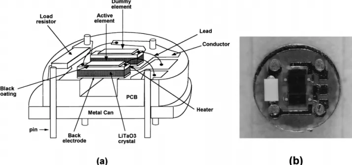
The electrically calibrated pyroelectric detector for the experiment is shown in Fig. 4. The sensor con-tains two pyroelectric elements made of LiTaO3, an
active one and a dummy, with both floating. A high impedance resistance is used as the output load. All these are mounted on a printed circuit board~PCB! and packed into a TO-metal can structure. This
de-tector structure is very similar to that used in the current commercial pyroelectric tympanic thermom-eter,5except the active element is coated with a
thin-film heater ~;600 V! on its upper surface. The dummy element is shielded from illumination by an opaque mask over it. To reduce the microphonic ef-fect, the polarizations of the active and dummy sen-sors are arranged in opposite directions to cancel the piezoelectrically induced charges.
B. Circuits
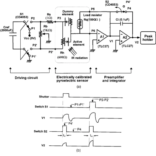
The circuit for electrical calibration is depicted in Fig. 5~a!. An energy-storage capacitor of 2000 uF, Cref, is used for reference heating. The capacitor is pre-charged by Vcc through switch S1 ~CD4053! at the P1–P19 positions. After switching to the P2–P29 po-sitions, the capacitor starts to heat the active element through the heating resistor Rh. As shown in Fig. 5, isolation of the capacitor during heating ensures that the detector output signal is free from any false signal that might be fed through the detector capacitance if the detector were directly heated by Vcc. The capacitor-isolated-heating configuration therefore improves the power supply rejection ratio~PSRR! of the measurement significantly. A 1-V resistor Rs in series with the heater Rh is used to read the heating current for the electrical power calculation. A vari-able resistance Rb between P2 and P29 is used to ensure that the sensor output voltage is referred to the preamplifier ~A1! ground through a balanced bridge configuration, because the ground potential of the active sensor on heater electrode Rh is floating and is not accessible.19 –21
The induced weak pyroelectric current is converted to a voltage through preamplifier A1. A large load resistor Rqmounted inside the package is used as the
feedback resistor to the preamplifier to increase the gain. An AD590M IC is used to sense accurately the
ambient temperature by the proportional-to-absolute-temperature method.22 This is of
para-mount importance for the accuracy of the
thermometer as indicated in Eq. ~22!. Figure 5~b! shows the timing sequence of the operation.
C. PSPICE Simulation
Using the opto-electro-thermal model established above, we are able to simulate the behavior of any pyroelectric tympanic thermometer. Two cases are studied, the con-ventional non-ECP method and the present ECP method. The device parameters were extracted by the bolometric method previously used in our laboratory,18,19
which gives the following data: p5 6 3 1029Cycm2,& 5 0.0008 Wy°C, * 5 0.003 Jy°C, and Rv5 1252 VyW.
We calibrate theRvvalue of the tested sample by
refer-ring to a blackbody at 37 °C.
Figure 6 shows the results of the simulation. We vary the pyroelectric constant and thermal conduc-tance by 50% to allow for practical deviations in man-ufacturing. For a thermometer using a conventional non-ECP sensor, the measured temperature could de-viate over several tens of degrees away from the as-sumed true temperature of 37 °C. This is much larger than the medical allowance of 0.1 °C described above. Curve~a! in Fig. 6 indicates that if the py-roelectric constant were changed by only 1%, the measured temperature would be in error by 0.216 °C. Similarly, the error is 0.181 °C for a change of 1% in the conductance as seen in curve ~b!. The simula-tion thus proves that the measured temperature is very sensitive to variations in the device parameter, which cannot be avoided in real situations. There-fore precise in-factory calibration and a good circuit design are necessary to compensate for the parame-ter variations of the individual detectors and the ag-ing of the detector material in chronic use of a tympanic thermometer.
Curve ~c! of Fig. 6 also shows the results of the simulation of the present ECP thermometer, where differences in the device parameters of the two pyro-electric elements are allowed. It is evident that the
ECP method is independent of device variation as predicted by the theory.
D. Experimental Measurements
Using the fabricated ECP sensors in Fig. 4 and the circuits shown in Fig. 5, we are able to test the
Fig. 5. ~a! Readout and calibra-tion circuits including driving cir-cuit, ECP, and dummy sensors, preamplifier, integrator, and peak holder. ~b! Timing diagram.
Fig. 6. Simulation results of the model in Fig. 2 showing the relation of the measured temperature to the thermal conductance and pyroelectric constant. A measured temperature of 37 °C is set to represent a human’s eardrum when the device parameters are p5 6 3 1029Cycm2,& 5 0.0008 Wy°C, * 5 0.003 Jy°C, and
Rv5 1252 VyW.
Fig. 7. Measurement errors as a function of ambient tempera-ture. Cross points are from our thermometer without the ECP method being utilized. Circles are from the present ECP method, and solid squares are the data taken by Cascetta8from a
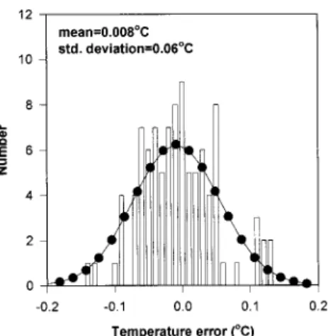
ambient-temperature effect of our ECP tympanic thermometer. The tympanic thermometer is set up in front of a reference blackbody, which simulates the human eardrum at 37 °C. The measured values were recorded while the ambient temperature changed from 17 to 37 °C. The results are shown in Fig. 7. The vertical axis represents the measured temperature relative to 37 °C. The square points represent the data from the commercial tympanic thermometer described by Cascetta.8 The cross
points are from the device described here without use of the ECP method, while the circles are for the same device with the ECP method. Note that the electri-cally calibrated tympanic thermometry is superior to the other two methods and is able to meet the clinical criterion of 0.1 °C accuracy across a wider ambient temperature range. Also shown in Fig. 8 is the error distribution for 100 measurements in various situa-tions, including different ambient and core tempera-tures. A normal distribution is used to fit these data, which gives a calculated mean and a standard deviation of 0.008 and 0.06 °C, respectively. This means that the present ECP thermometer has an accuracy of 0.1 °C with 90% confidence. These sults show that the ECP method is effective and re-liable when applied to tympanic thermometry.
5. Conclusion
A new tympanic thermometer utilizing a modified ECPR technique has been analyzed theoretically and demonstrated experimentally. This method is not influenced by ambient temperature and detector ag-ing and is able to provide the accuracy required by clinical applications. The theoretical analysis pro-vides a base for establishing an integrated opto-electro-thermal PSPICE model capable of simulating the tympanic thermometer. This model can be mod-ified to accommodate other thermal detectors18 and
applied to other applications relating to radiation thermometry.
The authors are obliged to Opto Tech Corporation and Oriental System Technology Inc. in Hsinchu Science-Based Industrial Park for invaluable techni-cal support in the fabrication of the pyroelectric sen-sor package and the experimental setup, respectively.
References
1. J. G. Webster, Encyclopedia of Medical Devices and
Instrumen-tation, Vol. 4~Wiley, New York, 1988!, pp. 2723–2730.
2. T. H. Benzinger, “On physical regulation and the sense of temperature in man,” Proc. Natl. Acad. Sci. 45, 645– 649 ~1959!.
3. M. Benzinger, “Tympanic thermometry in anesthesia and sur-gery,” J. Am. Med. Assoc. 209, 1207–1211~1969!.
4. G. J. O’Hara and D. B. Phillips, “Method and apparatus for measuring internal body temperature utilizing infrared emis-sions,” U.S. patent 4,602,642~29 July 1986!.
5. J. Fraden, “Infrared electronic thermometer and method for measuring temperature,” U.S. patent 4,797,840~10 January 1989!.
6. J. Jakobsson, A. Nilsson, and L. Carlsson, “Core temperature measured in the auricular canal: comparison between four different tympanic thermometers,” Acta Anaesthesiol. Scand. 36, 819 – 824~1992!.
7. M. E. Weiss, A. F. Pue, and J. Smith III, “Laboratory and hospital testing of new infrared tympanic thermometer,” J. Clin. Eng. 16, 137–144~1991!.
8. F. Cascetta, “An evaluation of the performance of an infrared tympanic thermometer,” Measurement 16, 239 –246~1995!. 9. J. Geist and W. R. Blevin, “Chopper-stabilized null radiometer
based upon and electrically calibrated pyroelectric detector,” Appl. Opt. 12, 2532–2535~1973!.
10. W. M. Doyle, B. C. Mcintosh, and J. Geist, “Implementation of a system optical calibration based on pyroelectric radiometry,” Opt. Eng. 15, 541–548~1976!.
11. F. Hengstberger, Absolute Radiometry: Electrically Cali-brated Thermal Detectors of Optical Radiation ~Academic,
New York, 1989!, pp. 1–116.
12. J. Fraden, “Noncontact temperature measurements in medi-cine,” in Bioinstrumentation and Biosensors~Marcel Dekker, New York, 1991!, pp. 511–549.
13. A. K. Oppenhein, “Radiative analysis by network method,” Trans. Am. Soc. Mech. Eng. 78, 725–735~1956!.
14. J. P. Holman, Heat Transfer, 7th ed.~McGraw-Hill, New York, 1992!, pp. 385–506.
15. R. D. Hudson, Infrared System Engineering~Wiley, New York, 1969!, pp. 20–113.
16. J. Copper, “Minimum detectable power of a pyroelectric ther-mal receiver,” Rev. Sci. Instrum. 33, 92–95~1962!.
17. M. Simbony and A. Shaulov, “Pyroelectric voltage response to step signals of infrared radiation in triglycine sulphate and strontium-barium niobate,” J. Appl. Phys. 42, 3741–3744 ~1971!.
18. J. S. Shie, Y. M. Chen, M. Ou-Yang, and B. C. S. Chou, “Char-acterization and modeling of metal-film microbolometer,” IEEE J. Microelectromech. Syst. 5, 298 –306~1996!.
19. M. Ou-Yang, “Implementation of absolute optical power meter with single-chip controller,” M.S. thesis~National Chiao Tung University, Taiwan, 1993!.
20. J. S. Shie, J. C. Hong, and G. H. Yu, “Design of electrically calibrated pyroelectric radiometer,” J. Chin. Inst. Eng. 12, 239 –247~1989!.
21. R. J. Phelan and A. R. Cook, “Electrically calibrated pyroelec-tric optical–radiation detector,” Appl. Opt. 12, 2494 –2500 ~1973!.
22. M. P. Timko, “A two-terminal IC temperature transducer,” IEEE J. Solid-State Circuits SC-11, 784 –788~1976!.
Fig. 8. Error distribution of 100 experiments in various condi-tions. The mean error is 0.008 °C, and the standard deviation is 0.06 °C. These results imply that each measurement has a 90% confidence for an accuracy within 0.1 °C.