Open Access
Research
An ultra-low-power image compressor for capsule endoscope
Meng-Chun Lin*
1, Lan-Rong Dung
1and Ping-Kuo Weng
2Address: 1Department of Electrical and Control Engineering National Chiao Tung University, Hsinchu, Taiwan and 2Solid-State Devices Section, Materials and Electro-Optics Research Division, Chung-Shan Institute of Science and Technology, Lung-Tan, Tao-Yuan, Taiwan
Email: Meng-Chun Lin* - [email protected]; Lan-Rong Dung - [email protected]; Ping-Kuo Weng - [email protected]
* Corresponding author
Abstract
Background: Gastrointestinal (GI) endoscopy has been popularly applied for the diagnosis of
diseases of the alimentary canal including Crohn's Disease, Celiac disease and other malabsorption disorders, benign and malignant tumors of the small intestine, vascular disorders and medication related small bowel injury. The wireless capsule endoscope has been successfully utilized to diagnose diseases of the small intestine and alleviate the discomfort and pain of patients. However, the resolution of demosaicked image is still low, and some interesting spots may be unintentionally omitted. Especially, the images will be severely distorted when physicians zoom images in for detailed diagnosis. Increasing resolution may cause significant power consumption in RF transmitter; hence, image compression is necessary for saving the power dissipation of RF transmitter. To overcome this drawback, we have been developing a new capsule endoscope, called GICam.
Methods: We developed an ultra-low-power image compression processor for capsule
endoscope or swallowable imaging capsules. In applications of capsule endoscopy, it is imperative to consider battery life/performance trade-offs. Applying state-of-the-art video compression techniques may significantly reduce the image bit rate by their high compression ratio, but they all require intensive computation and consume much battery power. There are many fast compression algorithms for reducing computation load; however, they may result in distortion of the original image, which is not good for use in the medical care. Thus, this paper will first simplify traditional video compression algorithms and propose a scalable compression architecture.
Conclusion: As the result, the developed video compressor only costs 31 K gates at 2 frames per
second, consumes 14.92 mW, and reduces the video size by 75% at least.
Background
Gastrointestinal (GI) endoscopy has been popularly applied for the diagnosis of diseases of the alimentary canal including Crohn's Disease, Celiac disease and other malabsorption disorders, benign and malignant tumors of the small intestine, vascular disorders and medication
related small bowel injury. There exist two classes of GI endoscopy; wired active endoscopy and wireless passive capsule endoscopy. The wired active endoscopy can ena-ble efficient diagnosis based on real images and biopsy samples; however, it causes patients discomfort and pain to push flexible, relatively bulky cables into the digestive
Published: 25 February 2006
BioMedical Engineering OnLine 2006, 5:14 doi:10.1186/1475-925X-5-14
Received: 02 November 2005 Accepted: 25 February 2006 This article is available from: http://www.biomedical-engineering-online.com/content/5/1/14
© 2006 Lin et al; licensee BioMed Central Ltd.
This is an Open Access article distributed under the terms of the Creative Commons Attribution License (http://creativecommons.org/licenses/by/2.0), which permits unrestricted use, distribution, and reproduction in any medium, provided the original work is properly cited.
tube. To relief the suffering of patients, wireless passive capsule endoscopes are being developed worldwide [1-4]. The capsule moves passively through the internal GI tract with the aid of peristalsis and transmits images of the intestine wirelessly.
The state-of-the-art is the commercial wireless capsule endoscope product, the PillCam capsule, developed by Given Imaging Ltd. The PillCam capsule transmits the GI images at the resolution of 256-by-256 8-bit pixels and the frame rate of 2 frames/sec (or fps). The PillCam has been successfully utilized to diagnose diseases of the small intestine and alleviate the discomfort and pain of patients. However, based on clinical experience; the PillCam still has some drawbacks. First, the PillCam cannot control its heading and moving direction itself. This drawback may cause image oversights and miss a disease. Second, the res-olution of demosaicked image is still low, and some inter-esting spots may be unintentionally omitted. Especially, the images will be severely distorted when physicians zoom images in for detailed diagnosis. The first drawback is the nature of passive endoscopy. Some papers have pre-sented approaches for the autonomous moving function [5,6]. Very few papers address the solutions of the second drawback. Increasing resolution may alleviate the second problem; however, it would result in significant power consumption in RF transmitter. Hence, applying image compression is necessary for saving the power dissipation of RF transmitter. The paper [11] provides a thorough review on GI image compression and motivated our research. To overcome the second drawback, we have been developing a new capsule endoscope, called GICam. Fig. 1 illustrates the system diagram of the proposed cap-sule endoscope. We attached an ultra-low-power image compressor to the CMOS sensor to deliver a compressed 512-by-512 image while the RF transmission rate is at 2 megabits per second. To reduce the buffer size between the CMOS sensor and the image compressor, the scanline
controller is dedicated to scan out R, G1, G2, and B signals in a certain order.
The scope of this paper is the design of an image compres-sion processor for capsule endoscopes. Instead of apply-ing existapply-ing compression standards, we developed simplified image compression specifically for capsule endoscopes. Unlike the general image compression tech-niques, the proposed image compression starts from raw images in the format of Bayer patterns and processes R,
The Bayer patterns in the raw image Figure 3
The Bayer patterns in the raw image.
G2 R G2 R G1 B G1 B R G2 R G2 G1 B G1 B R G2 R G2 G1 B G1 B R G2 R G2 ΘΘΘ ΘΘΘ ΘΘΘ ΘΘΘ G2 R R G1 B G1 R G2 R G1 B G1 R G2 R G1 B G1 R G2 R ΘΘΘ ΘΘΘ ΘΘΘ G2 B G2 B G2 B G2 ΘΘΘ ΘΘΘ ΘΘΘ ΘΘΘ ΘΘΘ ΘΘΘΘ Θ
512
512
A unit of Bayer pattern The system structure of GICam (1: Len; 2,3: LEDs; 4: CMOSsensor; 5: Image compressor; 6: Scanline controller; 7: Bat-tery; 8: RF transmitter; 9: Antenna)
Figure 1
The system structure of GICam (1: Len; 2,3: LEDs; 4: CMOS sensor; 5: Image compressor; 6: Scanline controller; 7: Bat-tery; 8: RF transmitter; 9: Antenna).
3
2
1
4
5
6
7
8
9
(a) A typical image compression algorithm (b) The GICam image compression algorithm
Figure 2
(a) A typical image compression algorithm (b) The GICam image compression algorithm.
Demosaicking 2-D DCT Color Space Transform 2-D DCT 2-D DCT Quantization Y-table Quantization Cb-table Quantization Cr-table Entropy Coding Raw Image Compressed Y image Compressed Cbimage Compressed Crimage (a) 2-D DCT 2-D DCT 2-D DCT 2-D DCT Quantization G-table Quantization R-table Quantization G-table Quantization B-table Compression Image for G1 Compression Image for R Compression Image for G2 Compression Image for B Raw Image Entropy Coding Entropy Coding Entropy Coding Entropy Coding Entropy Coding Entropy Coding (b)
G1, G2, and B signals separately. Comparing with the tra-ditional image compression, the proposed image com-pression is low-powered for three reasons. First, the proposed image compression does not need demosaick-ing, and hence saves the computing power of interpola-tion steps. Second, the proposed compression starts from the raw image, and does not need inner product opera-tions for color-space transformation. Finally, the compu-tation load of the 8-by-8 discrete cosine transform (DCT) can be reduced by the factor of 3.
Methods
The proposed image compression algorithm
Traditional image compression algorithms use the opti-mized quantization for YCbCr image to reduce com-pressed image size while the visual distortion is low. In order to quantize YCbCr image, the typical image com-pression requires two preprocessing steps that are demo-saicking and the color space transformation. However, the demosaicking step requires weighted sums for color inter-polation and the color space transformation requires cal-culation of inner products. From the view point of GICam, it is not worth it to dissipate power for both pre-processing steps as long as the compression quality and ratio are acceptable. The measure of compression quality is the peak signal-to-noise ratio (PSNR). The calculation of PSNR is formulated as Eq. (1):
Where MSE is the mean square error of decompressed image. The compression ratio (CR) is defined as the ratio of the raw image size to the compressed image size. The measure of the compression ratio is the compression rate. The formula of the compression rate is calculated by Eq. (2):
compression rate = (1-CR-1) × 100% (2)
Fig. 2 illustrates the power saving on the proposed image compression. First of all, the GICam image compression directly processes raw images without demosaicking and color space transform. For a 512 × 512 image, when using the Bayer format, the image has 256 × 256 Bayer patterns. Fig. 3 shows the Bayer patterns in the CMOS image sensor. So, the incoming image size to the 2D-DCT is 256 × 256 × 8 × 4 bits, where each pixel is an 8-bit datum and each of R, G1, G2, and B components has 256 × 256 pixels. Since the image size after preprocessing in the traditional algorithm is 512 × 512 × 8 × 3 bits, the computational load of 2D-DCT and quantization is reduced by the factor of 3. Traditional compression algorithms employ the YCbCr quantization to earn a good compression ratio while the visual distortion is minimized, based on the fac-tors related to the sensitivity of the human visual system (HVS). However, for the sake of power saving, our
com-PSNR MSE =
( )
10 255 1 2 log ,The modified RGB quantization table Figure 4
The modified RGB quantization table.
ˊˇ
ˊˈ
ˊˉ
ˊˊ
ˊˋ
ˊˌ
ˋ˃
ˋ˄
ˋ˅
ˋˆ
ˋˇ
ˋˈ
ˋˉ
ˋˊ
ˋˋ
˄
˅
ˆ
ˇ
ˈ
ˉ
ˊ
ˋ
ˌ
˄˃
˄˄
˄˅
˧˸̆̇ʳˣ˼˶̇̈̅˸ʳ˜˗
˖
̂̀
̃̅˸
̆̆
˼̂
́ʳ
̅˴
̇˸
ʻʸ
ʼ
w=32, l=16
w=32, l=32
w=32, l=64
w=64, l=16
w=64, l=32
w=64, l=64
w=128, l=16
w=128, l=32
w=128, l=64
pression rather uses the RGB quantization to save the computation of demosaicking and color space transfor-mation. According to [7], the RGB quantization can result in similar decompressed image quality as the YCbCr
quan-tization. As mentioned above, the advantage of applying RGB quantization is two-fold: saving the power dissipa-tion on preprocessing steps and reducing the computing load of 2D-DCT and quantization. Although the RGB quantization for the Bayer-formatted image requires four quantizing products, the number of tables is three in that G1 and G2 components can share the same green quanti-zation table. Moreover, to reduce the hardware cost and quantization power dissipation, we modified the RGB quantization tables in [7] as shown in Fig. 4. In the mod-ified tables, the quantization multipliers are power-of-two's. As shown in the simulation result, the degradation of compressed image is low when comparing with the original RGB quantization. The minor shortcoming of the RGB quantization is that the quantization latency is longer than the YCbCr quantization when the R-G1-G2-B
quantizations are pipelined. Thanks to the low frame rate specification in capsule endoscopy, the increasing of quantization latency is acceptable.
In GICam, the Lempel-Ziv (LZ) coding [8] is employed for the entropy coding. The reason why we adopted the LZ coding as the entropy coding is that the LZ encoding does not need look-up tables and complex computation. Thus, the LZ encoding can consume less power and use smaller silicon size than the other candidates, such as the Huff-man encoding and the arithmetic coding.
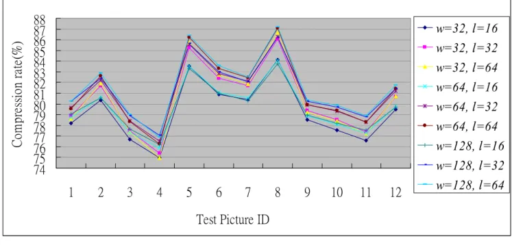
The target compression performance of the GICam image compression is to reduce image size by 75% at least. To meet the specification, given the quantization tables, we exploited the cost-optimal LZ coding parameters. There are two parameters in the LZ coding to be determined; they are the window size, w, and the maximum matching length, l. The larger the parameters, the higher the com-pression ratio but the higher the implementation cost. As
The simulation results of the GICam image compression Figure 5
The simulation results of the GICam image compression.
256 256 256 128 128 128 64 64 256 128 128 128 128 64 64 64 128 128 128 64 64 64 32 32 128 128 64 64 32 32 32 16 128 64 64 32 16 16 16 16 128 64 32 32 16 16 16 16 64 64 32 32 16 16 16 16 64 32 32 16 16 16 16 16
R quantization table
1024 1024 1024 512 512 512 256 256 1024 512 512 512 256 256 256 128 512 512 512 256 256 128 128 128 512 512 256 256 128 64 128 64 512 256 256 128 64 64 64 32 512 256 128 64 32 32 32 32 256 128 128 64 64 32 32 32 128 128 64 64 32 32 32 32B quantization table
128 128 128 128 128 64 64 64 128 128 64 64 64 32 32 32 64 64 64 64 32 32 16 32 64 64 64 32 32 32 16 16 64 64 32 32 32 16 8 16 64 32 32 16 16 8 8 16 32 32 16 16 16 8 16 16 32 32 32 16 16 16 16 16G quantization table
per the experimental results shown in the Fig. 5, the increase in compression ratio becomes very slow, as the parameters are large; however, the implementation cost keeps growing linearly. Hence, we set the values of param-eters by using the compression ratio of 4:1 as the thresh-old. Our goal is to determine the minimum (w, l) set under the constraint of 4:1 compression ratio. The results in Fig. 5 are collected by simulating the candidate LZ encoding schemes with the 8-by-8 2D-DCT and the RGB quantization. As seen in Fig. 5, simulating with 12 endo-scopic pictures, (64, 16) is the minimum (w, l) set to meet the compression ratio requirement. Using (64, 16) as the parameter set, in Fig. 6, we can see the performance in terms of the quality degradation and compression ratio. The result shows that the degradation of decompressed images is quite low while the average PSNR is 32.51 dB.
The block diagram of 2D-DCT Figure 9
The block diagram of 2D-DCT.
Sign
extension
2 t
o
1
MUX
011-D DCT
with
Algebraic Integer
Encoding
Transpose
memory
R G1 G2 B
image
12
12
12
8
12
12
Frequency
domain image
(a) Demosaicked images from raw images #5 and #8Figure 7
(a) Demosaicked images from raw images #5 and #8. (b) Demosaicked images from decompressed images #5 and #8.
(a)
Test image #5 Test image #8
(b)
Decompressed image #5 Decompressed image #8 The simulation results of twelve tested pictures
Figure 6
The simulation results of twelve tested pictures. 79.65 32.51 Average 79.75 31.51 12 77.30 35.04 11 78.08 32.25 10 78.89 33.77 9 84.04 33.95 8 80.57 29.82 7 81.05 31.08 6 83.52 35.27 5 75.86 32.63 4 77.35 31.12 3 80.63 32.00 2 78.75 31.74 1 Compression rate (%) PSNR (dB) Test Picture ID
The architecture of GICam image processor Figure 8
The architecture of GICam image processor.
8ͪ8
Memory
Compressed
image
R G1 G2 B
image
8
ͪ8
Memory
8ͪ8
2D-DCT
8
ͪ8
Quantizer
8
ͪ8
Memory
LZ77
Encoder
The original image involved in the PSNR calculation is the Bayer pattern image. According to the objective criterion of medical doctors the PSNR higher than 30 dB is accept-able. To demonstrate the results, Fig. 7 illustrates the com-pression quality of two test pictures. The difference between the original image and the decompressed image is invisible.
Architecture design and implementation of GIcam image compressor
Fig. 8 shows the architecture of the GICam image com-pressor. The GICam image compressor processes the image in the order of R, G1, G2 and B. Because the data stream from the image sensor is block-based, the GICam
image compressor requires intermediate memory units to hold each block of data. Because the 2D-DCT is a row-col-umn recursive structure, its input data are queued by a set of ping-pong buffers. In addition, the 8-by-8-memory array between the quantizer and the LZ77 encoder is used to synchronize the operations of quantization and LZ77 encoding. Since the frame rate of GICam is 2 frames/sec-ond, the 2D-DCT can be folded to trade the hardware cost with the computing speed, and the other two data processing units, quantization and LZ77 encoder, can operate at low data rate.
The FPGA prototype of the CICam image compressor Figure 13
The FPGA prototype of the CICam image compressor.
The block diagram of LZ 77 encoder Figure 11
The block diagram of LZ 77 encoder. (LMDB: Longest match length decision block)
LMDB
MUX
B0
i
optL
maxcwr
L
i8
8
6
From 8x8 memory
Wrapper
Circuit
Encoded Bit
Stream
6
6
B1 … B63 M0
M1
… M15
PE0 PE1
…
PE15
8
8
8
8
8
The block diagram of Quantizer Figure 10
The block diagram of Quantizer.
G
quantization
table
R
quantization
table
B
quantization
table
3 to 1 MUX
10
01
00
Barrel shifter
4
4
4
Image from
2D-DCT
12
8
Quantized Image
Counter
CLK cen
4
6
sen
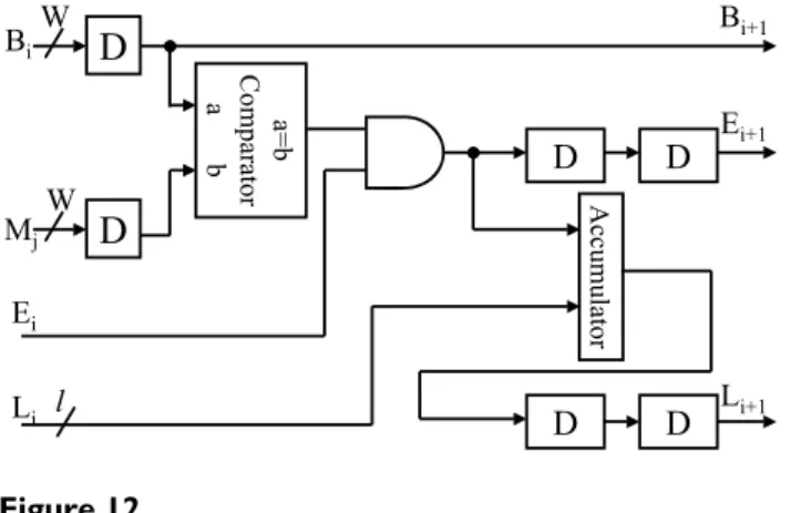
The circuit of PE in the LZ77 encoder Figure 12
The circuit of PE in the LZ77 encoder.
D
a=b Com par at or a b D D D DD
Acc umula tor W W Bi Mj Ei Li l Ei+1 Bi+1 Li+1Fig. 9 illustrates the block diagram of DCT. The 2D-DCT alternatively calculates row or column 1D-2D-DCTs. The 1D-DCT is a multiplier-less implementation using the algebraic integer encoding [10]. The algebraic integer encoding can minimize the number of addition opera-tions. Doing so, we can produce a low-cost, power saving DCT datapath. According to the report from Prime-Power™, the logic part of 2D-DCT consumes 1.53 [email protected] MHz and the transpose memory costs 2.80 mW. As regards the RGB quantizer, the GICam image processor utilizes the barrel shifter for power-of-two prod-ucts. The power-of-two quantization table shown in Fig. 4 can reduce the cost of multiplication while quality degra-dation is quite little. As shown in Fig. 10, we use the barrel shifter to perform the quantization. According to the PrimePower™ report, the quantization consumes 0.115 mW. Finally, the LZ77 encoder is implemented by block-matching approach as shown in Fig. 11[9]. The detail of each processing element (PE) is shown in Fig. 12. As the result of simulation, the power consumption of LZ77 is 3.87 mW.
To validate the GICam image processor, we used the FPGA board of Altera APEX2100 K to verify the function of the
GICAM image processor and the prototype is shown in Fig. 13. Test results are the same as simulation results of the algorithm level using MTALAB. After FPGA verifica-tion, we used the TSMC 0.18 µm 1P6M process to imple-ment the GICam image compressor. The logic part is synthesized by using Synopsys Design Analyzer™. The gate count of 2D-DCT, quantizer, and LZ77 encoder is 31 K gates. There are two clocks in the chip. One at 1.57 MHz is for 2D-DCT and Quantizer, and another at 12.58 MHz is for LZ77 encoder. When operating at 1.8 V, the power consumption of logic part is 5.52 mW, estimated by using PrimePower™. The memory blocks are generated by Arti-san memory compiler and consume 9.40 mW. Fig. 14 illustrates the layout of the GICam image compressor. When comparing the proposed image compression with the traditional one in Fig. 15, the power dissipation can save 98.2% because of the reduction of memory require-ment. Except comparing with the traditional one, we fur-ther analysis the power saving from system perspective. For a 512-by-512 GI images, if we do not use the proposed image compressor to compress the data of GI image, the total power dissipation is 33.5 mW, in which, the sensor consumes 8 mW, the RF transmitter consumes 24 mW and LEDS consumes 1.5 mW respectively. However, the GICam compresses the GI image and total dissipation power is 33.5 mW. The power dissipation of the RF trans-mitter can be reduced to 6 mW and the proposed image compressor consumes 14.92 mW. Hence, using the pro-posed image compressor can efficiently save the total power dissipation of 3.08 mW and substantially reduce
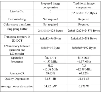
The comparison of proposed image compression and the tra-ditional image compression applying for GICam application Figure 15
The comparison of proposed image compression and the tra-ditional image compression applying for GICam application.
Proposed image compressionʳ Traditional image compression Line bufferʳ 0 3ͪ512ͪ8=1536 Bytes
Demosaicking Not required Required
Color-space transform Not required Required
Ping-pong buffer 2ͪ8ͪ8ͪ8=128 Bytes 2ͪ8ͪ512ͪ24=24576 Bytes Transpose memory in 2D-DCT 8ͪ8ͪ12=96 Bytes 3ͪ8ͪ8ͪ12=288 Bytes 8*8 memory between quantizer and LZ encoder 8ͪ8ͪ8=64 Bytes 3ͪ8ͪ8ͪ8=192 Bytes f1D-DCT =1.57 MHz f1D-DCT =1.57 MHz Operation Frequency fLZ =12.58 MHz fLZ =12.58 MHz Average CR 79.65% 67.12% Quality Degradation 32.51 dB 31.51 dB
Average power dissipation 14.92 mW 0.876 W
The layout of the GICam image compressor Figure 14
The layout of the GICam image compressor.
Technology TSMC 0.18um 1P6M Power Supply / Temperature 1.8V / 25̓ C Chip Size 1255.24ͪ1257.93 Pm2 Core Size 624.96ͪ627.45 Pm2
Publish with BioMed Central and every scientist can read your work free of charge "BioMed Central will be the most significant development for disseminating the results of biomedical researc h in our lifetime."
Sir Paul Nurse, Cancer Research UK Your research papers will be:
available free of charge to the entire biomedical community peer reviewed and published immediately upon acceptance cited in PubMed and archived on PubMed Central yours — you keep the copyright
Submit your manuscript here:
http://www.biomedcentral.com/info/publishing_adv.asp
BioMedcentral
the damage of the human body health from the RF trans-mitter.
Conclusion
This paper presents an ultra-low-power image compres-sion processor for capsule endoscope or swallowable imaging capsules. In applications of capsule endoscopy, it is imperative to consider battery life/performance trade-offs. Instead of applying state-of-the-art video compres-sion techniques, we propose an RGB-based comprescompres-sion algorithm in which the memory size and computational load can be significantly reduced. We first simplified tra-ditional video compression algorithms by removing the color-space transformation. As shown in the result, the developed video compressor only costs 31 K gates at 2 frames per second, consumes 14.92 mW, and reduces the video size by 75% at least.
Acknowledgement
This work was supported in part by Chung-Shan Institute of Science and Technology, Taiwan, under the project BV94G10P and the National Sci-ence Council, R.O.C., under the grant number NSC 94-2220-E-009-023. The authors would like to thank National Chip Implementation Center(CIC) for technical support.
References
1. Gong F, Swain P, Mills T: Wireless Endoscopy. Gastrointestinal
Endoscopy 2000, 51:725-729.
2. Park HJ, Nam HW, Song BS, Choi JL, Choi HC, Park JC, Kim MN, Lee JT, Cho JH: Design of Bi-directional And Multi-Channel
Minia-turized Telemetry Module for Wireless Endoscopy.
Proceed-ings of the 2nd Annual International IEEE-EMBS Special Topic Conference on Microtechnologies in Medicine and Biology 2002:273-276.
3. [http://www.givenimaging.com/Cultures/en-US/given/english]. 4. [http://www.rfsystemlab.com/].
5. Sendoh M, Ishiyama K, Arai K-I: Fabrication of Magnetic
Actua-tor for Use In A Capsule Endoscope. IEEE Trans On Magnetics
2003, 39:3232-3234.
6. Louis Phee , Dino Accoto , Arianna Menciassi* , Cesare Stefanini , Carrozza Maria Chiara, Paolo Dario : Analysis And Development
of Locomotion Devices For The Gastrointestinal Tract. IEEE
Trans On Biomedical Engineering 2002, 49:613-616.
7. Peterson HA, Peng H, Morgan JH, Pennebaker WB: Quantization
of Color Image Components In The DCT Domain. SPIE,
Human Vision, Visual Processing, and Digital Display II 2002,
1453:210-222.
8. Ziv J, Lempel A: A Universal Algorithm for Sequential Data
Compression. IEEE Trans On Information Theory 1977, 23:337-343.
9. Hwang SA, Wu CW: Unified VLSI systolic array design for LZ
data compression. IEEE Trans On VLSI 2001, 9:489-498.
10. Fu M, Jullien GA, Dimitrov* VS, Ahmadi M: A Low-Power DCT IP
Code Based on 2D Algebraic Integer Encoding. IEEE
Interna-tional Symposium on Circuit and Systems 2004, 2:765-768.
11. Kim CY: Compression of color medical images in