國
立
交
通
大
學
網路工程研究所
碩
士
論
文
一個在點對點網路電視上提升播放品質之傳送機制研究
A Study on Content Delivery Scheme for Playback
Quality Enhancement in P2P IPTV
研 究 生:黃譽維
指導教授:陳耀宗 教授
一個在點對點網路電視上提升播放品質之傳送機制研究
A Study on Content Delivery Scheme for Playback Quality Enhancement
in P2P IPTV
研究生:黃譽維 Student:Yu-Wei Huang
指導教授:陳耀宗 Advisor:Yaw-Chung Chen
國立交通大學
網路工程研究所
碩士論文
A ThesisSubmitted to Institute of Network Engineering College of Computer Science
National Chiao Tung University in partial Fulfillment of the Requirements
for the Degree of Master
in
Computer Science
July 2012
Hsinchu, Taiwan, Republic of China
1
一個在點對點網路電視上提升播放品質之傳送機制研究
學生:黃譽維
指導教授:陳耀宗博士
國立交通大學網路工程研究所
摘要
現今點對點(peer-to-peer; P2P)服務,或同儕服務被廣泛地用來使用在網路電視及 即時影音播放上。即時的 P2P 服務可以提高網路的可擴充性及減少系統頻寬的消耗。 目前市面上的網路電視應用很多,但其中幾乎沒有任何一項應用有針對使用者的行為 來做分析。像是有些使用者在網路電視系統中會透過隨機的轉台來尋找他有興趣的節 目。這樣的使用者行為模式會對系統造成很大的負擔。在這篇論文中,我們將會提出 一套機制來降低使用者隨機轉台的次數。我們的目標是透過這項機制來降低使用者在 網路電視系統上隨機的轉台,並且進一步地降低這種行為對系統所造成的負擔。 另外,假如同儕擾動(Peer Churn)的頻率非常地高以及同儕上載頻寬的不足,這些 現象都將導致客戶端畫面播放不順,進而令使用者有不愉快的使用經驗(QoE)。因此, 在這篇論文中,我們將會提出一套包含傳輸資料區分的資料排程及傳遞機制,用來將 重要或者是迫切的資料優先進行傳送。播放時間即將到期之 I-frame 資料在我們的系 統中將擁有最高的優先權。我們將會比較原始系統(不加方法)及我們提出的系統整體 的效能,以及透過 OMNeT++來設計一系列的實驗。最後,用實驗數據來驗證我們提 出的方法是可行的。2
A Study on Content Delivery Scheme for Playback Quality Enhancement in
P2P IPTV
Student:Yu-Wei Huang
Advisor:Dr. Yaw-Chung Chen
Institute of Network Engineering
National Chiao Tung University
Abstract
Nowadays the peer-to-peer (P2P) systems have been deployed for the Internet television and live streaming. The real-time P2P service can have the advantage of scalability and heterogeneity in the existing network without modifying the underlay infrastructure. However, most of the common IPTV applications did not consider the user surfing behavior which causes great burden to the IPTV streaming system. In our proposed method, we design a mechanism to avoid users surfing channels. Our goal is to cut down the surfing frequency of the IPTV clients and alleviate the tracker loading during channel zapping of users.
In addition, the high churn rate and insufficient upload capacity both are the inherent problems, which lead to the unstable playback smoothness, which results in a poor quality of experience (QoE). Therefore in the paper, we propose a content delivery strategy to distribute the important and instant data first for QoE enhancement. I-frame chunks near playback deadline are shared with the top priority. In order to achieve this purpose, a key-frame first mechanism is proposed to distribute the most important media content efficiently. We discuss the comparison of overlay performance and demonstrate that the
3
proposed scheme is workable via a series of experiments on OMNeT++.
Key Words
Peer-to-peer computing, Peer-to-peer live streaming, IPTV, surfing behavior, data scheduling
4
Acknowledgement
This dissertation would not have been possible without the guidance and the help of several individuals who in one way or another contributed and extended their valuable assistance in the preparation and completion of this study. First and foremost, my upmost deep gratitude to the thesis advisor Prof. Yaw-Chung Chen. Without his dedicated guidance and valuable advice, I can’t successfully complete this dissertation. I will never forget. Dr. Yaw-Chung Chen has been my inspiration as I hurdle all the obstacles in the completion this research work. In addition, I want give special thanks to my friends, Jun-Li Kuo, Shu-Hsien Lee and Chen-Hua Shih for their kind cooperation. Finally I would like to express my appreciation to my girlfriend, Mei-Ying Lin (who is the model of Figure 3.10 and Figure 3.11) and my families. Without their encouragement and support, I would not have a chance to back to school for master’s degree.
5
Contents
摘要 ... 1 Abstract ... 2 Acknowledgement ... 4 Contents ... 5 Table List... 7 Figure List ... 7 1. Introduction ... 8 1.1. Background ... 8 1.2. Issues ... 9 1.3. Motivation ... 10 1.4. Goal ... 12 2. Related Works ... 14 2.1. PeerCast ... 14 2.1.1. System Modules ... 14 2.1.2. Overlay Topology ... 14 2.1.3. Operating Procedure ... 16 2.1.4. Defects of PeerCast ... 16 2.1.5. Evolution ... 16 2.2. Channel Zapping ... 182.2.1. Channel Zapping Behavior ... 18
2.2.2. Channel Zapping Time ... 18
2.2.3. Favorite Channel Selection Mechanism ... 19
2.3. Frame Classification and Prioritized Delivery ... 20
3. Proposed Scheme ... 22 3.1. System Overview ... 22 3.1.1. Encode ... 22 3.1.2. Content Source ... 23 3.1.3. Partner Selection ... 23 3.1.4. Data Exchange ... 26 3.1.5. Buffer ... 28 3.1.6. Decode ... 29
6
3.2. Policy Design ... 30
3.2.1. Preference Forecast ... 30
3.2.2. Reverse Pull ... 35
3.3. Picture in Picture (PiP) ... 38
4. Simulation Scenario ... 41
4.1. Experiment Setup ... 41
4.1.1. Roles on System Overlay ... 41
4.1.2. The Design and Operation of System Modules ... 42
4.2. Experimental Precondition ... 46
4.3. Experimental Procedure ... 47
5. Experimental Result ... 49
5.1. Surfing Times ... 49
5.2. Tracker Loading ... 50
5.3. Channel Zapping Time ... 51
5.3.1. Network Size ... 51
5.3.2. Preference Forecast Hit Ratio ... 52
5.4. Freeze of Video Playback ... 53
6. Conclusion ... 55
7
Table List
Table 3.1 Channel Mate Table ... 34
Table 4.1 Parameters in Simulation ... 45
Figure List
Figure 2.1 The tree-based architecture of PeerCast ... 15Figure 2.2 The tree-mesh hybrid architecture of StarCast ... 17
Figure 2.3 Channel zapping time of P2P IPTV ... 19
Figure 3.1 Hierarchical searching policy of partner selection ... 24
Figure 3.2 Video/Audio packet format ... 27
Figure 3.3 Buffers and maps for Preference Forecast and Reverse Pull in peer side ... 29
Figure 3.5 Content awareness of favorite channel in Preference Forecast ... 33
Figure 3.6 Partner selection mechanism of channel zapping in Preference Forecast ... 34
Figure 3.7 Use Key-Frame Map to distinguish the I-frame chunks cached in peer side ... 36
Figure 3.8 Standard operating procedure of Reverse Pull ... 36
Figure 3.9 The conditions that peers Ignore the RP message ... 38
Figure 3.10 Inject Preference Forecast and Reverse Pull into PiP ... 39
Figure 3.11 Full TV screen of PiP player (cursor on) ... 40
Figure 4.1 Network overlay of the simulation ... 42
Figure 4.2 Used data structures in Preference Forecast ... 43
Figure 4.3 Flow chart of Preference Forecast ... 44
Figure 4.4 Flow chart of RP sender ... 45
Figure 4.5 Flow chart of RP receiver ... 46
Figure 5.1 The surfing times of our scheme with Preference Forecast ... 49
Figure 5.2 The tracker loading between two systems ... 50
Figure 5.3 Zapping time for network size ... 52
Figure 5.4 Zapping time of PF hit ratio ... 53
8
1. Introduction
Peer-to-peer (P2P) computing or networking system is a distributed application
architecture that partitions tasks or bandwidth between peers. Every peer in the system is equitable and equivalent to each other. P2P computing makes a breakthrough to the limitations of traditional client-server architecture, for examples, it can reduce the server’s load and improve the scalability and heterogeneity of a cooperative network. The resource, such as computing power, network bandwidth, and file data etc., can be shared via the upload capacity of every peer. Thanks to the successful popularity of pioneering file-sharing applications on the Internet, the more and more live multimedia distributions have been deployed around our surroundings.
1.1. Background
Computer networking is one of the most interesting and important technique in recent three decades. The network not only provides a communication function and computation infrastructure, but also connects the global sociality and publicity. Internet is the most important application closed popularly to the convenient life on the public network. Internet interconnects and shares the information among computers and users, and more and more people rely on Internet. However, the number of the end systems grows exponentially, and the traditional client-server architecture cannot be affordable for the exponential increases or burst crowds. Therefore, a P2P solution is proposed to overcome the limitations.
In P2P solution, each peer plays the equal role to share and balance the network’s load, and acts both as a client and a server, or called servent. The distributed ability and upload capacity of every peer can be utilized to achieve a task collaboratively. P2P technology encourages the development of network service with three advantages at least: (1) Server’s
9
resources can be economized. (2) The cost of service infrastructure can be greatly reduced. (3) The scalability challenge of large-scale application can be resolved. Due to these advantages, P2P network is applied for file sharing, group conferencing, multimedia multicasting, and live streaming. Nowadays, the P2P system dominates over 60% of wired network traffic [15]. It is reported that, in 2007, the P2P Internet traffic is up to 21268836 TB, which is approximately 54.4% of the global consumer Internet traffic, and 37.9% of the global Internet traffic [16].
With the development of triple-play network and social network, the real-time multimedia service is more and more important. Although live media streams can be delivered effectively through the content distribution network (CDN) or the IP multicast technique, the infrastructure must be established in advance and maintained in period. Moreover, the deployment cost of CDN is too high to be affordable, and IP multicast mostly encounters the problem of business policies, which obstruct the service deployment. It is difficult to perform IP multicast across the heterogeneous routers and the different Internet service providers. For these reasons, the application layer multicast is employed to support the live multimedia streaming nowadays. One of the proper application layer multicast approaches is the P2P technology.
1.2. Issues
With the advance of basic network infrastructure and the development of television digitization, the users can access P2P network easily and enjoy the high quality possibly. For examples, the subscribers are interested in BitTorrent [17], Skype [18], and PPStream [19], for their entertainments and communications. BitTorrent is an application for file sharing, how to avoid the disappearance of source is the critical issue; Skype is an application for voice communicating, how to deliver the real-time voice data is the major
10
issue; PPStream is an application for video distributing, how to break through the bottleneck of asymmetrical bandwidth is the important issue. In the paper, we must consider these issues simultaneously in the service of Internet television.
Based on P2P video distribution, Internet television can be divided into two kinds: video on demand (VoD) and live programs. PPTV [20] and PPStream belong to the kind of VoD. Most of VoD systems provide the movies and dramas, which are non-live video data. There are few instant factors in VoD system, so it can tolerate the delays. However, unlike VoD downloading, on-line viewers usually watch the live games, the first-hand stock information or the latest news on live streaming services. These viewers would not like to suffer any sensible lags in such live programs. Therefore, the buffering techniques used by both VoD and P2P file sharing are ineffective to benefit the implementation of live streaming system. Hence, how to continue the stream smoothly and deliver it efficiently among the peers is important for P2P solution.
Because Internet television breaks through the stereotype of traditional television, the innovative development brings the expectable advantages for academic and commercial areas: (1) every user can publish his/her made content on Internet television. (2) All television stations can get the accurate report of viewer rating statistics. (3) A television station needn’t consider the problems of radio or cable any more. (4) The customized programs and advertisements can be provided for the specific subscribers. (5) All programs are global access. (6) Every user can interact with Internet television. Therefore, we would like to stand out these advantages in the paper.
1.3. Motivation
To design a live streaming system or Internet television, both network aspect and multimedia manipulation must be considered. How to reduce bandwidth consumption of the
11
IPTV streaming system and deliver instant video data efficiently throughout the network are major difficulties. However, most of the existing systems consider the issues individually. A lack of integration leads to the inefficient delivery. Therefore, we design a novel delivery strategy for the general video coder and live large-scale distribution on Internet. In addition, we also design a mechanism to improve system stability. We consider the above advantages to implement Internet television on P2P network due to the high scalability and low cost. Our proposed scheme can stabilize the P2P live streaming [22].
However, there are several inherent challenges in P2P live streaming. P2P technology brings some drawbacks such as the long startup delay and the uneven playback, which lead to the poor quality of experience (QoE). Measurement studies pointed out that the major limitation of overlay constructing is peer churning, and the annoying bottleneck of service provisioning is the insufficient upload bandwidth. Although the proposed scheme still meets the inherent challenges, a novel mechanism utilizes system bandwidth efficiently. On the other hand, a comprehensive integration of data scheduling can shorten the startup delay and improve the playback smoothness to heighten the QoE.
In utilization of system bandwidth, we introduce a mechanism to reduce waste of bandwidth. In data delivery, first, the data should be defined in priority; second, the instant and prior data should be delivered with high priority. In general, a video film can be divided into many frames, and a stream can be divided into the continuous chunks. Although frames and chunks are encapsulated sequentially in the network transmission, there is no relationship between frames and chunks. In general, the frames include of key-frames and general frames. The key-frame can be decoded independently, but the general frame must be decoded depending on the key-frame. Therefore, the key-frames should be forwarded first.
We propose a content-aware delivery mechanism which put the user watching behavior into account. Users know what contents his favorite programs are playing through our approach. This results in decrease of unnecessary channel zapping. In addition, a
12
frame-aware scheme is introduced to check the frame type, which tags the key-frame in a special chunk. The special chunk has a high distribution priority in network. An additional chunk scheduling cooperates with the proposed scheme to raise the probability of key-frame distribution. This leads to the increase of effective data, which avoids the content bottleneck and improves the playback smoothness. The frame-aware chunk scheduling can be implemented in the existing P2P protocols with a little modification, and it is suitable for the asymmetric network or the limited bandwidth capacity especially.
1.4. Goal
Our proposed scheme needn’t modify the P2P overlay or peer adaptation. We only modify the content delivery and the chunk scheduling strategy. Transmission of low quality pictures to let users know the playing content of their favorite channels. In order to receiving these additional data, we have to add additional buffer in client and introduce an approach to share these low quality pictures. Through the notification of these pictures, users don’t frequently find their interesting programs by surfing the channels. There is a significant reduction of surfing times in the system by applying our method, and this lead to improvement of system robustness.
Further, a dependency between the frame type and the chunk type is formed to consider the network aspect and multimedia manipulation. The integration of frame-aware scheme must team up with encoder modification and chunk division. The design principle is that the chunk including of the key-frame is prioritized to deliver among the peers. Moreover, a chunk scheduling helps the balanced distribution to avoid the starvation problem and content bottleneck. The goal is to let the key-frames always be decoded in the client’s player and improves the playback smoothness for QoE. In following discussion, we demonstrate that the proposed scheme is workable via a series of experiments.
13
Because only content delivery strategy and chunk scheduling mechanism are modified, our proposed scheme can be workable in any P2P live streaming system and suitable for any P2P overlay. Not only the scalability of IPTV system is promoting, but also the QoE performance is increased efficiently in the scheme. Our proposed scheme can efficiently utilize the system bandwidth for urgent situation (i.e., cannot display the media content) and avoid the disappearance of important data, deliver the real-time and large-size multimedia data, be appropriate for asymmetrical and heterogeneous network, and improve the playback smoothness.
14
2. Related Works
2.1. PeerCast
We propose an improved P2P streaming scheme which is based on PeerCast, one of popular prototypes of P2P live streaming media multicast tools. PeerCast is an open-source project of P2P IPTV streaming system. The author’s goal is to develop a simple and easy-to-use tool for research and improvement of P2P streaming. The official site of PeerCast was established in April 2002 as a non-profit site providing free P2P radio software, the latest version of the PeerCast client was released in December 2007, and the version number is 0.1218 [1]. Nowadays, PeerCast is mainly used for live P2P IPTV, does not support Video on Demand (VOD), and its supported Streaming media formats are MP3, WMA, AVI, WMV, and NSV, etc.
2.1.1. System Modules
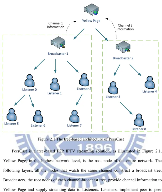
In PeerCast, data and routing information are transmitted through PeerCast Protocol (PCP) which is an application-layer protocol above TCP/UDP. The transport-layer protocol used in the current PeerCast system is TCP. There are three components in the PeerCast system, which are Yellow Page, Broadcaster, and Listener [2]. Yellow Page, has routing information for all channels, manages all channel information in PeerCast system and publishes this information in a web page. The Broadcaster, as a data source of each channel, can forward the encoded streaming data to clients in the PeerCast network. Listeners, as the peer users, download media stream from Broadcasters or other listeners and forward their own data to one or more additional listeners.
15
PeerCast is a tree-based P2P IPTV streaming solution, as illustrated in Figure 2.1. Yellow Page, in the highest network level, is the root node of the entire network. The following layers, all the nodes that watch the same channel construct a broadcast tree. Broadcasters, the root nodes of each channel-broadcast tree, provide channel information to Yellow Page and supply streaming data to Listeners. Listeners, implement peer to peer technology, not only receive but also forward data to other listeners. The Listener in the leaf of the broadcast tree doesn’t contribute any resources itself, and this is the main drawback of tree-based P2P streaming system.
Yellow Page Broadcaster 1 Listener 0 Listener 1 Broadcaster 2 Listener 2
Listener 5 Listener 6 Listener 7
Listener 4 Listener 3 Listener 8 Channel 1 information Channel 2 information
16
2.1.3. Operating Procedure
At the beginning, the listener selects a channel from web page of Yellow Page and query channel routing information. According to the routing table and routing algorithm, Yellow Page returns some channel sources to the listener. Next, the Listener establishes a network connection to one of those channel sources, perhaps it is a Broadcaster, and starts to download the media stream. If the max connection number of the Broadcaster doesn’t meet its upper bound, the Broadcaster adds that Listener to its list of child nodes and starts to transmit data stream after successful handshake. On the other hand, if the max connection number of the Broadcaster reaches its upper bound, the Listener cannot be served by the Broadcaster. After successful handshake, the Broadcaster selects up to eight its child nodes based on some algorithm to the Listener, and that Listener use these nodes as his parent node for receiving data stream [21].
2.1.4. Defects of PeerCast
Due to pure tree-based overlay, additional connection-maintaining messages are not needed in PeerCast. However, major drawback in tree-push IPTV streaming system is their unbearable cost to peer churn. Once a peer leaves the IPTV system, the video transmission to all peers rooted that departure peer would be interrupted. In addition, as long as the video playback of parent node occurs pause, the playback delay of all child nodes in the subtree rooted that parent node would accumulate up. According to the above, the difference of playback time between each node in the PeerCast streaming system would very large. This result in P2P share ratio greatly reduced, because almost most of the content cached by peers is not the same [3].
17
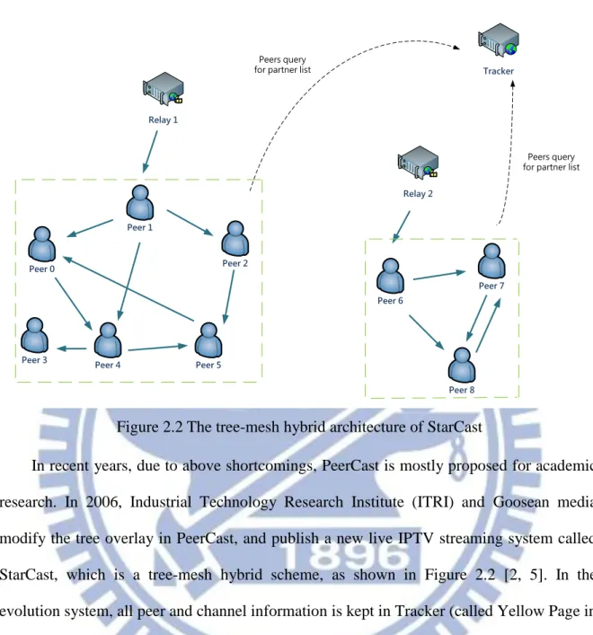
In recent years, due to above shortcomings, PeerCast is mostly proposed for academic research. In 2006, Industrial Technology Research Institute (ITRI) and Goosean media modify the tree overlay in PeerCast, and publish a new live IPTV streaming system called StarCast, which is a tree-mesh hybrid scheme, as shown in Figure 2.2 [2, 5]. In the evolution system, all peer and channel information is kept in Tracker (called Yellow Page in PeerCast) and the streaming data is transmitted by relay (called Broadcaster in PeerCast). Nowadays, there are many IPTV systems in the market, but most of these IPTV systems have a large amount of bandwidth consumption during viewers surfing period. On the other hand, these IPTV systems are lack of frame-type classification, and this result in additional playback delay due to the un-decoded video. We want to improve these shortcomings in our proposed scheme. In order to reduce the number of users’ surfing behavior, we discuss channel zapping behavior, channel zapping time and how to precisely choose the favorite channels of IPTV users.
Tracker Relay 1 Peer 0 Peer 1 Relay 2 Peer 2
Peer 3 Peer 4 Peer 5
Peer 7 Peer 6
Peer 8
Peers query for partner list
Peers query for partner list
18
2.2. Channel Zapping
2.2.1. Channel Zapping Behavior
The behavior of channel zapping can be classified into the following two categories: viewing channel and surfing channel. The viewer watches the same channel during a long period of time without zapping to others, called viewing behavior. The viewer searches the channel that he is interested in through random switching to other channels frequently in a very short time, which is called surfing behavior [4].
The viewer makes use of surfing behavior just to find his favorite programs, but this result in a great burden of the entire IPTV streaming system, whether on tracker loading or server-side bandwidth usage. As far as the streaming system is concerned, surfing behavior is just noise. The viewer doesn’t stay in that channel, but switch to other channel immediately.
In our proposed method, we not only want to improve the quality of experience under user’s viewing behavior, but also reduce the occurrence frequency of such surfing behavior, and further save the system bandwidth for other purpose.
2.2.2. Channel Zapping Time
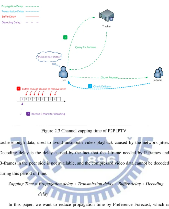
This period of time, the viewer chooses another channel which is not available in the client to play until he watches the display of the selected channel, is called channel zapping time. Channel zapping time is divided into four parts; they are propagation delay, transmission delay, buffer delay, and decoding delay respectively, as shown in Figure 2.3 [6]. Propagation delay is the time of control message propagation after the viewer switches to another channel. Transmission delay, caused by the data rate of the link, is the amount of time required to push all of the packet's bits into the wire. Buffer delay, the buffer has to
19
cache enough data, used to avoid unsmooth video playback caused by the network jitter. Decoding delay is the delay caused by the fact that the I-frame needed by P-frames and B-frames in the peer side is not available, and the compressed video data cannot be decoded during this period of time.
Zapping Time = Propagation delay + Transmission delay + Buffer delay + Decoding delay
In this paper, we want to reduce propagation time by Preference Forecast, which is mentioned in the following sections. We also cut down the decoding time by Reverse Pull, which is a key-frame first mechanism in the application layer.
2.2.3. Favorite Channel Selection Mechanism
In order to select the favorite channels for users, we have to collect broadcast
User Partners
Switch to other channel
Tracker
Query for Partners
Chunk Request 1
Chunk Delivery
2
I B B P B B B B
Buffer enough chunks to remove Jitter 3
Receive I-chunk for decoding
4
Propagation Delay: Transmission Delay:
Buffer Delay:
Decoding Delay:
20
popularity for each channel. There are two guides of channel selection: (1) User Preference and (2) Channel Preference. User Preference refers to which channels most likely to be selected for individual users. The most commonly used method is to use the tracker to get this data. Tracker records the viewer watching frequency of each channel, and selects the channels that the viewer most frequently watches as the viewer’s favorite channels [4].
Channel Preference refers to which channels that all viewers watch more frequently in the IPTV streaming system. To get Channel Preference information, tracker can be used to record each program’s broadcast popularity of all channels. In the IPTV streaming system, tracker can know the fact that which program that the user watches in specific time period. Tracker calculates the broadcast popularity of all channels through the times of user query for channel information during a specific period of time. In our proposed scheme, we use User Preference and Channel Preference to select the favorite channels and use these channels to lower the user surfing behavior.
In addition, there is no frame classification and prioritized chunk delivery mechanism in existing IPTV system. All audio and video clips are treated equally without discrimination, and this result in a poor video playback experience of client users. In the next section, we introduce some commonly used methods of frame classification and prioritized delivery in the past few years.
2.3. Frame Classification and Prioritized Delivery
Nowadays, there have been several research projects on frame classification and prioritized delivery [7, 8, 9, 10, 11, and 14]. There are three major types of frames (or pictures) used in video compression: I-frames, P-frames, and B-frames. Each I-frame is least compressible but can be encoded independently. P-frames, can use data from previous frames for data reference, does not need to store the unchanging background pixels. B-frames are encoded based on both previous and following frames to get the highest
21
amount of data compression. Typical MPEG encoded video utilizes a Group of Pictures (GOP) structure which specifies the arrangement of I, P, and B. Size-wise I-frames typically occupy 40% of the bandwidth share with remaining 60% being used by the P and B frames [12]. As their number is also lower, it can be concluded that an I-frame uses approximately ten times the number of transport units or IP packets used by a B-frame or P-frame. However their importance is very high. Current solutions such as proposed packet drop priority schemes for MPEG video streams [13]. This scheme introduced multiple levels of drop precedence for packets that belong to different frame types. Thus, when congestion occurs, packets from B-frames are more likely to be discarded than packets from P-frames. Similarly, P-frame packets would be dropped first when comparing to packets belonging to I-frames.
22
3. Proposed Scheme
In this session we describe the design principle and implement Preference Forecast and Reverse Pull. We consider large-scale mesh P2P systems for the distribution of the real-time video content. Our goal is to avoid burst request storm to tracker and reduce channel zapping time by Preference Forecast. In addition, we propose a new delivery scheme integrated with a new chunk-selected strategy to improve the QoS of playback smoothness, called Reverse Pull which leads to the satisfactory QoE of the user ends.
3.1. System Overview
Traditional television delivers signal using satellite, terrestrial and cable formats. It is always deployed by corporation and syndicate due to the facilities of the technology is too expensive for general population. Nevertheless the services of IPTV are delivered using Internet Protocol suite over a packet-switched IP network such as the Internet. IPTV can provide variable services to cater for the users with their different requirements. The residential users can access and distribute the IPTV services easily.
3.1.1. Encode
After source media content from satellite, cable, or terrestrial has gained by headend and passed through the media encoder, such as VideoLAN Client (VLC) [26] or Flash Media Server (FMS) [27], the media data is encapsulated and transmitted as a series of pictures or frames/slices, usually at a rate of 25-60 frames per second (fps). After that, these frames are sent to relays and divide into small chunks in high definition video. In order to shorten the decoding time of the channel zap, the key-frame chunks must have higher
23
priority for distribution in P2P IPTV network then the others. If a client receives video chunks in keyframe first, not only the user can gain an acceptable basic quality, but also the chunk can be decoded without reference to any other chunks. This shorten the decode time of channel zapping and saves the bandwidth of transmitting the chunks that can’t be decoded by itself.
3.1.2. Content Source
Relays obtain the encoded media data from headend and divided the data into chunks for P2P data distribution. In our proposed scheme, relays have to produce Snapshot Map and Key-Frame Map through encoded chunks and do “Snapshot Map Chat” and “Key-Frame Map Chat” (be mentioned below) with peers. Next, relays spread these media chunks to their own superseeds. Relays and superseeds are the original content sources for peers. When the peer who is the first viewer entering the IPTV system, he can only receive the media chunks from relays and superseeds. In order to implement Preference Forecast, the relay should collect the information of all its own superseeds that are responsible for the same channel and then put this data into a Superseed Bank. At the beginning of watching TV in the P2P IPTV system, the relay sends the Seed Table (subset of Superseed Bank) to the viewers, and this table is used for viewers to fast switch to another favorite channel without query to tracker.
When a new user comes into the IPTV system and starts to watch TV, he receives the media content from the relays and superseeds of his current watched channel. In the meanwhile, he also obtains the snapshots (low quality pictures to let users know the playing content of favorite channel) and Seed Tables through the relays’ notification.
3.1.3. Partner Selection
24
peers who establish a partner relationship with that user. Partner selection is reasonable for finding the peers to serve the video segments in IPTV system. The number of partners can’t be too large (in PeerCast, the number of partners is 8) in order to reduce the overhead in the peer side and tracker should find the best subset partners for users from the peers who watch the same channel. Users get the chunks out of frosting and gain full media quality by choosing appropriate partners. However, if partners have poor upload capacity, the user freezes the playback video by lack of chunks.
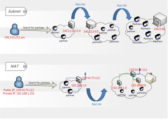
We choose the partners whose IP addresses are nearby the user by longest prefix match. An IP address of IPv4 can be represented by a 32-bit string and an IPv6 address can be represented by a 64-bit string. The longest prefix match between two IP addresses is the maximum number of prefix bits which are equal in the two IP addresses [25]. The tracker should parse the IP address of each partner and determine which partners have the longest
140.113.215.xxx partners partners partner partner 140.113.0.0 Partners Partners 140.0.0.0 Partners Partners Partners partner Subnet NAT Public IP: 229.54.75.112 Private IP: 192.168.1.251 partner partner 140.113.215.0 partner partner 192.168.1.0 229.54.75.112 192.168.1.0 192.168.0.0 partners partner partner 229.54.75.112 Search for partners
Search for partners
Not Hit
Not Hit Not Hit
25
prefix match with the user’s IP address. Through longest prefix match, the user has high opportunity to get the partners whose addresses belong to the same network domain with the user and obtains the partners with the user’s domain hierarchically, as illustrated in Figure 3.1. On the other hand, we pay attention to network address translation (NAT). Tracker has to additionally record the private IP of the peers behind a NAT-based router. If the partner’s public IP address is equal to the user, the tracker should send private IP address of this partner to the user to let him know how to search out his partner behind the NAT.
New incoming users or the channels zapping users usually have rare video segments before their playback deadline. For this reason, the tracker server should elect the peers who have large upload bandwidth to be the partners for these users (i.e., relays and superseeds).
In our configuration, we design a policy to give the urgent request higher priority to get the support of server (relays and superseeds). Let
U
denote the urgency coefficient andSPC
indicate server partner constant and the urgent requests are shown as follows:1. Request of the new incoming peer (n) 2. Request of channel zapping peer (z)
3. Request of the peer that has fewer chunks in cache before its playback deadline (f) The policy is:
IF peer is new incoming peer U = U * n
ELSE IF peer is channel zapping peer U = U * z
ELSE IF peer lacks of chunks in cache U = U * f
ELSE
26
IF U is greater than SPC
relays and superseeds are added into partner list;
ELSE
Normal peers are added into partner list;
The requests of the peers who have fewer chunks to stream out will be categorized to urgent request and get higher urgency coefficient. In this way, relays or superseeds have higher probability to become the partners of urgent-request peers. First of all, tracker sets
SPC
, and wrights (i.e., n, z, f) for partner selection. Next, tracker checks one by one to determine if the peers meet each of the above conditions, and then adjustsU
along with a variety of situations. At last, ifU
is greater thanSPC
, relays and superseeds can be added into partner list to supply smooth chunk transmission. On the other hand, those peers who watch the IPTV smoothly just use normal peers as partners, so the share rate of the P2P system can be improved.In Preference Forecast, peers get snapshots of favorite channels and the snapshots come with a Seed Table. Peers can gain Seed Table from the relay of favorite channel. However, if the peer gets the first snapshot from the other peer instead of relays, he gets the Seed Table from that peer. When the user switches to those favorite channels, the superseeds in the Seed Table become partners of that user. Therefore, user can get partner list without querying to tracker when he switch his favorite channels, and gain chunks smoothly by superseeds’ transmission.
3.1.4. Data Exchange
Transmission Control Protocol (TCP) provides a reliable and congestion-aware transport. However, when a peer receives a large number of TCP requests, he may not have additional capacity to serve other TCP requests. IPTV service and other networking applications running on the same host may have extra difficulty of handling a large number
27
of TCP connections. Recently, we found that most of the IPTV streaming systems using UDP instead of TCP to carry IPTV traffic. UDP incurs much less connection overhead than TCP. However, IPTV applications must address how to react to packet loss, because the UDP datagrams may be dropped in the networks. The most popular strategy is to ignore the dropped UDP datagrams.
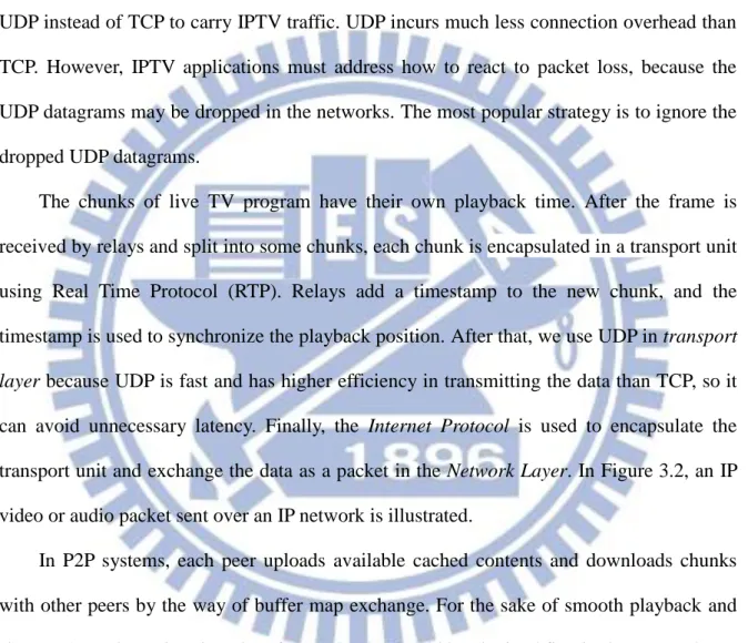
The chunks of live TV program have their own playback time. After the frame is received by relays and split into some chunks, each chunk is encapsulated in a transport unit using Real Time Protocol (RTP). Relays add a timestamp to the new chunk, and the timestamp is used to synchronize the playback position. After that, we use UDP in transport
layer because UDP is fast and has higher efficiency in transmitting the data than TCP, so it
can avoid unnecessary latency. Finally, the Internet Protocol is used to encapsulate the transport unit and exchange the data as a packet in the Network Layer. In Figure 3.2, an IP video or audio packet sent over an IP network is illustrated.
In P2P systems, each peer uploads available cached contents and downloads chunks with other peers by the way of buffer map exchange. For the sake of smooth playback and shorter channel zapping time, key-frame chunks should be obtained first in the user end. For this reason, we use Reverse Pull to accomplish keyframe first. Furthermore, we use Preference Forecast to curtail the channel zapping time and diminish the frequency of surfing channel when user begin to change to other channels. In Preference Forecast, client users receive snapshots of their favorite channels, so they can aware of their interesting television content every time and may not surf channels. A specially designed data structure
IP
Header
UDP
Header
RTP
Header
Video / Audio Payload
28
called Snapshot Map has been introduced to help peers sharing the snapshots for favorite channels. Peers can exchange snapshots with the peer who has the same favorite channel. Consequently, this may certainly diminish the loading of relays and superseeds.
3.1.5. Buffer
A video is segmented into media chunks and is made available for P2P distribution. A media chunk is the basic data unit of video stream in the P2P IPTV system. After producing chunks of the origin relays and receiving chunks from partner peers or superseeds, peers stores the retrieved chunks in a buffer. In P2P IPTV system, relays, superseeds and peers advertise buffer maps to each other for exchanging the availability of the chunks that they have cached.
In order to reduce the channel zapping time and avoid burst request storm to the tracker, we also introduce the concept of Preference Forecast. In Preference Forecast, relays and superseeds send some low quality snapshots to peers, and the snapshots going along with a Seed Table. This Seed Table is used to reduce channel zapping time through pre-fill partner lists by the superseeds of that favorite channel. Thanks to the additional pre-streaming snapshots, we should add additional buffers to the peer sides, called Preference Forecast Buffer (PFB). The number of the PFBs is equal to the number of the favorite channels. We can choose the favorite channels by user preference, channel preference [4], or set by the user.
Besides buffer map, in order to share snapshots with other peers, we introduce Snapshot Map to record the availability of snapshots. If the peer gets a snapshot, he should modify his own Snapshot Map. Then the peer advertises Snapshot Map to his partners in the p2p network. On the other hand, in order to implement Reverse Pull in our proposed configuration, we employ Key-Frame Map used to highlight the chunks which contain
29
I-frames or parts of I-frames. Key-Frame Map is produced by relays and indicates the existence of the chunks related to I-frames. The value of each item in the Key-Frame Map is set to “1” if the cached chunk references to I-frame, otherwise the value is set to “0”. Furthermore, the IPTV streaming system uses this data structure to raise the distribution priority of the chunks that are relevant to I-frames. In our configuration, the buffers and buffer maps utilized by the peers for chunk exchange and snapshot distribution are illustrated in Figure 3.3.
3.1.6. Decode
Video decoding delay is caused by the fact that compressed video content can’t be decoded by itself without I-frames, leads to playback freezing event, and this kind of delay
· PFB: Preference Forecast Buffer
cache
...
... ...
Buffer for current watched channel
... ...
PFB for favorite channel 1
... ...
PFB for favorite channel 2
... ...
PFB for favorite channel n
1 11 1
... 0 01 1 0 1 0 0 ...
Buffer Map (current watch)
1 00 0
... 0 01 0 0 0 0 0 ...
Key-Frame Map for Reverse Pull
1 00 0
... 0 0 1 0 0 00 0 ...
Snapshot Map for PFB 1
...
1 00 0
... 0 0 1 0 0 00 0 ...
Snapshot Map for PFB n
Peer
30
will be greatly removed in our system owing to I-frames always have high transmission priority by peers before the P-frames and B-frames by Reverse Pull. Therefore, when the peer get enough chunks to remove the unsmooth display caused by the delay jitter over the internet, decoder in the peer side can work correctly without additional delay. On the other hand, key frame first can also economize the use of bandwidth without transmission of the chunks that can’t be self-decoded and propose a satisfied QoE to the IPTV users.
3.2. Policy Design
3.2.1. Preference Forecast
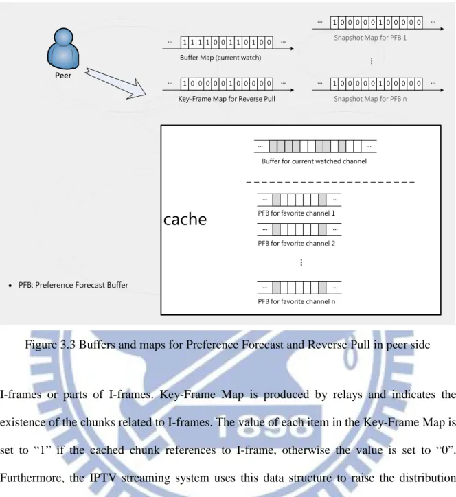
Popular programs, like CCTV New Year’s Gala, has gathered extremely large number of viewers. In PPS, the estimated number of the viewers watching that program at the same time is over 3 million people [24]. After these kinds of programs have been finished, there are excessively large number of viewer would switch their current watched channel to another one. This phenomenon results from burst request storm to the tracker in P2P IPTV architecture and can cause the whole P2P IPTV system crash. To solve this problem, in our proposed scheme, we introduce Preference Forecast to reduce the tracker burden and reduce channel zapping time furthermore.
In Preference Forecast, the relay for a specific channel in the P2P IPTV infrastructure gathers information of all superseeds which serve the same channel and deposits these supuerseeds’ information into a Superseed Bank. When the viewer starts to watch TV, the relays of his favorite channels get the IP address of that viewer and select suitable superseeds from each individual Superseed Bank. Relay picks superseeds into a Seed Table by the concept of the nearest superseeds. As mentioned above in partner selection, longest prefix match is applied in seed selection. Relays pick out the superseeds whose IP addresses
31
have the longest prefix match with the viewer’s IP address. Because the churn rate of superseeds is much lower than peers, relays usually do not need to choose so many superseeds like the number of partners. As illustrated in Figure 3.4, a hierarchical seed selection strategy by longest prefix match is introduced to superseed selection. Next, the relay of that favorite channel delivers the Seed Table with snapshots to that viewer.
Seed Tables are used for channel zapping in Preference Forecast. When the viewer isn’t interested in the current TV program and switches to his favorite channels, these Seed Tables can shorten the channel zapping time. Superseeds of the Seed Table can be used as P2P partners at beginning of channel zapping. As a result, viewers can get partners for chunk request from sending partner query to tracker and can save a round-trip time to get the video chunks. Because the superseeds usually have a larger bandwidth, the viewer use superseeds for his P2P partners can usually gain the video chunks earlier than normal peers.
Relay (CH36) Peer Superseed 1 (CH36) Superseed 2 (CH36) Superseed n (CH36) ...
Superseed 1 Superseed 2 ... Superseed n
Superseed Bank
140.113.215.215
...
Superseed 2 (140.113.215.225)
Superseed 2 Superseed 5 Superseed 7 …
Seed Table Prefer CH36
Send to peer 10001100.01110001.11010111.11010111 Superseed 5 (140.113.179.197) Superseed 7 (140.114.128.111) 10001100.01110001.11010111.11010111 10001100.01110001.11010111.11100001 10001100.01110001.11010111.11010111 10001100.01110001.10110011.11000101 10001100.01110001.11010111.11010111 10001100.01110010.10000000.01101111 Match 26 bits Match 17 bits Match 14 bits
32
During the period of the viewer receives the chunks of the channel that the viewer switches to, the viewer updates his partner list with the partners of that superseed and the following data exchange returns to peer to peer technology.
In user’s channel selection behavior of traditional TV, viewers might casually surf the channels by up/down button or numerical button to find an interesting program. In P2P IPTV system, this might seriously increase the tracker burden and transmits a lot of video chunks which the viewers are not interested with big bandwidth consumption. This period of time when the user surfs the channels is called “surfing time”. We try to reduce the user surfing time by snapshots of Preference Forecast in our proposed method.
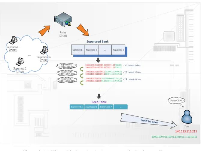
Snapshots are poor quality pictures which can let the viewer know the playing content of his favorite channels. In Preference Forecast, Snapshots of the favorite channel are delivered in advance to the viewers who are interesting in that channel. The peer may update a snapshot every other I-frame chunks or may receive a snapshot over a long period of time (maybe 1 or 2 seconds), as long as the viewer is aware of what the favorite channel is playing. Through the snapshots, the viewer can be aware of the program of the channel currently playing, as shown in Figure 3.5. Therefore, viewers may not surf the channels very often and the number of surfing times during the channel zapping should be greatly reduced.
33
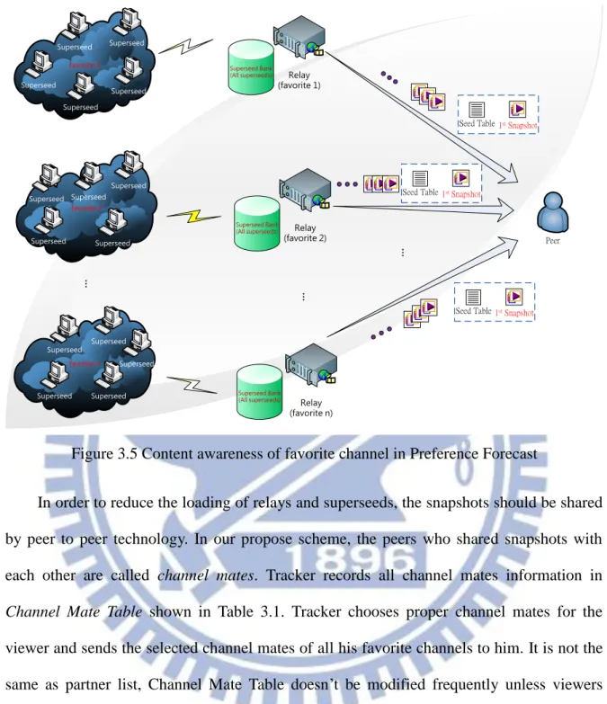
In order to reduce the loading of relays and superseeds, the snapshots should be shared by peer to peer technology. In our propose scheme, the peers who shared snapshots with each other are called channel mates. Tracker records all channel mates information in
Channel Mate Table shown in Table 3.1. Tracker chooses proper channel mates for the
viewer and sends the selected channel mates of all his favorite channels to him. It is not the same as partner list, Channel Mate Table doesn’t be modified frequently unless viewers change their favorite channels. Only when a new incoming viewer starts to watch TV or the user modifies his favorite channels, tracker should send the channel mates. Viewers employ channel mates and Snapshot Map to share snapshots with each other. In addition, if the viewer doesn’t connect to relay (i.e., relay is his channel mate), he gets seed table from other peers with snapshot transmission. The peer cache snapshots in PFB and record the fact that he has those snapshots in Snapshot Map. Through communicating by Snapshot Map
favorite n Superseed Superseed Superseed Superseed Superseed favorite 2 Superseed Superseed Superseed Superseed Superseed favorite 1 Relay (favorite 1) Relay (favorite 2) Relay (favorite n) ... ... Peer Superseed Superseed Superseed Superseed Superseed ... Superseed Bank (All superseeds) Superseed Bank (All superseeds) Superseed Bank (All superseeds)
Seed Table1st Snapshot
Seed Table1st Snapshot
Seed Table1st Snapshot
34
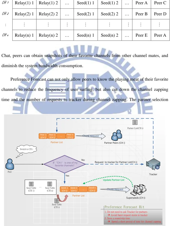
Chat, peers can obtain snapshots of their favorite channels from other channel mates, and diminish the system bandwidth consumption.
Preference Forecast can not only allow peers to know the playing meat of their favorite channels to reduce the frequency of user surfing, but also cut down the channel zapping time and the number of requests to tracker during channel zapping. The partner selection
Table 3.1 Channel Mate Table
CH 1 Relay(1) 1 Relay(1) 2 … Seed(1) 1 Seed(1) 2 … Peer A Peer C
CH 2 Relay(2) 1 Relay(2) 2 … Seed(2) 1 Seed(2) 2 … Peer B Peer D
… … … …
CH n Relay(n) 1 Relay(n) 2 … Seed(n) 1 Seed(n) 2 … Peer E Peer A
Tracker Chunk Request If “CH i” is one of my favorite channels? Yes Seed Table (CH 1) Seed Table (CH n) ... No Partner List(CH i)
Request to tracker for Partner List(CH i)
Peer Switch to CH i Seed Table (CH i) Seed 1 (CH i) Seed 2 (CH i) … Seed n (CH i) Partner List Peer 1 (CH i) Peer 2 (CH i) … Peer n (CH i)
Partner List Partner Peers (CH i)
Chunk Request
Preference Forecast Hit
1. Do not need to ask Tracker for partners à Avoid burst request storm to tracker 2. Save a round-trip time
à Spend a short period of time for channel zapping
Superseeds (CH i)
Update Partner List
35
mechanism of channel zapping in Preference Forecast is illustrated in Figure 3.6. If Preference Forecast not hit, users query to tracker for partners. If Preference Forecast hit, that is, users switch to their favorite channels, channel zapping time can be shorten by the local cached seed table of peers. Furthermore, the times of querying to tracker for user’s partner list should also be decreased.
3.2.2. Reverse Pull
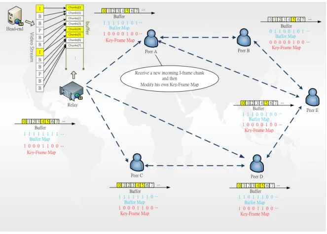
After receiving video stream from headend, relays encode the video stream into chunks for P2P distribution. These chunks are distributed over a self-organized mesh overlay. The current design of live P2P IPTV streaming systems is lack of differentiation among frame types. A loss of key-frame chunk may lead to severe video quality degradation. In order to avoid such a situation, we must distinguish key frames and then transmit them first by Key-Frame Map.
As depicted in the Figure 3.7, first, the headend delivers video stream to the relay. And then, the relay encodes the video stream into chunks and stores these chunks in his local buffer. Next, the relay modifies his buffer map and Key-Frame Map and begins to accept peers’ chunk requests. After the peer receive a new incoming chunk, he must determine whether this chunk is I-frame chunk or not and modifies his buffer map and Key-Frame Map.
Key-Frame Map can be used by peers to know which chunks are relevant to I-frames, so we can introduced this data structure to implement Reverse Pull. As shown in Figure 3.8, once the peer has gains a new incoming I-frame chunk, he modifies the buffer map and Key-Frame Map, and then advertises Reverse Pull message (RP message) to all his current partners to let them know that he has got a new I-frame chunk. After the partner of the RP
36 Head-end I B B P B B I B B P B B Chunks[6] Chunks[0] Chunks[1] Chunks[2] Chunks[3] Chunks[4] Chunks[5] Chunks[7] ... 01 234 56 7 11 111 11 1 10 001 10 0 Buffer Map ... 012 345 67 111 111 10 100 011 00 Buffer Map ... 0 123 456 7 1 101 110 0 1 000 110 0 Buffer Map ... 01 234 567 11 100 100 10 000 100 Buffer ... 012 345 67 100 001 00 Buffer Map ... 0 123 456 7 0 110 010 1 0 000 010 0 Buffer Map Key-Frame Map ... Key-Frame Map
Key-Frame Map Key-Frame Map
Key-Frame Map 111 101 01 Key-Frame Map Peer A Peer B Peer C Peer D Peer E b u ffe r V id eo S tr ea m
Receive a new incoming I-frame chunk and then
Modify his own Key-Frame Map Buffer Buffer Buffer Map Buffer Buffer Buffer ... ... ... ... ... ... ... ... ... ... ... ... Relay
Figure 3.7 Use Key-Frame Map to distinguish the I-frame chunks cached in peer side
Peer Buffer I-frame Chunks Normal Chunks None Cached 0000100 Buffer Map 1101110 Key-Frame Map ... ... Chunk [4] Chunk [3] Chunk [5] Chunk [6] Chunk [7] Chunk [8] Chunk [2] ... ... 2 1 3 Receive a new I-frame Chunk Partner A Partner B 4. RP 4. RP 0000000 Key-Frame Map ... ... 0000100 Key-Frame Map ... ...
Key-Frame Map Chat
Key-Frame Map Chat 5
5
· Does not have that I-frame chunk
· Send chunk request
· Already have that I-frame chunk · Ignore RP message
6 Chunk Request
... ...
37
sender receives that RP message, he depend on Key-Frame Map Chat to learn which I-frame chunk that the RP sender has and determine whether he has that I-frame chunk or not. If the partner peer doesn’t have that I-frame chunk, send chunk request to the RP sender for gaining that I-frame chunk. Otherwise, if he has that one, ignore the RP message.
On the other hand, if the playback point of a peer is much later than others, this peer may take a lot of I-frame chunks by keyframe first and does not have extra bandwidth to get P-frame chunks and B-frame chunks. This may lead to jumping, unsmooth and not coherent playback in the peer side. In order to prevent a large time difference between playback point of the peer and the chunk timestamp of the RP sender, if the I-frame chunk id of the RP sender is smaller than the playback chunk id of the peer, or the id difference between the I-frame chunk of RP sender and the playback chunk of the peer is more than client buffer size (i.e., does not need to request the chunk that will be used after a long period of time), the peer should ignore the RP message, as shown in Figure 3.9.
Reverse Pull is used to make the delivery of I-frame chunks with higher priority on chunk-based P2P live streaming system. Reverse Pull can also save system bandwidth from transmitting the chunks that can’t be decoded without reference to other chunks (i.e., P-frame chunks and B-frame chunks).Viewers can be aware of the video chunks that contain I-frames by Key-Frame Map in the system network and then through Reverse Pull to let the I-frame chunks sent to other peers earlier. Therefore, the decoding time of channel zapping would be reduced and the viewer doesn’t experience frequent freeze in the video playback.
38
3.3. Picture in Picture (PiP)
Picture in Picture (PiP) is a technology that enables viewers to watch multiple programs at the same time. In PiP, one program is broadcasted on the master window following one or more other subprograms are broadcasted in slave windows. High quality video stream is broadcasted on the master window for higher QoE of users. Due to the fact that the main purpose of the slave window is to let the viewer know the content that the favorite channel is being broadcasted now, only the low quality images are needed in slave windows. Audio usually accompanies the main channel playing in the master window only and the other subprograms in the slave windows are mute. In Figure 3.10, we inject Preference Forecast and Reverse Pull into Picture in Picture (PiP). Snapshots of favorite channels would come out whenever the user moves the cursor onto our designed PiP player, as illustrated in
Peer A Peer C Peer B 32 33 34 35 36 37 38 Buffer Map ... 1 1 0 1 1 0 0 ... 0 0 0 0 1 0 0 Key-Frame Map ... ... ... ... Playback Point Get a new I-frame chunk RP RP Buffer 3 4 5 6 7 8 9 Buffer Map ... 1 1 0 1 1 1 0 ... 0 0 0 1 0 0 0 Key-Frame Map ... ... ... ... Playback Point Buffer Ignore RP Ignore RP |36 – 7| > Buffer Size Ignore RP Ignore RP 36 < 42 (playback) 41 42 43 44 45 46 47 Buffer Map ... 0 1 1 1 0 1 0 ... 0 1 0 0 0 0 0 Key-Frame Map ... ... ... ... Playback Point Buffer Buffer Size = 25
39
Figure 3.11. Besides, the Seed Table is delivered with the snapshot transmission through the relay of favorite channel in the slave window; other snapshots are shared and distributed by P2P in order to lower the burden on the system bandwidth.
Viewers can be aware of the content of their favorite channels by using PiP with Preference Forecast. Because the favorite channels of the viewer are displayed in the slave windows, the viewer do not surf channels very often to find the programs he is interested in. The frequency of users’ surfing behavior would be reduced by means of PiP accompanied with Preference Forecast, and this would save a lot of bandwidth for the peers who have fewer chunks for playback. Because the Seed Tables of those channels already exist when the first snapshots are received, the channel zapping time would be shorten by one round-trip time if the zapping channel just hits one of those favorite channels. As a Result, peers can switch to their interesting channels without spending time surfing channels and
X _
+
-Advertisement Area
In Preference Forecast, Relays deliver Seed Table with snapshot transmission and the other
snapshots are transmitted by P2P to salve windows!
Close Restore Down
Minimize Full Screen (Enter)
Down Up Stop Pause Play Volume
Main Program use
Reverse Pull in chunk scheduling Poor quality subprograms are broadcasted in slave windows (Video only) Full quality main program (Video and Audio)
40
get the partner lists of zapping channels by local Seed Tables without querying to tracker. This would reduce the probability of burst request storm to tracker.
High quality main program is displayed in master window of the PiP player. In attempt to achieve higher QoE, chunk scheduling of the main program uses Reverse Pull to ensure that the peers watch the video continuously without freezing the playback. By the means of PiP accompanied with Reverse Pull, the peers have higher probability to get the chunks related to key-frame before its playback deadline. As a result, it not only can reduce the decoding time of channel zapping, but also has no stagnant playback in the user side.
Favorite channel will come out when moving cursor on the PiP
Player
X _
+
41
4. Simulation Scenario
The performance of the proposed scheme is to demonstrate the improvement of Preference Forecast and Reverse Pull compared with the original tree-mesh hybrid IPTV system like StarCast in simulation by OMNeT++. OMNeT++ (Objective Modular Network Testbed in C++), based on discrete event, is an object-based, free, open-architecture and modular simulation platform. It plays a very important role in network simulation and becomes more popular in recent years. We can implement C++ program by using the library it provides. In addition, the graphical runtime environment can be designed according the style of every programmer, which eases the difficulty of debugging. Therefore, OMNeT++ is very suitable for implementation of P2P live streaming service.
4.1. Experiment Setup
4.1.1. Roles on System Overlay
Preference Forecast and Reverse Pull are applied on a tree-mesh hybrid P2P streaming system, which consists of trackers, relays, superseeds, and peers on P2P overlay. Tracker is responsible for channel watching information of all peers. Relays are used to produce the media chunks, Snapshot Map, and Key-Frame Map. Superseeds have to share the chunks distribution of relays. As shown in Figure 4.1, there are one tracker, 10 relays, 20 superseeds, and 30 peers.
42
4.1.2. The Design and Operation of System Modules
In Preference Forecast, in order to delivery snapshots, we introduced some new design data structures, as shown in Figure 4.2. The new design data structures in our proposed scheme are Channel Mate Table, Channel Mate List, Superseed Bank, and Seed Table.
According to Channel Mate Table which is cached in tracker, viewers know which peers are his channel mates. In peer side, Channel Mate List is responsible for snapshots sharing. Superseed Bank, cached in a relay, has all information of superseeds serving the same channel with the relay. Seed Tables, selected by relays, are used as partners of peers during channel zapping.
43
Preference Forecast, as illustrated in Figure 4.3, the viewer starts to watch TV and query to tracker for partners and channel mates. Next, the viewer uses Snapshot Map Chat to know which snapshots are available in the PFB of that channel mate and sends snapshot request. If the channel mate is a relay, he has to select a Seed Table from his Superseed Bank and sends the Seed Table to the viewer. On the other hand, if the channel mate is just a peer, he only needs to send his Seed Table to the viewer with snapshot transmission. When the viewer switches to another channel, the client program embedded Preference Forecast has to check if the objective channel is one of favorite channels of the viewer. If so, the viewer uses the superseeds in the Seed Table as his partners of objective channel at the beginning, and next, his chunk sharing returns to P2P technology through the mechanism which refreshes the partner list by using partners of the superseed. If not, the viewer has to query partner list of that objective channel.
Tracker Relay CH i CH 1 CH 2 … CH 100
Seed 1 Seed 2 Peer A Seed 1 Seed 2 Seed 1 Seed 2 Seed 1 Seed 2 Peer B Peer C Peer D Peer C Peer A Peer D Peer E Relay 1 Relay 2 Relay 1 Relay 2 Relay 1 Relay 2 Relay 1 Relay 2 … … … … … … … … … … … … Channel Mate Table
CH 1 CH 2
…
CH 100
Seed 1 Seed 2 Peer A Seed 1 Seed 2 Seed 1 Seed 2 Seed 1 Seed 2 Peer C Peer E Peer G Peer B Peer D Peer F Peer H Relay 1 Relay 2 Relay 1 Relay 2 Relay 1 Relay 2 Relay 1 Relay 2 … … … … … … … … … … … … Partner Table
CH i Seed 1 Seed 2 … Seed n
Superseed Bank
Peer
Seed 2 Seed 3 Seed 5
Seed Table Master Window For c hunk shar ing Slave Window For snap shot s shar ing
Channel Mate List Partner List
For channel zapping
44
Reverse Pull, as illustrated in Figure 4.4 and 4.5, the viewer continuously receives chunks from partners. Once the peer receivers a chunk, he determines whether the chunk is
Relay of CH i send Seed Table with 1st snapshot to viewer Viewer get Seed Table (only once)
& snapshots from channel mates
Relay of CH i collects all its Superseeds info into a
Superseed Bank
Relay of CH i select suitable Superseeds for viewer into a
Seed Table Viewer starts to watch TV and one
of his favorite channel is CH i
Viewer query to tracker for partners(current watch) and
channel mates(favorite channel) Relay of CH i receives snapshot request of viewer
Relay of CH i produce snapshots continuously
Viewer sends snapshot request to channel mates
(Relay, Superseed, Peer)
Viewer switch to CH j
If CH j is favorite CH of the viewer
Use superseed in the Seed Table as his partner
Send chunk request to superseed
Superseed update his partner list to the viewer
Yes
Query partners to Tracker No
Peer
Relay
Snapshot Map Chat
45
I-frame chunk or not. If so, the viewer broadcasts RP message to his partners. If not, he continues to download the chunks that he doesn’t have. After the peer receives the RP message, he checks (1) whether he has that I-frame chunk or not (2) if the difference between I-frame chunk ID and playback point of the peer is greater than client buffer size and (3) if I-frame chunk ID is less than playback point of the peer. If one of the answers is “Yes”, the peer ignores the RP message. Otherwise, if all answers are “No”, the peer sends chunk request to the RP sender for that I-frame chunk.
Viewer select channel i to watch
Viewer Query to tracker for Partner list
Viewer Send chunk request to partner (Relay, Superseed, or Peer)
Viewer receives chunks from partner
Is the receiving chunk I-frame chunk?
Broadcast RP to partners Yes
No
Key-Frame Map Chat
RP Sender
46
4.2. Experimental Precondition
In the simulation, there are 2~100 channels, 1 tracker, 2~100 relays (the same as channel number), 10~500 superseeds (assume one relay has 5 superseeds), and 2000~20000 peers. Each peer has eight partners. The video stream encoding structure is “IBBPBB” GOP structure. The upload bandwidth of the tracker, relays, and superseeds are all set to 6
Receive RP Message
K-Frame Map Chat
I have that I-frame chunk ?
Ignore RP I-frame chunk ID – my
playback point > Client Buffer Size ? Yes
Continue to download other chunks No Yes No I-frame chunk ID < my playback point? Yes No
Send chunk request to the RP sender