A Petri-net-based structure for AS /RS operation modelling S. HSIEH² *, J.-S. HWANG² and H.-C. CHOU²
This paper presents a Petri-net (PN)-based hierarchical structure for AS/RS operation modelling. The complete AS/RS operation is modelled by four di erent layer modules, including the command typing layer (CTL), the command pro® le layer (CPL), the command compilation layer (CCL)and the command execution layer (CEL). To simplify the structure, macro-places are created to represent complicated activities associated with some speci® c groups of functions. The complete modelling system is implemented in a compact `Visual C’-based object-oriented computer program. The `click’ function is introduced to allow macro-places to be zoomed in for detailed internal activity visualization. In a typical AS/RS, operation commands are generated and issued by the manage-ment system. Each command is ® rst typed and queued in the CTL module and then delivered one by one to the CPL module for work-domain (i.e. the starting and ending locations of the crane)evaluation. After the work-domain is decided, the information is delivered to the CCL module for command sequence compila-tion. The compiled command sequence is then executed in the CEL module by the crane device. By employing the proposed four-layer modelling procedure, basic AS/RS operation modules of any size can be developed and then assembled to construct a complete AS/RS-PN model. By carefully analysing the properties of the complete AS/RS-PN model, the robustness of the AS/RS structure is veri® ed.
1. Introduction
Automated storage/retrieval systems (AS/RSs
)
are of great current interest due to many attractive bene® ts, e.g. lower cost of building and land, saving of labour, reduction of inventory levels, improvement of material tracking and higher system throughput. Once the system is installed and operated, the measurable bene® t of an AS/RS is predominantly dependent on the control policies used. The control policy of an AS/RS is usually application-dependent and dynamic. To e ectively operate an AS/RS, system simulations are often required to determine the best control policies. Thus, we seek ways to e ciently build simulation models for AS/RSs.The control policies that determine the performance of an AS/RS have been studied by many researchers. Prior research has focused on the crane travel time. Bozer and White (1984
)
developed travel-time models that can be used to establish throughput standards for existing systems and evaluate the design con® guration for new systems. Hwang and Lee (1990)
presented a travel-time model that considered the operating characteristics of the stacker crane, including acceleration, deceleration and the maximum velocity restriction. Chang et al. (1995)
proposed a travel-time model that considered various travel speeds with known acceleration/deceleration rates. Egbelu (1991)
improved the system performance by dynamically determining0020± 7543/98 $12.00Ñ 1998 Taylor & Francis Ltd.
Revision received January 1998.
² Department of Mechanical Engineering, National Taiwan University, Taipei, Taiwan
10764, Republic of China.
the dwell point of the stacker crane. Randhawa and Shro (1995
)
pointed out that the system performance measures are a ected by the design speci® cation of an AS/RS. A simulation model was developed to evaluate several design speci® cations. Despite the success of these studies, a comprehensive AS/RS simulation model has not yet been established since optimal control policies are dynamic and basic AS/ RS operational modules common to all applications do not exist. In the study of the crane operation, it is found that the crane operation is quite basic and common to all applications. If the crane operation can be modelled in advance, the simulation model can be constructed with ease by combining the basic operational modules and the main control model.
Petri-nets (PNs
)
have been adopted as a general tool for modelling the operation of manufacturing systems in recent years (Moore and Gupta 1996)
. Archetti et al. (1991)
adopted PN models and a stochastic optimization method to study optimal control policies of an AS/RS. Knapp and Wang (1992)
and Lin and Wang (1995)
used stochastic PNs (SPNs
)
to model AS/RS. A PN graph of an AS/RS leads to the generation of a reachability table that can be converted to a state representation of a Markov process model of the AS/RS. The e ciency, control rules, bay assignment and other performance issues can then be studied by using the SPN model. Chincholkar et al. (1994)
and Chincholkar and Chetty (1996)
adopted stochastic coloured PNs (SCPNs)
as a modelling and analysis tool to construct an AS/RS model. The in¯ uence of crane operation modes and scheduling policies on system performance was studied. The invariants were used to study the structural properties of the SCPNs. Zhou (1996)
presented a PN model for bu ers and a methodology to include bu ers in a system without introducing deadlocks or over¯ ows. D’Souza and Khator (1994)
, Jafari (1992)
, Sun et al. (1994)
and Zhou et al. (1993)
used PNs to model ¯ exible manufacturing cells/systems. Kazuo et al. (1993)
, Ramaswamy and Valavanis (1994)
and Moore and Gupta (1995)
proposed an extended PN model to analyse and simulate the material handling system. Although some excellent works in material ¯ ow modelling have been published, little e ort has been focused on the development of a generic AS/RS model structure.In a typical AS/RS of unit load type, the system can comprise rack structures, input/output bu er stations, crane machines, sub-system controllers and the main controller of the system. A crane is installed and performs loading/unloading tasks in the aisle following the command issued by the sub-system controller. The sub-system controller receives commands from the main controller. Let a crane, its left and right side racks, input/output bu er stations and the sub-system controller be treated as a set, called the `unit operation module’. Then, any complete unit load type AS/RS can be composed of n unit operation modules (n is the number of unit operation mod-ules
)
and a main controller. The control strategies may vary from one system to another. The number and size of unit operation modules may be di erent. The basic elements of a unit operation module are the same. The PN model of the unit opera-tion module for a general unit-load AS/RS can therefore be established in advance. By incorporating the pre-modelled unit operation modules and the main control model, an AS/RS model can be constructed.In this paper, we propose a PN based four-layer structure for the AS/RS. We focus on modelling the unit operation module using a modular concept. Our purpose is to establish a unit operation module for use in a general AS/RS model. With this unit operation module structure, the AS/RS model of any unit-load type can easily be obtained by assembling these modules. PNs are adopted as the modelling tool and
the object-oriented `Visual C++’ is used to generate PN graphs for detailed process visual veri® cation. A built-in `click’ function is adopted for zoom-re® nement that alllows a lower-level in-process model to be displayed in detail. To ensure the pro-posed four-layer structure is robust, structural properties are analysed.
2. Petri-net modelling
Petri-nets theory is a widely used tool for modelling complex systems of inter-acting concurrent components. The net theory allows a system to be represented by a mathematical model. Important information of the system concerning basic struc-tures and dynamic behaviours is well characterized by the net model. Thus, the model can be used for structural analysis and/or performance evaluation. Some de® nitions of PN structure are given (Peterson 1981, Murata 1989
)
as follows: De® nition 1: A PN structure, N, is a 4-tuple, N= (P,
T,
F,
G) where :(1
)
P={
p1,
p2,
. . .
,
pm}
is a ® nite set of places, m= 0;(2
)
T={
t1,
t2,
. . .
,
tn}
is a ® nite set of transitions, n= 0. P´ T=[ and = Ä T=/[ ;(3
)
FÍ
(P´
T) is a function from P to T, commonly known as an input func-tion;(4
)
GÍ
(T´
P) is a function from T to P, commonly known as an output function.De® nition 2: A marking ¹ of a PN is a function ¹ :P
®
Q, Q={
0,
1,
2,
. . .
}
, ¹i=¹(pi)Î
Q. In a system with m places, the mapping function ¹ consists of m elements that de® ne the state of the places and tokens at a particular time, ¹= (¹1,
¹2,
. . .
,
¹m), ¹i=¹(pi), piÎ
P. A PN structure N that contains a marking ¹ is marked PN. A marked PN is denoted by M= (N,
¹).The behaviour of dynamic systems can be described in terms of system states and their changes. In a dynamic system, a state or marking in a PN is changed according to the transition ® ring rules:
(1
)
a transition t is said to be enabled if each input place p of t is marked with at least w(p,
t) tokens, where w(p,
t) is the weight of the arc from p to t; (2)
an enabled transition may or may not ® re (depending on whether or not theevent actually takes place
)
;(3
)
a ® ring of an enabled transition t removes w(p,
t) tokens from each input place p of t and adds w(t,
p)tokens to each output place p of t, where w(t,
p) is the weight of the arc from t to p.An inhibitor arc is a directed arc from a place pi to a transition tj with a small
circle rather than an arrowhead at the transition. The small circle means `not’. The ® ring rule is given as follows: a transition is enabled when tokens are in all of its normal inputs and zero tokens are in all of its inhibitor inputs; the transition ® res by removing tokens from all of its normal inputs.
De® nition 3: For a PN structure, N, with n transitions and m places, the incidence matrix A=
[
aij]
is an n´
m matrix of integers and its typical entry is given bywhere a+ij =w(i
,
j) is the weight of the arc from transition i to its output place j anda-ij =w(i
,
j) is the weight of the arc to transition i from its input place j.De® nition 4: A marked graph (MG
)
is an ordinary PN, such that each place has exactly one input transition and exactly one output transition.2.1. Structural properties
The structural properties of a system can be characterized by the topological relation of PNs. They are independent of the initial marking M0 in the sense that
these properties hold for any initial marking or are concerned with the existence of certain ® ring sequences from some initial marking. Thus, these properties can often be characterized in terms of the incidence matrix and its associated homogeneous equations or inequalities (Murata 1989
)
. Some important structural properties are given by Murata as follows.(1
)
Structural liveness: a PN N is said to be structurally live if there exists a live initial marking for N. A MG is structurally live.(2
)
Controllability: a PN N is said to be completely controllable if any marking is reachable from any other marking. A MG is completely controllable i Rank A=m.(3
)
Conservativeness: A PN N is said to be (partially)
conservative if there exists a positive integer y(p) for every (some)
place p such that the weighted sum of tokens, MTy=M0Ty=a constant, for every MÎ
R(M0). A PN N is(par-tially
)
conservative i there exists an m-vector y if positive (non-negative)
integers such that Ay=0, y=/ 0.
(4
)
Repetitiveness: a PN N is said to be (partially)
repetitive if there exists a marking M0 and a ® ring sequences from M0 such that every (some)
transi-tion occurs in® nitely often ins . A PN N is repetitive i there exists an n-vector x of positive (non-negative
)
integers such that ATX³
0.(5
)
Consistency: a PN N is said to be (partially)
consistent if there exists a marking M0and a ® ring sequences from M0, such that every (some)
transi-tion occurs at least once ins . A PN N is consistent i there exists an n-vector x of positive (non-negative
)
integers such that ATx=0.3. AS /RS -PN operation model
As mentioned before, an AS/RS consists of several unit operation modules. Every module is independent from each other. Whenever a job is requested and issued by the AS/RS management system, one of the operation modules will receive the command and execute the job. Therefore, instead of dealing with the AS/RS operations as a whole, one can begin by constructing each unit operation module ® rst and then combining relevant unit operation modules with a management system to establish a complete AS/RS model.
An AS/RS crane usually executes task assignments in a ® xed area within the scope of a single unit operation module. All activities of a stacker crane can be described by a unit operation module. Therefore, in this paper we should focus on the detailed model structure of a basic unit operation module and the related struc-tural properties. The presentation focuses entirely on the structure of unit operation modules. The issues of scheduling policy, and the policies for operating and storage will not be addressed in this paper.
3.1. A hierarchical four-layer structure
Since a unit operation module comprises both the information ¯ ow component and the crane operation component, both components are required for a functional unit module. The tasks involved in the information ¯ ow component comprise the job request, destination location, current crane location, responses of sensors, and the crane status. The tasks involved in the crane operation components consist of the operations of storage, retrieval and homing. The storage task can be one of three di erent storage functions, including the function from rack to bu er and from bu er to rack, the function from bu er to rack, and the function from home to bu er, and then from bu er to rack. The retrieval operation also has three functions, including the function of rack± rack± bu er, the function of bu er± rack± bu er and the function of home± rack± bu er. The homing operation can be either a task from rack to home, or a task from bu er to home. The crane moves along the guidance path and loads/unloads parts from/to the rack and bu er. The crane returns to its home position once a homing command is executed. All of these activities are included in a basic unit operation model.
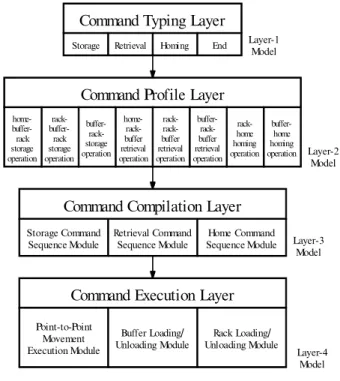
To simplify the model structure, macro functions are introduced and implemen-ted into the model. After a detailed study on the activities of a basic unit operation module, these activities are further classi® ed into four di erent hierarchical layers. The four-layer model is illustrated in ® gure 1 and is elaborated as follows.
(1
)
Command Typing L ayer (CTL)
: in this layer, the operation command embedded in the information ¯ ow issued by the top management system is received, decoded, typed and queued in sequence. Once the command is decoded and typed, an end command token is issued to the top management system. The typed command is passed to the next layer for the working domain search, sequence compilation and action execution. The type of commands that can be detected in CTL include storage, retrieval, homing and end.(2
)
Command Pro® le L ayer (CPL)
: the work domain (i.e. the starting and ending locations)
of a crane for each speci® c command is searched, and uniquely de® ned by the data of the current location and the end destination of the device.(3
)
Command Compilation L ayer (CCL)
: a sequence of crane actions that satisfy the requirement of a speci® c operation command is compiled and issued to the command execution layer.(4
)
Command Execution L ayer (CEL)
: in this layer, the physical actions of the crane device are carried out in sequence. These actions include the movement of a crane from its starting position to the end position and the performance of a part loading or unloading operation at a bu er station or rack. A macro place in a layer is used to represent some complicated activities associ-ated with a group of functions. A clicking on a macro place in the upper layer allows the user to bring up a re® ned structure and observe the activities in detail in the next lower layer. In order to do that, several conditions need to be satis® ed:(1
)
the input (output)
transitions of the next lower layer model are the input (output)
transitions of the upper-layer macro place;(2
)
The initial marking of the ® rst place in the next lower layer model is equiva-lent to the initial marking of the macro place in the upper layer model;(3
)
The ® nal marking of the last place in the next lower layer model is equivalent to the ® nal marking of the macro place in the upper layer model.To make the proposed PN model simple in structure, various shape places and tokens, as given in ® gure 2, are used to represent di erent physical conditions. Although these places and tokens may be di erent in shape, their PN de® nitions are the same. To further distinguish the crane operation procedures from the infor-mation command ¯ ow, solid and dashed lines are used to represent the directed arcs of crane operations and the information commands, respectively.
To ensure the robustness of the proposed architecture, the structural properties are analysed for each layer of the model. Structural properties, e.g. liveness, con-trollability, conservativeness, repetitiveness and consistency are characterized by incidence matrices.
3.2. Command typing layer
The CTL model, as shown in ® gure 3, is a layer model that possesses two ordinary places and one macro place. Ordinary places W and F represent the com-mand waiting state and the comcom-mand complete state, respectively. Since a comcom-mand operation macro place B1 is a kernel of the layer, it can be zoomed into the next layer for a re® ned pro® le picture. Transitions t00 and t03 could be transitions of a macro
place in the top management system model. They are involved with the management policies and therefore they will not be discussed in this paper.
3.2.1. Token movement rules in CTL
Once a job is requested, a corresponding command is issued to a speci® c unit operation module in the system. This is done by ® ring the transition t00 in the
Command Typing Layer
Storage Retrieval Homing End
Command Profile Layer home- buffer-rack storage operation rack- buffer-rack storage operation buffer- rack-storage operation home- rack-buffer retrieval operation rack-buffer retrieval operation buffer- rack-buffer retrieval operation rack-home homing operation buffer-home homing operation Retrieval Command
Sequence Module Sequence ModuleHome Command Storage Command Sequence Module Point-to-Point Movement Execution Module Buffer Loading/
Unloading Module Unloading ModuleRack Loading/ Layer-1 Model Layer-4 Model Layer-3 Model Layer-2 Model
Command Compilation Layer
Command Execution Layer
management system model. A corresponding operation command token for storage, retrieval or homing operation is deposited immediately into the place W. Since a unit operation module may receive several di erent commands from the top management system, the commands may stay in the waiting state and be queued in place W. Only one command can be executed at a time in a command operation macro place. The inhibitor arc from B1 to t01 is used to make sure at most one command token can
stay in the command operation macro place B1. Once the transition t01 is ® red, a
command token is deposited to the command operation macro place B1. The received command is executed. An end command token is ® nally deposited to the ordinary place F to signal the completion of one operation command event. A job completion message is sent to the management system by ® ring transition t03.
3.2.2. Structural properties of the CTL
The technique to analyse a net having an inhibitor arc is not currently available in literature. By eliminating the inhibitor arc, the CTL model becomes a MG. Di erent command types (i.e. storage, retrieval and homing
)
can best be representedOrdinary Place
Storage Command Place Storage Command Token
Retrieval Command Place Retrieval Command Token
Homing Command Token End Command Token Signal Token Homing Command Place
End Command Place Signal Place
Macro Place
Crane Device Token
Figure 2. Physical meanings for di erent shapes of places and tokens in the AS/RS opera-tional PN model. F W B1 t00 t02 t01 t03
Figure 3. The command typing layer model. (Note: t00 and t03 are the input and output
by tokens of di erent shapes. Using the coloured PNs presented by Jensen (1996
)
, the CTL model can be expressed in terms of a 7´
12 incidence matrix, which is given asW B1 F ACTL= t00 t01 t02 t03 1 0 0 0 0 0 0 0 1 0 0 0 0 0 0 0 1 0 0 0 0
-
1 0 0 1 0 0 0 0-
1 0 0 1 0 0 0 0-
1 0 0 1 0 0 0 0-
1 0 0 1 0 0 0 0-
1 0 1 0 0 0 0 0-
1 1 0 0 0 0 0 0-
1 0 0 0 0 0 0-
1 0 0 0 0 0 0-
1-From this incident matrix, one can easily deduce several key structural properties of the CTL.
(1
)
L iveness: since the source transition t00 is unconditionally enabled, the CTLmodel is live.
(2
)
Controllability: since the CTL model is a MG and rank(ACTL) =7, the CTLmode is completely controllable.
(3
)
Conservativeness: it is not required for the CTL to have this property. (4)
Repetitiveness: there exists a 12´
1 vector, x=[
1 1 1 1 1 1 1 1 1 1 1 1]
. Sincex is of positive integers and ACTLT x
³
0, the CTL model is structurallyrepe-titive.
(5
)
Consistency: there exists a 12´
1 vector, x=[
1 1 1 1 1 1 1 1 1 1 1 1]
. Since x is of positive integers and ACTLT x=0, the CTL model is structural consistent.3.3. Command pro® le layer
The CPL model possesses three types of function macros (i.e. storage, retrieval and homing
)
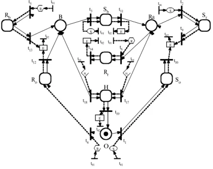
. Judging from the current location of the crane device, one can further classify a storage function macro into three operations of di erent work domains. They are the operation of home± bu er± rack, the operation of rack± bu er± rack and the operation of bu er± rack. Similarly, a retrieval function macro can also be classi-® ed into three operations of di erent work domains, i.e. the operation of home± rack± bu er, the operation of rack± rack± bu er and the operation of bu er± rack± bu er. However, a homing function macro can only be classi® ed into two operations of work domains including the operation of rack± home and the operation of bu er± home.Figure 4 shows a complete CPL model. This model is composed of a crane model (i.e. the portion where places are connected to each other by solid lines
)
and three di erent control loops (i.e. the portion where places are connected by dashed lines)
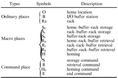
. A crane model indicates the current position of a crane and determines the workdomain of a possible operation. The starting address of an operation in the CPL is the current position of the crane. The path and end position of an operation com-mand are derived from one of eight possible transition operations. The ordinary places, O, Ra and B, stand for the physical positions of home, rack and bu er, respectively. The ordinary token in an ordinary place indicates the location of a crane device. The macro places, S, R and H, represent the storage operation macro, retrieval operation macro and homing operation macro, respectively. The subscripts, o, r and b attached to the macro places S and R, stand for the starting position at home, rack or bu er for each associated operation. The macro place H has two possible starting positions, at the bu er or rack.
As given in the CTL model of ® gure 3, when the transition t01 is ® red, a
com-mand token is deposited to the macro place B1. After the re® nement of macro place B1, the corresponding command token is moved directly into the CPL. When a job is completed, an end command token is generated in the CPL and then returned to the CTL. Figure 4 contains eight (three for storage, three for retrieval and two for homing
)
control loops that are used to convey the operation and the end command token from the CTL/CPL to the CPL/CTL. Besides transitions t01and t02, a storagecontrol loop comprises a storage command place, end command place and storage operation macro place. Similarly, a retrieval control loop comprises transitions t01
and t02, a retrieval command place, end command place and retrieval operation
macro place. A homing control loop comprises transitions t01 and t02, a homing
command place, end command place and homing operation macro place. The physi-cal meaning of each place in ® gure 4 is detailed in table 1.
3.3.1. Token Movement Rules in CPL
When a crane is idle, it can be at home, at a bu er or at a rack. An ordinary token residing in an ordinary place O indicates that the crane is at home. Once a job
Sb Rr H O Sr So Ra B Ro Rb t1 t2 t3 t4 t5 t6 t10 t9 t11 t12 t13 t14 t17 t18 t19 S S S R R R E E E E E Ho Ho t02 t02 t01 t01 t02 t01 t01 t02 t01 t01 t02 t01 t01
Figure 4. The command pro® le layer model. (Note: t01and t02are the input and output
request command is detected and zoomed into the CPL, an operation command token is deposited to the command place through the corresponding command con-trol loop. However, the crane device token remains at one of the ordinary places. When the job is completed, the crane stays where it was and the operation command token is removed from the operation macro place. An end command token is depos-ited to the end command place and then returned to the CTL through the control loop. A crane token is deposited to an ordinary place (O, B, or Ra
)
, where it waits for the next command. When a transition is ® red, the command token moves along the directed dashed arc and the crane token moves along the directed solid arc. 3.3.2. Structural Properties of the CPLThe structural analysis of the CPL model can be performed by checking the crane model, three control loops and the complete model, respectively.
3.3.2.1. The crane model and its structural properties. The incident matrix of a crane model is given as O Ra B S0 Sr Sb Ro Rr Rb H Acrane= t1 t2 t3 t4 t5 t6 t9 t10 t11 t12 t13 t14 t17 t18 t19
-
1 0 0 1 0 0 0 0 0 0 0-
1 0 0 1 0 0 0 0 0 0 0-
1 0 0 1 0 0 0 0-
1 0 0 0 0 0 1 0 0 0 0 0-
1 0 0 0 0 0 1 0 0-
1 0 0 0 0 0 1 0 0 0 1 0 0-
1 0 0 0 0 0 0 1 0-
1 0 0 0 0 0 0 0 1 0 0 0-
1 0 0 0 0 0 0 1 0 0 0-
1 0 0 0 0 0 1 0 0 0 0 0-
1 0 0 0 1 0 0 0 0-
1 0 0 0-
1 0 0 0 0 0 0 0 1 0 0-
1 0 0 0 0 0 0 1 1 0 0 0 0 0 0 0 0-
1Types Symbols Description
O home location
Ordinary places
{
B I/O bu er stationRa rack
S0 home± bu er± rack storage
Sr rack± bu er± rack storage
Macro places Sb bu er-rack storage
R0 home± rack± bu er retrieval
Rr rack± rack± bu er retrieval
Rb bu er± rack± bu er retrieval
{
H homingS storage command
Command place HR retrieval command
0 homing command
{
E end commandThe structural properties of the crane model are addressed as follows.
(1
)
L iveness: the crane model is a closed system. A crane token is always in the system. Since the crane token is in an ordinary place, O, Ra or B and the initial marking M0is equal to [1 0 0 0 0 0 0 0 0 0], [0 1 0 0 0 0 0 0 0 0], or[0 0 1 0 0 0 0 0 0 0], the net is live. Thus, the model is structurally live. (2
)
Controllability: since the crane model is not a MG, the completelycontrol-lable property canot be identi® ed.
(3
)
Conservativeness: there exists a 10´
1 vector y=[
1 1 1 1 1 1 1 1 1 1]
. Since yÎ
N+ and Acraney=0, the crane model is strictly conservative. This meansthat the number of cranes in CPL is a constant value of 1. This ensures the existence in the system.
(4
)
Repetitiveness: there exists a 15´
1 vector x=[
1 1 1 1 1 1 1 1 1 1 1 1 1 1 2]
. Since x is of positive integers and ATcrane³
0, the crane model is structurallyrepetitive.
(5
)
Consistency: there exists a 15´
1 vector x=[
1 1 1 1 1 1 1 1 1 1 1 1 1 1 2]
. Since x is of positive integers and AcraneT x=0, the crane model is structurallyconsistent.
3.3.2.2. Three control loops. Since the structures of the three control loops are the same, we use the storage control loop as an example. The incident matrix of the storage control loop is given as:
S E S0 Sr Sb ACL= t01 t1 t2 t3 t9 t10 t11 t02 1 0 0 0 0
-
1 0 1 0 0-
1 0 0 1 0-
1 0 0 0 1 0 1 0-
1 0 0 1-
1 0 0 0 1 0 0-
1 0-
1 0 0 0The structural properties of the control loop are addressed as follows.
(1
)
L iveness: each control loop contains a source and sink transition. Hence the control loop is structurally live.(2
)
Controllability: since the control loop is not a MG, the completely control-lable property cannot be identi® ed.(3
)
Conservativeness: there does not exist an m-vector, m=5, y=/0, yÎ
N+, that ACLy=0. Therefore, the control loop is not conservative.(4
)
Repetitiveness: there exists an 8´
1 vector x=[
3 1 1 1 1 1 1 3]
. Since x is of positive integers and ACLT x³
0, the control loop is structurally repetitive.(5
)
Consistency: There exists an 8´
1 vector x=[
3 1 1 1 1 1 1 3]
. Since x is of positive integers and ACLT x=0, the control loop is structurally consistent.O Ra B So Sr Sp Ro Rr Rb H S R Ho E ACPL= t01 t1 t2 t3 t4 t5 t6 t9 t10 t11 t12 t13 t14 t17 t18 t19 t02 0 0 0 0 0 0 0 0 0 0 1 1 1 0
-
1 0 0 2 0 0 0 0 0 0-
1 0 0 0 0-
1 0 0 2 0 0 0 0 0-
1 0 0 0 0 0-
1 0 0 2 0 0 0 0-
1 0 0 0-
1 0 0 0 0 0 2 0 0 0 0-
1 0 0 0 0-
1 0 0 0 0 0 2 0 0-
1 0 0 0-
1 0 0 0 0 0 2 0 0 0-
1 0 0 0 1 0 0-
2 0 0 0 0 0 0 0 0 1 0 1 0-
2 0 0 0 0 0 0 0 0 0 1 0 1 0 0 0-
2 0 0 0 0 0 0 0 1 0 0 1 0 0 0-
2 0 0 0 0 0 0 1 0 0 1 0 0 0 0 0-
2 0 0 0 0 1 0 0 1 0 0 0 0-
2 0 0 0 0 0 1 0-
1 0 0 0 0 0 0 0 2 0 0-
1 0 0 0-
1 0 0 0 0 0 0 2 0 0-
1 0 1 0 0 0 0 0 0 0 0-
2 0 0 0 1 0 0 0 0 0 0 0 0 0 0 0 0 0-
1The structural properties of the CPL model are addressed as follows.
(1
)
L iveness: each control loop contains a source transition. The crane token is always in the crane model. If an initial marking M0is equal to [1 0 0 0 0 0 0 00 0 1 0 0 0 ], the net is live. Thus, the CPL model is structurally live. (2
)
Controllability: since the CPL is not a MG, the completely controllableprop-erty cannot be identi® ed.
(3
)
Conservativeness: there exists a 14´
1 vector y=[
0 1 1 1 1 1 1 1 1 1 1 1 1 0]
. Since y is of non-negative integers and ACPLy=0, the CPL model is partiallyconservative. This is because the crane model is conservative and the three control loops are not.
(4
)
Repetitiveness: since both the crane model and three control loops are repeti-tiveness, the complete model must be repetitiveness. By observing the incident matrix ACPL, there exists a 17´
1 vector x=[
3 1 1 1 1 1 1 1 1 1 1 1 1 1 1 2 8]
.Since x is of positive integers and ATCPLx
³
0, the CPL model is structurallyrepetitive.
(5
)
Consistency: since both the crane model and three control loops are consis-tent, the complete model must be consistent. By observing the incident matrix ACPL, there exists a 17´
1 vector x=[
3 1 1 1 1 1 1 1 1 1 1 1 1 1 1 2 8]
. Since x isof positive integers and ACPLT x
³
0, the CPL model is structurally consistent.3.4. Command compilation layer
Since there are three types of operation macros in CPL, three di erent command operation sequence modules (i.e. storage, retrieval and homing
)
are needed to be developed in CCL. It is noted that in CCL the command ¯ ow and corresponding operation are required to be synchronized. In other words, the command and opera-tion tokens should occur in the same place at the same time.3.4.1. Storage command sequence module
Once a storage command token and crane device token enter into a macro place (So, Sr, or Sb
)
in CPL, a storage operation command sequence immediately takesplace in CCL. A storage command sequence module may possess four major func-tions including:
(1
)
requesting a crane to move from its current location to the I/O bu er; (2)
requesting a crane to load parts from the bu er;(3
)
requesting a crane to move from the bu er to a designated storage bay location in the rack; or(4
)
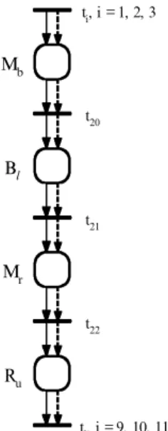
requesting a crane to unload parts to a storage bay.A storage command sequence consists of a sequence of four action macros. The ® rst action macro is a movement macro that moves a crane device from its current location to a bu er station. The second action macro is a loading macro that per-forms part loading at the bu er. The third action macro is a movement macro that moves a crane device from the bu er to a rack. The last action macro is an unloading macro that performs part unloading at the rack.
The storage command sequence module is illustrated in ® gure 5. Note that an input transition of a storage operation macro place, ti (i=1, 2 or 3
)
, in CPL is aninput transition of a storage command sequence module in CCL. Similarly, an output transition of a storage operation macro place, tj ( j=9, 10 or 11
)
, in CPLis an output transition of a storage command sequence module in CCL. Here, macro places, Mb and Mr, are used to stand for point-to-point (PTP
)
movement executionmacros. The subscripts, b and r, are used to indicate the movement from the current location to a bu er station and from a bu er station to a rack, respectively. Macro place Bz represents a bu er loading/unloading execution macro. The subscriptz is
used to signal that the loading action is requested. Macro place Rustands for a rack
loading/unloading execution macro. The subscript u is to signal that an unloading
ti, i = 1, 2, 3 tj, j = 9, 10, 11 t20 t21 t22 Mb Mr Bl Ru
Figure 5. The storage command sequence module. (Note: tiand tjare the input and output
action is requested. The physical meaning of each storage command element in CCL is presented in table 2.
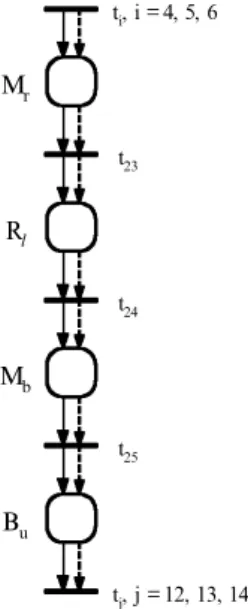
3.4.2. Retrieval command sequence module
The retrieval command sequence module is similar to the storage command sequence module. Whenever a retrieval command token and crane device token enter a macro place ( Ro, Rr, or Rb
)
in CPL, the retrieval command sequenceimmedi-ately takes place in CCL. A retrieval command sequence module may possess the following four major functions:
(1
)
requesting a crane to move from current location to a designated storage bay location in rack;(2
)
requesting a crane to load parts from the storage bay;(3
)
requesting a crane to move from the rack to the I/O bu er; or (4)
requesting a crane to unload parts to the bu er.A retrieval command sequence consists of a sequence of four action macros. The ® rst action macro is a movement macro that moves a crane device from its current location to a designated storage bay location in the rack. The second action macro is a loading macro that performs part loading at the rack. The third action macro is a movement macro that moves the crane device from the rack to the bu er. The last action macro is an unloading macro that performs part unloading at the bu er.
The retrieval command sequence module is illustrated in ® gure 6. Note that an input transition of a retrieval operation macro place, ti(4, 5 or 6
)
, in CPL is an inputtransition of a retrieval command sequence module in CCL. Similarly, an output transition of a retrieval operation macro place, tj ( j=12, 13 or 14
)
, in CPL is anoutput transition of a retrieval command sequence module in CCL. Here macro places, Mb, Mr, Rz and Bu, are the same macro planes as those used in the storage
command sequence module. The physical meaning of each retrieval command ele-ment in CCL is described in table 2.
3.4.3. Homing command sequence module
When a homing command token and crane device token enter a macro place, H, in CPL, the homing command sequence immediately takes place in CCL. A homing command sequence module may possess one of the following two functions:
(1
)
requesting a crane to move from its current bu er station back to its home location; or(2
)
requesting a crane to move from its current rack location back to its home position.Point-to-point movement Mb to move a crane from its current location to a bu er
execution macro station
Mr to move a crane from its current location to a rack
Mo to move a crane from its current location to home
Bu er loading/unloading Bz to load parts to a ctrane at a bu er station execution macro Bu to unload parts from a crane to a bu er station
Rack loading/unloading Rz to load parts to a crane at a rack execution macro R u to unload parts to a crane at a rack
A homing command sequence consists of a single action macro. The action macro is a movement macro that moves a crane device from its current bu er/ rack location to its home location. A homing command sequence module is given in ® gure 7. Note, a simple movement action from the current position to home position can satisfy the requirements of a homing command sequence module. Therefore, a homing command sequence module includes only one movement macro place, Mo. Transitions tk (k=17 or 18
)
and t19 are the input and outputtransitions of the module. The physical meaning of the homing command element is also presented in table 2.
3.4.4. Token movement rules of the CCL
The main function of the CCL is to decompose a requested job into a logic operation sequence. To allow a job to be executed by a crane device in CCL, a crane device token and command operation token must appear in the same place at the same time in CCL to enable a macro operation.
3.4.5. Structural properties of the CCL
All three operation modules in CCL have the same functional structure. For simplicity, the homing command sequence module is selected for illustration. The incidence matrix of the homing command module is given as
ti, i = 4, 5, 6 tj, j = 12, 13, 14 t23 t24 t25 Mr Mb Rl Bu
Figure 6. The retrieval command sequence module. (Note: tiand tjare the input and output
transitions of the module, respectively.)
Mo
t19
tk, k = 17, 18
Figure 7. The homing command sequence module. (Note: tiand tjare the input and output
Mo
Ahom e= tk
t19
2
-
2 .Since all three modules have the same structure, their structural properties should also be the same. Based upon the above incident matrix of the homing command, one can easily reach the following conclusions for structural properties.
(1
)
L iveness: each module contains a source and sink transition. The CCL mod-ules are structurally live.(2
)
Controllability: since the CCL modules are not MGs, the completely control-lable property cannot be identi® ed.(3
)
Conservativeness: there does not exist a 1´
1 non-negative y vector, y=/0 such that ACCLy=0. Hence, the CCL modules are not conservative.(4
)
Repetitiveness: there exists a 2´
1 vector x=[
1 1]
. Since x is of positive integers and ACCLT x³
0, the CCL modules are structurally repetitive.(5
)
Consistency: there exists a 2´
1 vector x=[
1 1]
. Since x is of positive inte-gers and ACCLT x³
0, the CCL modules are structurally consistent.3.5. Command execution layer
Three types of tasks are required in CEL. These include: (1
)
the movement of a crane device from its current location to a `speci® c location’; (2)
the loading of parts onto the crane; and (3)
the unloading of parts from the crane. Therefore, three corresponding operation modules are developed for the CEL. These operation mod-ules include the point-to-point (PTP)
movement execution module, he rack loading/ unloading execution module, and the bu er loading/unloading execution module. These modules are responsible for the tasks of crane movement, part loading/ unloading at a rack and part loading/unloading at a bu er station, respectively. 3.5.1. PTP movement execution moduleAlthough there are eight types of movements in CPL, a PTP movement execution module can be used to describe all eight types of movements. A PTP movement execution module contains both the x-coordinate and y-coordinate ordinary places. These places are used to address the physical locations of bays in racks, the locations of bu er stations and the location of home. For instance, a unit operation module with a size of six
´
three is assumed having its home position located at a bu er station of (x,
y) = (0,
0). The addresses of three bays on three levels of the ® rst column are (x,
y) = (1,
1), (1,
2) and (1,
3), respectively. Any location that a crane is allowed to move to is given an address in the model.Besides the two (i.e. x-coordinate and y-coordinate
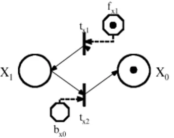
)
serial address places, some command operation signals are usually required to instruct a crane to move. A forward and backward series of signal places is constructed along each x- and y-coordinate address places. Figure 8 shows the basic unit of a PTP movement execu-tion module. The module consists of two ordinary places and two command places. The ordinary places, X0 and X1, represent the two aligned positions in the samedirection. The signal places, fx1 and bx0, represent forward and backward moving
signal places. If a signal token is deposited to the signal place, fx1 and a crane device
token is in place X0., the transition tx1is ® red and the crane is moved forward. If a
X1, the transition tx2 is ® red, and the crane is moved backward. After the transition,
tx1or tx2, is ® red, the crane token is deposited to the output place of the transition
and then the signal token is removed.
When a crane device token and command token enter a movement macro place in CCL, the macro place is zoomed in and these tokens are moved immediately into the PTP movement execution module. In the module, a pair of crane device tokens is deposited into its current address. To generate the `from-to’ guide path, the com-mand token is split into two (x-signal and y-signal
)
series of forward or backward signal tokens and are deposited into the associated signal places.A PTP movement execution module for a unit operation module of m by n is composed of m basic units in the x-direction and n basic units in the y-direction. Figure 9 shows a PTP movement execution module of 4 columns (m=4
)
by 3 rows (n=3)
. The home of the module is located at a bu er station of (X,
Y) = (0,
0). The X serial nets represent the x-direction movement execution nets and the Y serial nets represent the y-direction movement execution nets. Note that the transitions tinandttoutare connected to the ® rst and last places of the module. In the module, there is a
pair of the ® rst places, Xiand Yj, i is an integer, which represents the current location
of the crane and a pair of the last places, Xkand Yz ,z is an integer, representing the
destination of the movement task.
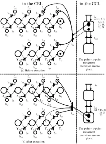
3.5.2. Token movement rules in PTP movement module.
The token movement rules in this module can be illustrated by using the follow-ing example. If the current crane location is at (X
,
Y) = (0,
0) and the crane is instructed to move to the second column in the ® rst row of the rack, the from± to path is (0, 0)
to (2, 1)
. A pair of crane device tokens will be deposited into places X0and Y0. Both x and y signal serial tokens will be deposited into forward signal places
fx1and fx2, for x serial and place fy1 for y serial and the input transition, tin, of this
module is directed to these ordinary and signal places, respectively. The result is given in ® gure 9(a
)
. When the crane arrives at (X,
Y) = (2,
1), the pair of crane device tokens is at places X2 and Y1 and all the signal tokens are removed. At thismoment, the crane arrives at the `to’ position. The output transition, tout, of this
module receives these directed arcs from the pair of the ordinary places representing the `to’ position and signal places fx1, fx2 and fy1. Thus, the command and crane
device tokens are retrieved through the transition tout. The result is given in ® gure 9(b
)
.3.5.3. Structural properties of the PTP movement module
The PN of this module is varying with the size (i.e. the numbers of rows and columns
)
of the AS/RS. In this module, the pair of output places of transition tinandthe pair of input places of transition tout are determined by the from± to path. fx1
tx1
tx2 bx0
X1 X0
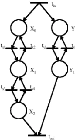
However, the basic structure of the module is the same. When a PTP movement execution macro place in CCL is zoomed in, all the necessary signal tokens occur in the signal places at once. Once a series of transitions is ® red one by one, the crane token proceeds to the next ordinary place step by step and the signal token is deleted one by one. The signal place is an auxiliary place in CEL. Therefore, we remove signal places from the model when the structural properties are analysed. Since the from± to path is from (0, 0
)
to (2, 1)
, the output places of tin include place X0 andplace Y0and the input places of toutinclude place X2and place Y1The PN structure
is structured and presented in ® gure 10. The incident matrix of the execution module is given as X0 X1 X2 Y0 Y1 APOP= tin tx1 tx2 tx3 tx4 ty1 ty2 tout 1 0 0 1 0
-
1 1 0 0 0 1-
1 0 0 0 0-
1 1 0 0 0 1-
1 0 0 0 0 0-
1 1 0 0 0 1-
1 0 0-
1 0-
1 fx1 fx2 fx3 fx4 bx0 bx1 bx3 bx2 fy1 fy2 fy3 by0 by1 by3 X0 X1 X2 X3 X4 Y0 Y1 Y2 Y3 The point-to-point movement execution macro place fx1 fx2 fx3 fx4 bx0 bx1 bx3 bx2 fy1 fy2 fy3 by0 by1 by3 X0 X1 X2 X3 X4 Y0 Y1 Y2 Y3 The point-to-point movement execution macro placein the CEL in the CCL
(a) Before execution
(b) After execution tx1 tx3 tx5 tx7 tx8 tx6 tx4 tx2 ty1 ty3 ty5 ty2 ty4 ty6 tx1 tx3 tx5 tx7 tx8 tx6 tx4 tx2 ty1 ty3 ty5 ty6 ty4 ty2 tin in = 1, 2, 3, 4, 5, 6, 17, 18, 21, 24 tin tout tout tin tout out = 19, 20, 22, 23 25
Based upon the incident matrix given above, one may summarize the structural properties of the PTP movement module as follows.
(1
)
L iveness: each module contains a source and sink transition. The CCL mod-ules are structurally live.(2
)
Controllability: since the module is not a MG, the completely controllable property cannot be identi® ed.(3
)
Conservativeness: there does not exist a 5´
1 non-negative y vector and y=/0 such that APOPy=0. Therefore, the CCL modules are not conservative.(4
)
Repetitiveness: there exists an 8´
1 vector x=[
1 2 1 2 1 2 1 1]
. Since x is of positive integers and APOPT x³
0, these modules are structurally repetitive.(5
)
Consistency: there exists an 8´
1 vector x=[
1 2 1 2 1 2 1 1]
. Since x is of positive integers and ATPOPx=0, the CCL modules are structurally consistent.3.5.4. Rack loading/unloading execution module
A rack loading/unloading module is also composed of the device operation and command operation. The device operation is used to instruct the crane device to perform loading/unloading tasks and the command operation is to provide the crane with two kinds of information (i.e. position con® rmation and loading/unloading signal
)
. A crane device token appearing in an ordinary place of the module repre-sents the status of the physical crane. Two types of signal places, i.e. the position con® rmation place and loading/unloading signal place, are used in the module. A signal token in a position con® rmation signal place con® rms the position that a part is to be deposited to or to be withdrawn from. For instance, when the crane arrives at a position, a token in the signal place, called `Left’, will direct the crane to serve the rack on the left-hand side. A token in the loading or unloading signal place will direct the crane for loading or unloading operations. The detail picture of a rack loading/unloading execution module is given in ® gure 11. All elements of a rack module are detailed in table 3.3.5.5. Bu er loading/unloading execution module
The bu er loading/unloading execution module is similar to the rack loading/ unloading execution module. The operations in the module can be classi® ed into two categories, i.e. the device operation and command operation. They have the same
tin Y0 X0 tx1 tx2 ty1 ty2 X1 Y1 tx3 tx4 X2 tout
physical meanings as those in the rack loading/unloading module. A signal token in the signal place indicates the crane is at the right position ready for bu er service. A token in the loading/unloading signal place can instruct the crane to perform loading/ unloading operations. Usually there exists only one I/O bu er station in each unit operation module. For some speci® c cases, it is possible to have more than one bu er station in each unit operation module. Figure 12 shows the bu er loading/unloading execution macro for one I/O station. Table 4 lists all elements of the module.
3.5.6. Token movement rules in rack (bu er
)
loading/unloading execution module The rules for token development in both the rack and bu er loading/unloading execution modules have the following distinguished features.(1
)
When a command token enters a rack (or bu er)
loading/unloading execu-tion macro place from the CCL, a command token is split into the posiexecu-tion con® rmation token and loading/unloading token.t30 t31 t32 t33 t34 t35 t36 t38 t39 t37 Rleft
Uleft Lleft Uright Lleft
Rright
Rout
Left Right
Unload LoadUnload Load
Rin
ti, i = 22, 23,
tj, j = 9, 10, 11, 24
Figure 11. The rack loading/unloading execution module.
Rin a crane is located at the rack
Rleft a crane is ready to serve the track on the left-hand side
Rright a crane is ready to serve the rack on the right-hand side
Ordinary places Uleft a crane is to unload the part to the left-hand side of the rack
Lleft a crane is to load the part from the left-hand side of the rack
Uright a crane is to unload the part to the right-hand side of the rack
Lright a crane is to load the part from the right-hand side of the rack
{
Rout a crane completes a loading/unloading task at the rackLeft to instruct a crane to serve the rack on the left-hand side Command places
{
LoadRight to instruct a crane to serve the rack on the right-hand sideto instruct a crane to perform a loading taskUnload to instruct the crane to perform an unloading task Table 3. Elements of the rack loading/unloading execution module.
(2
)
Each signal or ordinary place is restricted to have a single token. There is at most one device token appearing in the module since physically there is only one crane in existence.(3
)
Whenever a transition is ® red, the signal token is removed from the net and the crane device token is moved to the next ordinary place.(4
)
Once a movement is executed, all of the signal tokens are removed. The original command token appears again and returns to the CCL along with the crane token.3.5.7. Structural properties of the rack (bu er
)
loading/unloading execution module The structures of the rack and bu er loading/unloading execution modules are similar. The rack module is the combination of two bu er modules. According to Murata’s reduction rules (1989)
, the structures of the rack and bu er loading/ unloading execution modules are the same. For simplicity, the bu er execution module is selected for illustration. Here, we remove signal places from the model when the structural properties are analysed. The incident matrix of the bu er execu-tion module is given ast41 t42 t43 t44 Bin U L Bout Unload Load ti, i = 20, 25 t40 Pok tj, j = 12, 13, 14, 21 R
Figure 12. The bu er loading/unloading execution module.
Bin a crane is located at a bu er
Ordinary places
{
UR a crane is in the right position and ready to execute a taska crane is to unload the part to a bu er station L a crane is to load the part from a bu er stationBout a crane completes a loading/unloading task at a bu er
Command places Pok to con® rm that a crane is in the right position
Load to instruct the crane to perform a loading task
{
Unload to instruct a crane to perform an unloading task Table 4. Elements of the bu er loading/unloading execution module.Bin R U L Bout AB = ti t40 t41 t42 t43 t44 tj 1 0 0 0 0
-
1 1 0 0 0 0-
1 1 0 0 0-
1 0 1 0 0 0-
1 0 1 0 0 0-
1 1 0 0 0 0-
1Based upon the incident matrix given above, the structural properties of the bu er and rack loading/unloading execution modules can be easily observed and summarized as follows.
(1
)
L iveness: each module contains a source and sink transition. The two mod-ules are structurally live.(2
)
Controllability: Since the two modules are not MGs, the completely control-lable property cannot be identi® ed.(3
)
Conservativeness: there does not exist a 5´
1 non-negative vector y, and y=/0 such that Ay=0. The two modules in CEL are not conservative. (4)
Repetitiveness: there exists a 7´
1 vector x=[
2 2 1 1 1 1 2]
. Since x is ofposi-tive integers and ATBx
³
0, the bu er module is structurally repetitive. Therack module can be identi® ed to be structurally repetitive by the same reason. (5
)
Consistency: there exists a 7´
1 vector x=[
2 2 1 1 1 1 2]
. Since x is of positive integers and ATBx=0, the module is structurally consistent. The rack modulecan be identi® ed to be structurally consistent by the same reason.
The results of the above structural property analysis indicate that the proposed hierarchical four-layer AS/RS model structure is robust. The analysis results are summarized in table 5.
4. Conclusions
This paper presents a PN based hierarchical structure for AS/RS operation modelling. The proposed structure has several distinct features including: (1
)
theLayer/module CPL CEL
Property CTL Crane CL Crane+CL CCL PTP Bu er/Rack
Conservative
-
+-
+-
-
-Repetitive + + + + + + +
Consistent + + + + + + +
Controllable + < < < < < <
Structurally live + + + + + + +
Note: `CL’ represents control loop; `PTP’ represents the point-to-point movement execution module; `Bu er/Rack’ represents the bu er and rack loacing/unloading execution modules.
Table 5. Structural properties of the four-layer AS/RS model, where+,
-
and< in each row indicate holding, not holding, or undecided the structural properties in the row for each net indicated in the column.approach is general, since the proposed unit operation module structure is common to every unit-load AS/RS; (2
)
the method is e ective since the function of informa-tion ¯ ow is distinguished from the operainforma-tion of the crane; (3)
the implementation is systematic since a hierarchical four-level structure is adopted as the general AS/RS operation mode; (4)
the system model is robust since the robustness of the system is insured layer by layer; (5)
the system management policies can be incorporated and coordinated by employing the modular concept in the process of modelling; and (6)
various basic operation modules of an AS/RS can be established ® rst and then assembled to construct complicated AS/RS models.
Subsequent work on the analysis and evaluation of the performance of an AS/RS will be e ectively done by extending the PN model to the coloured-timed PN model. For an AS/RS, the state of the system varies from time to time. Therefore, the PN structure should be equipped with temporal capabilities for modelling the dynamic aspects of AS/RSs. The use of asynchronous system models for modelling temporal behaviour requires that they be augmented by introducing a time parameter. This parameter provides a common frame for the expression of the speeds of their com-ponents. Also, since tokens are divided into two general categories (availability of shared resources and actions
)
, di erent colours are used to distinguish di erent tokens.References
Archetti, F., Sciomachen, A. and Gaivoronski, A. 1991, Optimal control policies for automated storage/retrieval system using PN models and stochastic optimization. In
Proceedings of the Fourth International Workshop on Petri Nets and Performance Models, J. Billington, et al. (eds)(IEEE Computer Society, Melbourne, Australia)2± 5 December, pp. 258± 267.
Bozer Y. A. and White, J. A.1984, Travel-time models for automated storage/retrieval systems. IIE Transactions,6, 329± 338.
Chang, D. T., Wen, U. P. andLin, J. T.1995, The impact of acceleration/deceleration on travel-time models for automated storage/retrieval systems. IIE Transactions, 27, 108±
111.
Chincholkar, A. K., Chetty, O. V. K.andKuppuswamy, G.1994, Analyses of an auto-mated storage and retrieval system using stochastic coloured Petri nets. Advances in
Modelling & Analysis C:System Analyses, Control & Design,44, 19± 30.
Chincholkar, A. K. and Chetty, O. V. K. 1996, Simultaneous optimisation of control factors in automated storage and retrieval systems and FMS using stochastic coloured Petri nets and the Taguchi method. International Journal of Advanced Manufacturing
Technology,12, 137± 144.
D’Souz a, K. A.andKhator, S. K.1994, A Petri net approach for modelling controls of a computer-integrated assembly cell. International Journal of Computer Integrated
Manufacturing,6, 302± 310.
Egbelu, P. J.1991, Framework for dynamic positioning of storage/retrieval machines in automated storage/retrieval system. International Journal of Production Research, 29,
17± 37.
Hwang, H.andLee, S. B.1990. Travel-time models considering the operating characteristics of the storage and retrieval machine. International Journal of Production Research,28,
1779± 1789.
Jafari, M. A.1992, An architecture for a shop-¯ oor controller using coloured Petri nets.
International Journal of Flexible Manufacturing Systems,4, 159± 181.
Jensen, K.1996, Coloured Petri Nets: Basic Concepts, Analysis Methods and Practical Use (Berlin: Springer).
Kaz uo W., Kenji, Y., Masako, N.andYasuyoshi, K.1993, Simulation system for material ¯ ow in FA line based on extended Petri nets. Research and Development, 43, 54± 57.
Knapp, G. M. and Wang, H.-P. 1992, Modeling of automated storage/retrieval systems using Petri nets. Journal of Manufacturing Systems,11, 20± 29.
Lin, S.-C.andWang, H.-P.1995, Modeling an automated storage and retrieval system using Petri nets. International Journal of Production Research, 33, 237± 260.
Moore, K. E.andGupta, S. M.1995, Stochastic coloured Petri net models of ¯ exible manu-facturing systems: material handling systems and machining. Computers Ind. Engng,29,
333± 337.
Moore, K. E. and Gupta, S. M.1996, Petri net models of ¯ exible and automated manu-facturing systems: a survey. International Journal of Production Research, 34, 3001±
3035.
Murata, T.1989, Petri nets: properties, analysis and applications. Proceedings of the IEEE,
77, 541± 580.
Peterson , J. L. 1981, Petri Net Theory and the Modelling of Systems (Englewood Cli s: Prentice-Hall. NJ).
Ramaswamy, S.andValavanis, K. P.1994, Modeling, analysis and simulation of failures in a materials handling system with extended Petri nets. IEEE Transactions on Systems,
Man and Cybernetics,24, 1358± 1373.
Randhawa, S. U. andShroff, R.1995, Simulation-based design evaluation of unit load automated storage/retrieval systems. Computer Ind. Engng, 28, 71± 79.
Sun, T.-H., Cheng, C.-W.andFu, L.-C.1994, A Petri net based approach to modeling and scheduling for an FMS and a case study. IEEE Transactions on Industrial Electronics,
41, 593± 601.
Zhou, M.1996, Petri net modelling of bu ers in automated manufacturing systems. IEEE
Transactions on Systems, Man and Cybernetics, part B: Cybernetics,26, 157± 164.
Zhou, M., McDermott, K. and Patel, P. A.1993, Petri net synthesis and analysis of a ¯ exible manufacturing system cell. IEEE Transaction on Systems, Man and Cybernetics,