Model based Sub-Resolution Assist Features
Using an Inverse Lithography Method
Jue-Chin Yu, and Peichen Yu
*De
partment of Photonics and Institute of Electro-Optical Engineering,
National Chiao-Tung University, Hsinchu, Taiwan, R.O.C.
Hsueh-Yung Chao
Department of Communication Engineering,
National Chiao-Tung University, Hsinchu, Taiwan, R.O.C.
*Electronic mail: yup@faculty.nctu.edu.tw
ABSTRACT
The conventional segment-based OPC approach has been applied successfully for many CMOS generations and is currently favored. However, Inverse lithography technology (ILT) is a promising candidate for next-generation optical proximity correction (OPC). Still, there are issues that need to be thoroughly addressed and further optimized. In this work, we propose a model-based pre-OPC flow where the sizing of drawn patterns and placement of surrounding sub-resolution assist features (SRAF) are simultaneously generated in a single iteration using an ILT method. The complex patterns can then be simplified for a conventional OPC solution.
Keywords: optical proximity correction, inverse lithography, sub-resolution assist features
1. Introduction
As CMOS manufacturing processes push towards the 22nm node, many resolution enhancement techniques (RET) have been proposed and sometimes applied with varying degrees of success. These include immersion lithography, alternating phase shift masks, double patterning and various inverse lithography methods. The selection among available RET options depends on a careful balance between manufacturing costs and pattern fidelity. Since the conventional segment-based OPC approach has been applied successfully for many CMOS generations, it is still favored by the industry. As a result, sub-resolution assist features (SRAF) remain a most efficient solution to improve pattern fidelity and enhance image resolution due to minimal technology-transition risks and costs. However, the current methodologies of SRAF placement can be rather primitiveand extremely pattern-dependent. In general, SRAFs are limited to simple geometries whose placement is determined by rules. In the currently available model-based methods there are three major problems with SRAF generation: (1) SRAF placements are substantially rule-based, and the rules are followed by using simple regular patterns, for example bars and spaces. Such rules may not be accurate enough for complicated geometries in a commercial design; (2) The correction process and SRAF arrangement are completed in two separate steps. (3) Only the main pattern is consider in correction process; SRAFs are not further optimized during the correction phase.
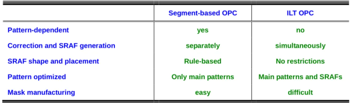
Table 1.Comparisons between segment-based OPC and ILT OPC.
Segment-based OPC ILT OPC
Pattern-dependent yes no
Correction and SRAF generation separately simultaneously
SRAF shape and placement Rule-based No restrictions
Pattern optimized Only main patterns Main patterns and SRAFs
Mask manufacturing easy difficult
Recently, inverse lithography technology (ILT) has become a promising candidate for next-generation optical proximity correction (OPC) due to the absence of pattern-dependent heuristics. However, there are still many known issues that need to be thoroughly addressed and further optimized, including run time, tile stitching problems in full-chip applications, and mask manufacturability / inspection, among others. Also, the cost functions used, while providing multiple degrees of freedom for optimizing the edge-placement error (EPE), mask error enhancement factor (MEEF) and aerial image contrast, are not straightforward and may be pattern-dependent. In general, convergence and pattern fidelity using ILT require further study. The segment-based OPC and ILT-OPC methods show complementary advantages and disadvantages to each other. Table 1 summarizes the strengths and weaknesses for segment-based OPC and ILT OPC.
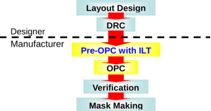
To maintain a segment-based OPC while achieving some of the optimized corrections produced by ILT, we propose a model-based pre-OPC flow where the sizing of drawn patterns and placement of surrounding sub-resolution assist features (SRAF) are simultaneously generated in a single iteration using an inverse lithography method. The complex patterns can then be simplified to serve as the input to a conventional OPC solution. Figure 1 illustrates the modified design/manufacturing flow with the insertion of ILT-modified drawn patterns with SRAFs in pre-OPC. The inverse lithography method proposed in this study features a specialized “pixel-flipping” approach at a particular pixel resolution. To bias the correction towards an optically desirable pattern, innovative wavefront expansion and damping techniques are employed. Furthermore, a look-up table and suitable cashing are adopted to speed up the computation. The simplification of mask patterns is achieved based on image central moments. Finally, the simplified masks can be snapped to manufacturable 45-degree and axis-aligned line segments if required by design rules.
Fig. 1. The modified design/manufacturing flow with the insertion of model-based SRAFs using ILT.
2. Methodology
Since the introduction of the inverse problem formulation for optical microlithography by Sayegh, Nashold and Saleh [1-2], many pixel-based inversion algorithms have been demonstrated, taking into account coherent, incoherent, and partially coherent optical systems. The inverse problems have been solved by linear programming, quadratic programming, or nonlinear formulations based on the assumptions made for the optical systems [3-8]. The traditional pixel-flipping techniques are replaced with elaborated algorithms such as local variations and gradient descent methods, which have also been demonstrated on large-scale layouts [4, 9-11]. Although pixel-flipping techniques could also be very efficient for inverse lithography, the techniques exhibit some known issues. First, solutions could be easily stuck in local minima. Second, the resulting masks are randomly pixelated, and require refinement or post-processing for manufacturability.
In this study, we develop an innovative pixel-flipping algorithm where the pixel-flipping is biased by a Wavefront Expansion technique. We further incorporate a wavefront-based damping scheme and demonstrate that the resulting masks are similar to those obtained by more elaborated algorithms. For application as a pre-OPC flow, a single iteration is often sufficient for SRAF generation and to determine the bias of main features.
Layout Design DRC
OPC Verification Mask Making
Pre-OPC with ILT Designer
20 40 0 00 80 IOU 120 Original Mask 20 40 80 80 lOU 120 PUSin in (a)
Wavefnnnl Znne Templele
20 40 80 80 lOU 120
(8)
Original Mask
20 40 80 80 lOU 120
pnnigins
Waveftont Zone Templele
20 40 80 80 IOU 120 s-position (4) Original Mask 20 40 80 80 lOU 120 pnnigins
Waveftont Zone Templele
20 40 80 80 IOU 120 s-position (I) 20 40 00 80 IOU 120 Original Mask 20 40 80 80 lOU 120 PUSin in (8)
Wavefnnnl Znne Templele
20 40 80 80 lOU 120
(k)
In our simulations, we use a conventional illumination source at 193 nm wavelength with a numerical aperture of NA=0.7 and a coherence factor of σ=0.7. The lithographic models are developed based on Köhler illumination method, following Hopkin’s imaging equation [12-13] and the singular value decomposition (SVD) of the transmission cross coefficients (TCCs) for the eigenfunction expansion of the aerial image [13-14]. The kernels are then converted to a look-up table format for fast convolution. Moreover, the convolution values of each kernel are cached for individual pixels to speed up the computation.
2.1 Wavefront Expansion technique
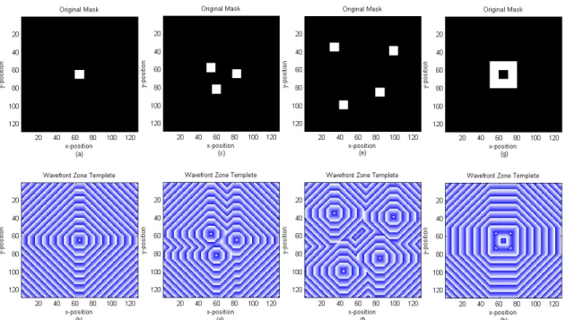
At the core of our ILT approach is a biasing technique based on a Wavefront Expansion. For any particular layout, we construct a wavefront from the feature’s edges both inwards and outwards. This way, we can construct a complete wavefront from a small region (or even a single point) inside each feature all the way to the edge of the image. Each wavefront, starting from the innermost, receives an index, and all the pixels on the layout are processed in order according to this index. A few examples of wavefront template are shown in Fig. 2. It is worth noting that this biasing technique will clearly identify pixels that are equidistant from two or more features.
Fig. 2. Wavefront templates for various masks: (a) an isolated via with a dimension of 100nm x 100nm and (b) the corresponding wavefront template; (c) three semi-nested vias of the same dimensions and (d) the corresponding wavefront template; (e) four semi-isolated vias and (f) the corresponding wavefront template; (g) a square donut with a width of 200nm and an opening with an area of 100nm x 100nm and (h) the corresponding wavefront template. For illustration purposes we repeat colors from dark blue to white but the corresponding indices increase strictly monotonically.
Once we have constructed the complete wavefront indices for a particular layout, denoted as the wavefront template, we proceed to evaluate pixels according to this order, from innermost to outermost. A key procedure in our ILT approach is that all the pixels in any particular index are evaluated before any change is propagated to the mask. In other words, for each “ring”, we evaluate if flipping a particular pixel is beneficial according to the cost function, but we do not immediately propagate this change. Only when all the pixels in a given index have been evaluated are they all updated at the same time and considered in the cost function for the next wavefront index. This will bias the final mask towards configurations that are center symmetric to the drawn patterns.
To compensate for the increasing size of the wavefronts as they move towards the edge of the layout, we introduce the concept of wavefront-based damping, as described in the next section. In a nutshell, this technique assigns a decaying weight to wavefronts that are large but should not have a large influence on the final target image for being far away from the features.
2.2 Cost functions and wavefront-based damping
Inverse lithography is an optimization problem [15-16] that tries to find the mask which generates an aerial image that deviates the least from a given target. The process of solving the problem involves three distinct parts: (1) the determination of a target image or contour, (2) a cost function that evaluates how far a given mask is from generating the desired target, and (3) an algorithm to search for candidate masks. The last part was described in the previous section. Here we address the first two.
The target aerial images are constructed from drawn features, where sharp corners and edges are smoothed to facilitate the convergence of the optimization problem. Moreover, the image intensity along the edges of drawn features is set to the constant threshold at which we desire contours to print. We define a cost function consisting of two parts. As seen in eq. (1), the first part measures the intensity differences between the target aerial image and the one generated by a given mask. The second part, shown in eq. (2), measures the accumulated edge placement errors. Both parts are assigned proper weights to achieve a balance between adequate image contrast and desired contours. The optimization algorithm is then driven to minimize the cost function as the total summation, as shown in eq. (3). To summarize, our cost function has the following form:
∑∑
= =Ψ
Ω
−
Φ
Ω
=
m i n j j i j i image imagew
f
x
y
x
y
F
1 1)
,
,
(
)
),
,
(
(
(1))
,
(
,
)
,
(
)
),
(
(
1 k k k l k k k contour contourw
f
z
z
z
x
y
F
=
∑
Ψ
Ω
−
Φ
Ω
=
= (2).
min
→
+
contour imageF
F
(3):
F
image and contour cost contributions,:
Ψ
mask function,:
)
,
(
Ψ
Ω
f
aerial image of a mask function with a wavefront damping coefficient,:
Ω
wavefront damping coefficient,:
Φ
target aerial image or contour,:
w
weights of the corresponding cost functions,where m and n are layout dimensions in x and y directions, and l is the number of pixels which correspond to the target contour.
Moreover, it is worth noting that we introduce a wavefront damping coefficient in the cost function. The coefficient is determined based on the wavefront indices of individual pixels. We will show later that this technique effectively eliminates undesired patterns generated at remote distances from the drawn features. This is an important result, as it minimizes the SRAF conflicts occurring on template boundaries.
2.4 Mask simplification
There can be several ways to simplify the ILT-generated mask patterns into regular polygons (rectangles). We choose a technique based on central moments [17]. The algorithm is as follows:
1. Extract all the connected components (clusters) from the input image. 2. Filter out small, negligible clusters by size.
3. Approximate the orientation and size of these clusters using central moments. 4. Snap resulting rectangles to manufacturable 45-degree and axis-aligned line segments.
In order to extract all the connected components from the pixelated ILT image, we use a binary segmentation technique. The technique is a one-pass, line-sweep algorithm that “builds” clusters one row at a time. The end result is a collection of separate regions whose union is equal to the original image. After this procedure is complete, we filter out small clusters that can be safely ignored due to their small size and consequently small influence.
Next, we consider each cluster individually and extract shape information using the statistical property of central moments. Each cluster can be considered to be a probability distribution, and as such, we compute the cluster’s moments as:
(
) (
) ( )
∑∑
−
−
=
x y q p pqx
x
y
y
I
x
,
y
µ
,
(4)
where x and y are pixel coordinates and I is the image function for one particular cluster. The central moments are thus defined as: 2 00 20 00 20 20
'
x
M
M
−
=
=
µ
µ
µ
.(5)
2 00 02 00 02 02'
=
µ
µ
=
M
M
−
y
µ
.(6)
x
y
M
M
−
=
=
00 11 00 11 11'
µ
µ
µ
.(7)
With these, we can construct the covariance matrix for each cluster:
[
]
⎥
⎦
⎤
⎢
⎣
⎡
=
02 11 11 20'
'
'
'
)
,
(
cov
µ
µ
µ
µ
y
x
I
.(8)
It is well-known that the eigenvectors of this matrix correspond to the major and minor axes of the probability distribution, or in our case, a single cluster. It is also known that the eigenvalues are proportional to the square of the main dispersion (cluster axes). We know the cluster size (pixel count) and therefore can scale the eigenvalues while maintaining their relative magnitudes.
With the eigenvectors and scaled eigenvalues we can create a rectangle for each cluster that has the same area and is aligned in the same way according to the dominant dispersion. Furthermore, we can snap each line segment to be either axis-aligned or at 45-degrees for mask manufacturability. An example of this procedure is shown in Fig. 5.
0_s ISIC uld D'*S 1St Eli. MS —. lit Cmtaa us D*S 1St Elp
I:(( • .) I:
20 40 80 80 100 120 20 40 80 80 100 120
s-position s-position
1St uS D*S 1St Eli. MS —. lit Cutaj uS D*S 1St Eli.
20 40 80 80 100 120 s-position 20 40 80 80 IOU 80 40 80 80 lOU 120 ponilion
3. Results and Discussion
In this section, we compare the optimized masks generated with and without the incorporation of the wavefront based damping. The examples presented include an isolated via with a dimension of 100nm x 100nm, two separated vias of the same dimensions, three semi-nested vias of the same dimensions, and finally a square donut with a width of 200nm and an opening with an area of 100nm x 100nm. The results are all computed in a single iteration with our algorithm. Lastly, the simplification of ILT-generated mask is demonstrated using an example of four vias.
3.1 Mask optimization without wavefront-based damping
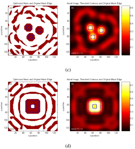
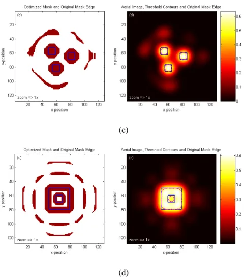
As seen in Fig. 3(a) to 3(d), the corrected masks and the drawn patterns are shown on the left-hand-side, while the calculated aerial images and contours are shown on the right-hand side. First, we note that the main features are now surrounded by SRAFs along rings. For isolated features, as seen in Fig. 3(a) and 3(d), the arrangement of mask patterns resembles octagons in shape, clearly determined by the Wavefront Expansion. The sizes of bright and dark SRAFs are determined by the model and hence could be big or small in shape regardless of position. The EPEs of different masks are satisfying to some extent, except that the center of the square donut in Fig. 3(d) does not print. However, the aerial image contrast is limited due to the spreading distributions of SRAFs. These observations are not surprising, since the entire layout is one of many potential candidate masks for an inverse lithography problem. Furthermore, it is commonplace that an optimization algorithm converges to a local minimum that may not best represent the desired solution. The wavefront-based damping introduced next allows the algorithm to quickly arrive near the vicinity of good ILT solutions, similar to results obtained by other, more elaborated algorithms.
(a)
OPIEItS 1St uld D*S 1St Eli. MS —. lit Cutaj us D*S 1St Eli. 80 80 20 40 80 80 100 120 s-position s-position 20 40 80 80 IOU 20 40 80 80 lOU 120
1St uS D*S 1St Eli. MS —. lit Cutaj uS D*S 1St Eli.
20 40 80 80 100 120 s-position 20 40 80 80 IOU 80 40 80 80 lOU 120 ponilion
(c)
(d)
Fig. 3. The optimized masks and corresponding aerial images are computed without wavefront-damping treatments. The drawn patterns are plotted in blue solid lines and printed contours in pink dashed lines. The examples presented include (a) an isolated via with a dimension of 100nm x 100nm, (b) two separated vias of the same dimensions, (c) three semi-nested vias of the same dimensions, and finally (d) a square donut with a width of 200nm and an opening with an area of 100nm x 100nm.
omdt€ us *s MSc Ed•• MS tr.. lit Cutajv us D*S 1St Eli.
a
w
In 20 40 80 80 100 120 n-positionomdt€ us *s MSc Ed•• MS tr.. lit Cutajv us D*S 1St Eli.
In
20 40 80 80 100 120
n-position
3.2 Mask optimization with wavefront-based damping
In an optimization algorithm that incorporates the wavefront-based damping, the computed masks show compact SRAFs and high image contrasts, as shown in Fig. 4(a) to 4(d). Also, the contours print better than those generated without the damping, particularly shown in Fig. 4(d). We believe that the wavefront damping technique used in this pixel-flipping algorithm can not only save computational time, but also relieves the tile stitching problem in large-scale layouts. However, at our current development stage, the damping technique still requires moderate engineering judgment, and is not completely automatic.
(a)
0_s ISIC uld D'*S 1St Eli. MS —. lit Cmtaa us D*S 1St Elp
:
120 zoom=>ln20 40 80 00 100 120 40 80 00 100 120
s-position s-position
omdt€ us *s MSc Ed•• MS tr.. lit Cutajv us D*S 1St Eli.
In
20 40 80 80 100 120 40 80 80 100 120
n-position n-position
(c)
(d)
Fig. 4. The optimized masks and corresponding aerial images are computed with wavefront-damping treatments. The drawn patterns are plotted in blue solid lines and printed contours in pink dashed lines. The examples presented include (a) an isolated via with a dimension of 100nm x 100nm, (b) two separated vias of the same dimensions, (c) three semi-nested vias of the same dimensions, and finally (d) a square donut with a width of 200nm and an opening with an area of 100nm x 100nm.
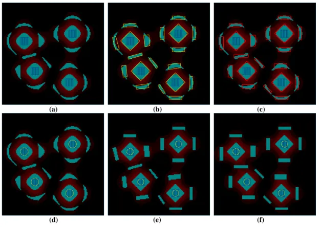
3.3 Mask simplification example
As described in section 2.4, the ILT-generated masks are transformed into simple rectangles based on central moments. Figures 5(a) to 5(c) demonstrate the procedure. Figure 5(a) shows the original mask of four semi-isolated vias. The simplified features are represented in yellow lines overlaying the original mask shown in Fig. 5(b). Figure 5(c) shows the final features snapped to 45-degree and axis-aligned line segments.
Some points to note in Fig. 5(c) are that the SRAFs sandwiched by two vias on the left side is relatively small due to limited space but still present. Also, there are a few SRAFs that would probably not have been generated with a simple rule-based procedure. For example, the 45-degree SRAF for the bottom via which our algorithm placed instead of a vertical SRAF which would be the obvious rule-based placement. We believe that this particular orientation is caused by a conflict resolution with the lower-left via, which also has a 45-degree SRAF instead of a vertical one.
Finally, the impact of the mask simplifications on contours are shown in Fig. 5(d) to 5(f) for masks approximated from Fig. 5(a) to 5(c), respectively. The printed contours are smaller in shape than the original due to a conservative transformation from the automatically generated features. This is not a fatal flaw, however, as the mask simplification is only a pre-OPC output; the contours can be fine tuned later by the OPC correction of the main features.
(a) (b) (c)
(d) (e) (f)
Fig. 5. ILT-generated masks are transformed into simple rectangles based on central moments. Figure 5(a) shows the original mask of four semi-isolated vias. The simplified patterns are represented in yellow lines overlaying the original mask shown in Fig. 5(b). Figure
5(c)shows the final features snapped to 45-degree and axis-aligned line segments. The impact of mask simplifications on contours are
4. Conclusion
In conclusion, we have demonstrated an innovative pixel-flipping technique for inverse lithography. By incorporating wavefront-expansion and damping techniques, we show that the generated mask patterns are suitable for applications of model-based SRAF generation and placement. In this approach, the drawn patterns receive a model-based sizing with surrounding SRAFs, which are computed simultaneously in a single iteration. Our method generates compact SRAFs only near drawn features, which could be helpful in reducing tile stitching if applied at a full-chip scale. Finally, we demonstrate that the ILT-generated masks can be simplified into polygons using central moments. The insertion of ILT in the pre-OPC stage results in minimal impact to the existing flows.
REFERENCES
[1] B.E.A. Saleh and S.I. Sayegh, “Reductions of errors of microphotographic reproductions by optical corrections of original masks”, Optical Eng. 20 pp 781-784 (1981).
[2] K.M. Nashold and B.E.A. Saleh, “Image construction through diffraction-limited high-contrast imaging systems: an iterative approach”, J. Opt. Soc. Am.A, 2 p. 635 (1985).
[3] Yuri Granik, “Fast pixel-based mask optimization for inverse lithography,” J. Microlith., Microfab., Microsyst. 5, 043002 (2006).
[4] S.-H. Jang et al., “Manufacturability evaluation of model-based OPC masks,” Proc. SPIE 4889, 520–529 (2002). [5] A. Rosenbluth et al., “Optimum mask and source patterns to print a given shape,” J. Microlithogr., Microfabr.,
Microsyst. 1, 13–30 (2002).
[6] R. Socha et al., “Contact hole reticle optimization by using interference mapping lithography _IML_,” Proc. SPIE
5446, 516–534 (2004).
[7] D. C. Sorensen, “Newton’s method with a model trust region modification,” SIAM (Soc. Ind. Appl. Math.) J. Numer.
Anal. 19, 409–426 (1982).
[8] D. Luenberger, “Linear and nonlinear programming,” Kluwer Academic Publishers, Norwell, Mass. (2003). [9] S. I. Sayegh, “Image restoration and image design in non-linear optical systems,” PhD Thesis, Univ. of Wisconsin,
Madison (1982).
[10] M. Minoux, “Mathematical programming,” in Theory and Algorithms, Wiley, New York (1986).
[11] N. B. Cobb, “Fast optical and process proximity correction algorithms for integrated circuit manufacturing,” PhD Thesis, Univ. of California at Berkeley (1998).
[12] M. Born and E. Wolf, Principles of Optics, Pergamon Press, sixth ed., pp. 528-532 (1980).
[13] Alfred Kwok-kit Wong, Optical Imaging in Projection Microlithography, SPIE PRESS, Bellingham, Washington USA, pp. 63-70, (2005).
[14] Nicolas Bailey Cobb, “Fast optical and process proximity correction algorithms for integrated circuit manufacturing,” University of California at Berkeley, Berkely, California, (1998).
[15] Y. Liu and A. Zachor, “Optimal binary image design for optical lithography,” Proc. SPIE 1264, 401–412 (1990). [16] Y. Liu and A. Zachor, “Binary and phase-shifting image design for optical lithography,” Proc. SPIE 1463, 382–399
(1991).
[17] J. Flusser and T. Suk, "Rotation Moment Invariants for Recognition of Symmetric Objects," IEEE Trans. Image