A Programmable Transceiver Structure of Multi-rate OFDM-CDMA for
Wireless Multimedia Communications
Po-Wei Fu
Department
of
Electronical Engineering and
Graduate Institute
of
Communication Engineering
National Taiwan University, Taipei, Taiwan, R.O.C.
[email protected]
Abstract
TIVO multi-rate transmission schemes, multi-code (MC) and
variuhle-spreading-length (VSL) code, for realizing niultiniediu communications on three @pes of OFDM-CDMA systems are proposed. We integrate them into a programmable structure such that the operation can be controlled and adjusted by system parameters and thus the transceiver can be used in dif'lirrent systems without chan&g the fundamental hardware and sofmare architecture, which serves the trend of sojtware-radio for ,fiture application.
1. Introduction
Multimedia communication will be the main stream in the future communication services and it introduces challenges in effective transmission. As code-division multiple-access (CDMA) being utilized for the third generation and future communication systems, it is an important subject to realize multimedia services
based on CDMA. Based on previous research, Multi-Code (MC)
and Various-Spreading-Length (VSL) access schemes are the two
most fundamental and widely applied multi-rate schemes [l]. On
the other hand, Orthogonal-Frequency-Division-Multiplexing (OFDM) has been widely used in high-speed digital
communications, which can be implemented efficiently by the
digital technique of Fast-Fourier-Transform (FFT)[2] and known
as a solution to combat the problem of the highly hostile mobile chaunels in high-speed transmissions. Furthermore, combining CDMA and OFDM results in finer partition of radio resource, which makes the resource allocation more effective. Therefore,
OFDM-CDMA for multimedia applications is an attractive
candidate for the 4th generation wireless communication systems
and its realization by a flexible sofnn-are-defined architecture is of
significant interests. Recent years, multiple access schemes based on the combination of CDMA and OFDM have been proposed,
and they can be generally divided into three types, namely MC-
CDMA, MC-DS-CDMA, and MT-CDMA respectively [3]. To
realize multi-data-rate transmission, we separately proposed two
transmission methods, based on MC and VSL strategies, for the
three OFDM-CDMA scenarios. Besides, we design a transceiver architecture accommodating these six multi-rate OFDM-CDMA R.O.C. and by the Integrated Progmmable Communications, Inc.
*This research is supported in part by Ministry of Education, Taiwan,
Kwang-Cheng Chen
Department of Electrical Engineering and
Graduate Institute
of Communication Engineering
National Taiwan University, Taipei, Taiwan, R.O.C.
[email protected]
I942
scenarios and show its programmability such that system operation can be controlled and reconfigured by adjusting parameters in software. It supports the accommodation in different systems with only one fundamental hardware and software architecture.
2.
Multi-Rate OFDM-CDMA Systems
Assume there is a basic data rate supported in systems and the data rate o f each user is an integer multiple m of the basic data
rate, said a user with rate m. The detailed structures of the multi- rate (MR)-OFDM-CDMA systems are described in the following.
In transmitting aspects,
(1) Multi-rate M C - C D U
a.MC access
The data stream of a user with rate /n is first multiplexed into m different streams with basic rate and then
each is
treated as an individual (effective) user with individual spreading codes. Aftermultiplexing, each stream is serial-to-parallel (UP) converted to P
outputs, where the number of sub-carriers in the system depends
on P. For frequency-domain spreading, symbols on each output is
copied iuto F branches, where F is the constant spreading factor
o f the spread spectrum operation in the system and the signal at
each sub-stream is then multiplied by the corresponding bit of the
spreading codes. Thus, there are
PF
parallel outputs of eacheffective user after the frequency domain spreading. After
combining all the PF parallel outputs from other users, they are
transmitted by PF orthogonal carriers correspoudiigly, where
Inverse Discrete Fourier Transform (LDFT) can perform this
modulation on orthogonal carriers equivalently. Label the
effective users as user 1,2,.
.
.,
and the transmitted BPSK signal of a system containing IM data rates in baseband isx ( f ) =
-&kbbAck,f?J2? k=l PI (I0
I tI
PT, ,
(1) Uwhere K =
mK,
is the number of total effective users, b b isthe pth symbol of the kth effective user, and AL is the transmitted
amplitude of the kth effective user. Af
fp,,+,
-,f,,f
= ,&9,where
T,
is the symbol duration of the data stream with basicm=l
then..spxac..by. the..same..spreading ..codes . and transmitted .via..
different sub-carriers. Thus, the number of sub-carriers in transmission is generally PL. The transmitted signal is,
x(t)= ~ ~ ~ , b , , ~ c ~ q ( t
- JT,
&ej2@+', 0 < t <PT.,
(3)MK, is the number of effective users, and p(t
)
is. . .
K P F
k=l pi J = I /=I
M
where
K
=the unit-rectangular function with duration T,, and
Af
=F/
m=l
P T s '
rate before S/P conversion.-ew E fk1)denotes t h e m bit ofthe
spreading codes used by the kth effective user.
u.ku* -,I
R g Ila) Mulh-Code Access ofMuln-Xa~c UC-CDM.4
b. VSL access
The data stream from a user with rate in is directly SIP
converted into Pnr sub-streams, where the number of sub-carriers
in the system is still PF as in MC access. Symbols on each sub-
stream are copied into F/m branches and then the symbols on each
branch are multiplied by the corresponding bit of spreading codes. Note that F/m should be chosen as an integer in our system design.
Regardless any dare rate, there are totally PF parallel signal
outputs after such fiequency domain spreading. Combining all the
PF parallel signals From other users, they are transmitted by
orthogonal carriers. The bandwidth of each sub-carrier and the
overall occupied bandwidth are the same as in MC access. The
transmitted signal in a VSL system containing M data rates is
: ?
rfknr.uaj+r P
Yiy 2(.) Mdh-Cndr Ai-m*l U T M r - I I I C W A
b. VSL access
Regardless any date rate, the data stream of each user is
directly S/P converted into P sub-streams. If the user is with rate
mi, each sub-stream is spread with factor F/nz by cyclically
multiplying the same spreading codes. Combining all the
P
parallel signals form other users, they are trausmitted via
orthogonal carriers. Also note that if the transmission diversity is expended with a factor L, each sub-stream before spreading stage
should be copied into L identical branches and these data-streams
fkom the same user are then spread by the same spreading codes and transmitted by different sub-carriers The number of sub-
carriers in transmission is still generally
PL.
The trausmittedsignal is
m=1 klp 4 I
where
K,,,
denotes the number of users with rare m, h,, is thepthsymbol of the kth user with rate m, Ad is the transmitted
amplitude, and Af
=
.
c , , ~ E {k 1) denotes the@ bit ofthe spreading codes used by the kth user with rate m.
( r s n n w x u m n ) 0
s t <
PTs
7 (4)where K,,, is the number of users with rate m and Af =
ypT,.
I@) \inahle-SpmAvylengdi Axes o f M bRate MC CDMA (2) Mirlti-rate MC-DS-CDMA
a. MC access
The data stream of rate ni is first multiplexed into m different
streams with basic rate and each is treated as an individual
(effective) user with individual spreading codes. Each stream is then S P converted into
P
parallel sub-streams, whereP
is thenumber of sub-carriers in transmission. At the spectrum-spreadiug
stage, the sub-streams from the same effective user are spread by
the same spreading codes with factor F via cyclically multiplying
the codes. Combining all the
P
parallel spread signals fiom othereffective users, they are transmitted by orthogonal carriers correspondingly. Note that if the system adopts the strategy in [5] to expend the transmission diversity with a factor L, each sub-
stream before spreading stage should be copied into L identical
branches and these data-streams from the same effective user are
U
P
P
Fig a%) WUDleSprcadlng-Lengtl~ A-* nf MC-DS-CDUA
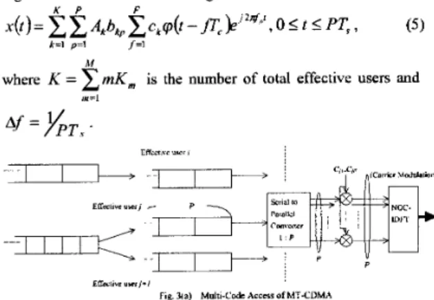
(3) Multi-rate MT-CDMA a.MCaccess
The data stream of rate m is first multiplexed into m different
streams with basic rate and each is treated as an individual
(effective) user with individual spreading codes. Each streams is
then SP converted to P outputs, where P is the number of sub-
carriers in the system. The
P
parallel outputs i?om the sameeffective user are spread with factor F by identical spreading
codes via cyclical multiplying the codes. Unlike in MC-DS-
CDMA, &er combining all the
P
spread signals from other users,they are transmitted by carriers whose implicit orthogouality
exists corresponding to the signals before spreading. NOC-IDFT
(see Appeudix) performs this modulation equivalently instead of regular IDFT. The transmitted signal is
M
where K = CtnK,,, is the number of total effective users and
,H=l
rffccli\c wr8
. .
E U ~ l t v r u u r j
--=
ELTall". "=/+/ Fig. 3 ~ ) Multi-Codc AceersofMTCDMAb. VSL access
The data stream from a user regardless any rate is SP
converted into
P
parallel sub-streams, whereP
is the number ofsub-carriers in the systems. Signal at each sub-stream is spread with factor Fhn by cyclical multiplying the spreading codes. Afier combining all the
P
spread signals &om other users, they are transmitted by carriers, where the implicit orthogouality exists between signals before spreading. The transmitted signal ism=1 k=l g=I p=l
0 5 t 5
PT,
,
(6)where K,, is the number of users with rate n1 aud
Af
=)/pT,
. c.,.c.Low-Raw w i
7
P
Rg. 3(b) V m a b l e - S ~ m g - L m @ b Accers of MT-CDMA
Tn receiving aspect, a general structure is illustrated as Fig. 4.
In general, the receiver perfom inverse functions corresponding
to those in the transmitter.
Fig 4 TI= geeneirl receiving )tmcwc of MR-OFDM-CDM4
The detailed architectures and functions of different scenarios are
described in the following sections for both transmitter and receiver in programmable design.
3. Programmable Architecture
Programmable OFDM-CDMA transmitterTwo multi-rate access strategies and three OFDM-CDMA
methods result in totally six multi-rate OFDM-CDMA scenarios. The proposed architecture of programmable transmitter is depicted in Fig. 5 , which also shows the control functions, F I-F6, that should be executed in operation. Each function can be adjusted by some parameters, which includes: choice of access scheme, choice of adopted OFDM-CDMA scheme, data rates, and the spreading factors of each data stream. These fuuctions are defined as:
F1: It determines the number of enabled Main Branches
(MB).
Itis executed on a multiplexer after receiving the data stream from a
user. If the system is operated on multi-code access mode, it multiplexes the data stream into m sub-streams by enabling m
branches. If it operates on VSL mode, just forward the data
stream on one branch.
F2: It determines how many Parallel Output Branches (POB)
correspouding to the SE' ratio will be enabled. Only under the
scenario of VSL-MC-CDMA, POB is set to be mP, otherwise,
POB is P .
F3: Function 3 determines the number of enabled Sub-Branches
(SB), which is a copy of the former stream, of each POB and the type of spreading. If the scenario is MC-CDMA, the enabled SB
is F for multi-code access and Flm for VSL access. If the scenario
is MC-DS-CDMA and MT-CDMA, SB is L and 1 respectively for
both access methods. Cyclical multiplying by corresponding
codes on each SB is set for MC-DS-CDMA and MT-CDMA. In
MC-CDMA mode, signal on each SB is spread by multiplying
one corresponding bit of spreading codes.
F4: To satisfy the required number of parallel inputs for JFFT
operation, fuuction 4 pads zeros accordiug to the selected scenario,
which results in regular padding for regular IFFT and circular-
shifi padding for NOC-TFFT. The circular period is F in MC
mode and F/m in VSL mode. In example of radix-2 algorithm, the
number of Padded Zeros (PZ) should be 2r'0g1.vb1 -Nh in regular
IFFT, where Nb denotes the number of parallel inputs. For NOC-
E F T operation in MT-CDMA modes, PZ should be
F(2r1082 N h l
-
N ,)
and allocated in circular-shift type.F5: Function 5 decides the number of operation points (OP) in
IFFT for each scenario. OP equals the number of outputs in F4.
F6: Function 6 determines the enabled input branches of the PIS converter and the conversion ratio at different scenarios.
- J
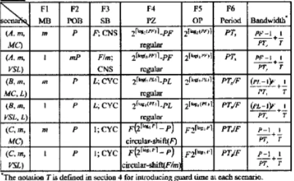
Table 1 summarizes the parameters of Fl-F5 in different
scenarios, the operation period in F6, and the resultant bandwidth.
The involved notations are defined as:
MC: multi-code, VSL Variable-Spreading-Length
m: data rate in unit of basic rate
F: spreading factor of a basic data-rate user
L : the diversity expansion of MC-DS-CDMA
CNS: constant bit multiplying, CYC: cyclical multiplying
A: MC-CDMA, B: MC-DS-CDMA, C: MT-CDMA
'The oolauw 7 is delinrd in srcuon 4 for hwoducing -pard lime ai each "io.
According to the scenario selection, appropriate parameters and
subroutines are chosen and adjusted to perform these functions by
micro-controller or by DSP. Briefly speaking, these parameters
determine the number of enabled hardware branches, the diversity
in transmission, zero padding, the time-domain or frequency-
domain spreading, and the spectrum profile.
Pi-ogrankable OFDM-CDMA receiver
The same as transmitting, there are six receiving variations
should be accommodated for six system scenarios. A software- based Rake receiver is illustrated in Fig. 6. Due to the principle of OFDM transmission, the number of sub-carrier is generally
selected that signals on each sub-band suffer fiom frequency-
nonselective fading. Therefore, only one finger is sufficient for
most cases. However, there may be some situations that the fading in sub-bands is hard to be maintained Frequency-
nonselective. Thus, the number of tumed-on fingers could be a
pre-defined value
or
is controlled by the result of channelestimation to combat multi-path effect. The delays between fingers are also adjusted according to the estimation result. Fig.7 depicts the programmable structure of the fingers, where eight
functions, FI-F8, are defined. The decision of symbol detection
could be used for next step synchronization if the precision is high
enough. These hnctions are defined as:
F1: It controls the sample rate of the received signals according to
the selected scenario, including the required number of input in
the following FFT.
F2: Function 2 determines the ratio of S/P conversion and the
number of parallel outputs (PO) according to the selected scenario.
F3: Function 3 decides which type of FFT will be executed. It
consists of two sub-functions where the fmt performs circular-
shift zero padding for MT-CDMA modes and the second
determines the operation points of FFT device, General FFT
operates in NOC form for MT-CDMA modes and in regular form
for MC-CDMA and MC-DS-CDMA modes by disabling the
fxst
sub-function. (See Appendix)
F4: Function 4 controls the filtering of samples after FFT to
discard the signals out of the sub-bands and determines the
enabled tapped-delay-lines. The pass window (PSW) of zero
forcing equals the number of sub-carriers used in transmission.
F5: Function 5 is executed in the dispreading stage such that each
output of F4 is despread according to the spreading type (constant
or cyclic type) of the selected scenario by multiplying the
corresponding codes. The despreading structure is a tapped-delay-
line (TDL) form and the number of enabled TDL equals ZFW in
F4. F5 determines the number of enabled tap (ET) and the time
spacing (TS) of each tap. For MC-CDMA modes, only one tap is
needed and each line corresponds to one bit of the spreading
codes. For MC-DS-CDMA and MT-CDMA modes, the number
of taps in each line equals the spreading factor.
F6: Functions 6 determines the sampling rate (SR) for taking
samples on each line at the dispreading stage. The sampling rate
equals the OFDM symbol duration.
F7: Based on the collection of samples from each line of all
fingers, the detector makes symbol decision by combining these diversities. Different combining methods could be applicable in this stage by DSP.
FE: It controls the de-multiplexing in multi-code mode to reconstruct the original data sequence fkom the effective streams.
Clunnel E~umarton **IC
4.
Implementation Issues
The software architecture of the proposed programmable multi- rate OFDM-CDMA transceiver can be realized by the general
hardware structure in [4] as an extension. Different scenarios
have different requirement of bandwidth and sampling rate. Due
to the accommodation of the six multi-rate OFDM-CDMA
scenarios, it forces the specification of the D/A converter and the
low-pass filter should satisfy all the requirements. Thus, the D/A
converter should support input rate higher than any possible sampling rate and the bandwidth of the low-pass filter should accommodate all scenarios. Another practical issue is the peak-to-
average power (PAP) ratio problem, which causes the inefficiency
of power amplifiers i11 RF. The PAP problem exists inherently iu
OFDM systems and can be reduced by techniques such as signal distortion, error correcting, and scramblkg [6]. However, the introducing of multi-rate traffjc challenges the power AMP severer. Among these scenarios, multi-code access may cause
larger instant power due to its concept of parallel transmission.
Therefore, we should select a power AMP whose linear range
could accommodate the largest requirement o f multi-rate
transmission under the aid of PAP reduction mechanisms.
To eliminate the der-symbol interference and inter-carrier
interference, a guard time
T,
which is larger than the multi-pathspread of channels, should be added on each OFDM symbol after
P/S conversion in the transmitter and the corresponding removing
should exist before F1 in the receiver. ARer cyclic guard time
extension, the OFDM symbol duration Twill be PTs+Tg in MC-
CDMA, and PTs/F+Tg in MC-DS-CDMA and MT-CDMA. In addition, to improve the performance, some techniques such as
forward error control (FEC) and interleaving could be easily
added to this structure without any difficulty.
Although our design focuses on multi-rate applications, this architecture is backward conipatible to single rate OFDM-CDMA
systems by setting m=l, to DWCDMA systems by setting
P=L=l
in MC-DS-CDMA mode, and to conventional OFDM systems by
setting F=L=I in single user case. Due to the occupied bandwidth
of each OFDM-CDMA systems is kept fixed for users of any rate
in both MC access and VSL access modes, multi-rate applications
do not increase the requirement on some hardware devices, such
as the sampling rate of A/D and the bandwidth of low-pass filter.
Processing delay is a major challenge in OFDM systems,
especially sensitive in real-time applications. In fact, this
programmable transceiver supports the possibility that the number
of subcarriers could be adjusted dynamically according to the
channel conditions such that the least sub-carriers attain frequency-nonselective fading at each sub-channel. In the same
way, delay-sensitive data transmission is realizable by reducing
the number of sub-carriers with the aid of more fingers in Rake receiving.
5.
Conclusion
We developed a transceiver architecture o f multi-rate OFDM-
CDMA systems and showed its programmability such that the general system can operate under different scenarios with a common hardware structure and reconfigure by software implementation. The hture work shall be analyzing the performance of each scenario and figuring out its relationship with these adjustable parameters such that optimal resource
programming is realizable for future wireless multimedia
applications.
References
[I] T. Ottosson and A. Svensson, “Multi-rate schemes in DS/CDMA
systems”, Proc. IEEE Vehic. Tech. Cor$, pp. 1006-1010, 1995.
[2] K. F a d , S. Kaiser and M. Schiiell, “A flexible and high-performance cellular mobile communication system based on orthogonal multi-carrier
SSM.4,” Wireless Personal Communications, vol. 2, No. 1, pp. 121-144,
1995.
[3] Shinsuke Ham, Ranijee Prasad, “Oveniew of multicarrier CDMA,” IEEE Conirniinication Magazine, pp. 126-133, Dec. 1997.
[4] K. C. Clen and S.T. Wu, “A Programmable architecture for OFDM-
CDMA,” IEEE Ctm”icntion Magm’ne, pp. 76-82, Nov. 1999.
[ 5 ] Sourour, EA.; Nukuguwu, bf “Pcrfomiancc of Orthogonal Multicanicr CDMA in a Multi-path Fading Channcl”, IEEE Trunsactions on Communications, pp. 356 -361, March 1996.
[6] R. Van. Nee, and R Prasad, OFDM Jbr wireless nrultimediu contwzmicutiorrs, Artech House, 2000.
Appendix
NOC-IFFT
For the kth user, the transmitted signals after modulation is
P F I.‘
x k ( t ) = ~ b b ~ c l i f ~ ( t - j ~ . ) e J 2 “ ‘ = c x k , ( t ) , O 5 t 5 T,(A.l)
p = l /=I f = l
where Af
= f,+,
- f,
=I/.Ts
and the discrete equivalent formof xu (t)is: for n=l
-N,
where d,
b ] = b , c w .
Dejinifion:
N point NOC-IDFT of a sequence s [ i ] , i=l-N, where
N I
N ,
=F E N
is generated bv( I ) , At lth sub-period, for I = I . 2
,...,
F. 2- ( I - I ) N , ] ,
(I
- lws+
1I
iI
0
,
otheiwisewhere N , = N / F , n=I-N, and I-I-F.
Therefore, let N=FP and it can be easily shown that
where F{;N) denotes N-point regular DFT. Therefore, circular- shift zero padding aud regular FFT can implement NOC-FFT. Disabling of F4 goes back to regular EFT.
For receiving in MT-CDMA systems as [ 5 ] , we define the NOC-
FFT corresponding to NOC-TFFT. Let r ’ [nl n = 1
-
N, be the circular-shift zero padding for r[n],Dqfinition:
Fpoints NOC-DFT oftfn],
n=l-N,
,iss,
[i3=
F,,,.{r[I].
.
. r [ X J F , f }
=2
r s[n]..p(-
j 2 Xi%)
, n=(j.-l),V,+Ii=I-N, , where
iV,
= Ar I F EN
.By the same principle, it can be shown that circular-shift zero padding and regular FFT can also implement NOC-FFT.
Therefore, sampling
4t)
with rate N/FTc and taking F-pointNOC-FFT with period Twill get the desired result. I