A Complementary Codes Pilot-Based
Transmitter Diversity Technique for OFDM Systems
Meng-Lin Ku and Chia-Chi Huang
Abstract— This letter presents a complementary codes pilot-based space-time block code / orthogonal frequency division multiplex (STBC/OFDM) system. In this system, a pair of complementary codes transmitted in a pre-defined order with the OFDM data signals is used as the pilot signals in a two-antenna transmitter diversity system, and used to estimate the channels for optimal data detection at the receiver side. A complete receiver architecture has been designed and Monte Carlo simulations have been used to verify the performance of the system in mobile radio fading channels.
Index Terms— Complementary codes, space-time coding, or-thogonal frequency division multiplex, channel estimation.
I. INTRODUCTION
I
N a recent paper, space-time block code (STBC) [1][2] has been suggested to improve the performance of an orthogonal frequency division multiplex (OFDM) system [3]. Garg [4] studied the degradation in the performance of the STC with imperfect channel estimation. In general, channel estimation is an important issue in realizing a successful STBC/OFDM system. We all know that channel estimation can be performed at a receiver by inserting pilot signals into transmitted signals. There are several factors which have to be considered for the practical use of pilot signals in multiple transmitter antenna systems. First, pilot signals should be sent in the same frequency band and at the same time with data signals to ensure the accuracy of channel estimation. Second, multiple channel state informations (CSIs) must be derived from the received signal in a system with multiple transmitter antennas. To estimate multiple channels, transmitter antennas can alternately transmit a single pilot signal or simultane-ously transmit different pilot signals which have impulse-like auto-correlation and zero cross-correlation properties [5]–[8]. Third, the length of pilot signals should not be too short in order to achieve accurate channel estimation. In some special cases, pilot signals take the length of 2P, where P is aninteger, to meet with the requirement of fast signal processing algorithms. Finally, the values of pilot signals need to be taken from some predetermined signal sets such as {1, −1, j, −j} to maintain constant amplitude and avoid the non-linear effect of an amplifier. The design of optimal pilot signals is an open problem [5] –[12]. Computer simulations are used in [5]–[8] to
Manuscript received Nov. 24, 2001; revised July 1, 2004 and November 10, 2004; accepted February 18, 2005. The editor coordinating the review of this paper and approving it for publication is I. B. Collings.
M. L. Ku is with the Department of Communication Engineer-ing, National Chiao Tung University, Hsinchu, 300, Taiwan (e-mail: [email protected]).
C. C. Huang is with the Department of Communication Engineer-ing, National Chiao Tung University, Hsinchu, 300, Taiwan (e-mail: [email protected]).
Digital Object Identifier 10.1109/TWC.2006.03005.
exhaustively search the pilot signals which are able to achieve MMSE channel estimation. [9] proposed a channel estimator based on the correlation of channel frequency response at adjacent frequencies. However, a large size of matrix inverse is required in this scheme. [10]–[12] extended the work in [9] to reduce the complexity of channel estimation.
In this letter, we suggest that complementary codes (CC) can be used as pilot signals and transmitted in time domain for the purpose of channel estimation in a two transmitter antenna system. The CC pilot signals satisfy the requirements of pilot signals we mentioned above, and at the same time, have the minimum peak-to-average power ratio (PAPR). We will describe the functional block diagrams and simulate the performance of a STBC/OFDM system with CC pilot signals. The rest of this letter is organized as follows. In Section II, we will describe the CC pilot signals for a two transmitter antenna system. In Section III, We will introduce the transmitter architecture of a CC pilot-based STBC/OFDM system. The details of the receiver operation such as signal detection, channel estimation, etc., are described in Section IV. In Section V, we show our computer simulation and performance evaluation results. Finally, conclusions are drawn in Section VI.
II. CC PILOTSIGNALS FOR A
TWOTRANSMITTERANTENNASYSTEM
Binary CC were originally conceived by Golay for infrared multi-slit spectrometry applications [13]. More recently, these codes were also used in OFDM systems to reduce PAPR [14]. We can define CC as follows. Let us consider a pair of equally long sequences {α[n]} and {β[n]}, for 0 ≤ n ≤ N − 1, where
N is the length of the two sequences. These sequences are
called CC if their auto-correlations satisfy the relationship: Γ[n] ≡ N −1X m=0 {α[m]α∗[((m − n)) N] +β[m]β∗[((m − n)) N]} = 2N · δ[n] = ½ 2N , n = 0 0 , n 6= 0 (1)
where (·)∗ denotes the complex conjugate operation, ((·)) N
denotes the modulo N operation, and δ[n] is the Kronecker delta function.
The pilot signals of a two transmitter antenna system can be constructed from a pair of CC. For simplicity, we assume that CC sequences {α[n]} and {β[n]} are normalized such that their combined auto-correlation value Γ[n] = δ[n] as shown in Eq.(1). Consider a system with two transmitter antennas and
one receiver antenna. Two signals {α[n]} and {−β[n]} are simultaneously transmitted from the two transmitter antennas over two independent frequency selective fading channels in the first time slot; the other two signals {β∗[((−n))
N]} and
{α∗[((−n))
N]} are then simultaneously transmitted over the
same two channels in the second time slot. Furthermore, a cyclic prefix is added before each transmitted pilot signal to avoid inter-symbol interference (ISI) and to preserve the circular convolution between the pilot signal and the channel impulse response in the time domain. Here, we assume that the two channels are quasi-static over the two transmission time slots. Hence, the received pilot signals in the frequency domain in the first and second time slot, RT 1[k] and RT 2[k],
can be expressed as · RT 1[k] RT 2[k] ¸ = · Pα[k] −Pβ[k] P∗ β[k] Pα∗[k] ¸ · H1[k] H2[k] ¸ + Z[k] = P[k] · H1[k] H2[k] ¸ + Z[k] (2)
for 0 ≤ k ≤ N − 1, where H1[k] and H2[k] are the channel
frequency responses from the two transmitter antennas to the receiver antenna, Pα[k] and Pβ[k] are the N -point discrete
Fourier transform (DFT) of the CC sequences {α[n]} and
{β[n]}, P[k] is called a pilot matrix which is a Unitary matrix,
and Z[k] is an additive white Gaussian noise (AWGN) vector with zero mean and covariance matrix σ2
nI, where I is a 2 × 2
identity matrix. The received pilot signals are then multiplied by a matrix PH[k], where (·)Hdenotes the complex conjugate
transpose operation, to obtain estimated CSIs in the frequency domain · ˆ H1[k] ˆ H2[k] ¸ = PH[k] · RT 1[k] RT 2[k] ¸ = · H1[k] H2[k] ¸ + PH[k]Z[k] (3) for 0 ≤ k ≤ N − 1. As a result, the mean square error (MSE) of channel estimation is given by
M SE = E[( ˆHj[k] − Hj[k])2]
= σ2
n, j = 1, 2 (4)
Generally speaking, the pilot matrix can be any unitary matrix which satisfies the power constraint of |Pα[k]|2 +
|Pβ[k]|2 = 1 for all k. For example, |Pα[k]|2 = |Pβ[k]|2 =
1/2 for all k also satisfies the unitary matrix requirement. However, the CC pilot signals used in this letter have the minimum PAPR (= 0dB) in time domain, thus improve radio frequency (RF) power amplifier efficiency. In the case of |Pα[k]|2 = |Pβ[k]|2 = 1/2 for all k, the PAPR is
10log2N (dB).
III. CC PILOT-BASED
STBC/OFDM TRANSMITTERARCHITECTURE
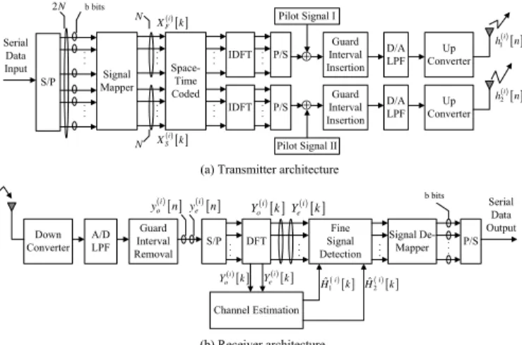
The transmitter block diagram of a CC pilot-based STBC/OFDM system is shown in Fig. 1(a). The block diagram shows two transmitter antennas. The transmitted signal from each antenna consists of a data signal and a pilot signal. Now we describe the generation of the data signals. At the output
S/P MapperSignal IDFT Space-Time Coded Serial Data Input b bits IDFT P/S P/S Guard Interval Insertion Guard Interval Insertion D/A LPF D/A LPF Up Converter Up Converter ⊕ ⊕ Pilot Signal I Pilot Signal II ( )i[ ] F X k ( )i[ ] S X k ( )[ ] 1 i h n ( )[ ] 2 i h n Down Converter A/D LPF Guard Interval Removal S/P DFT Fine Signal Detection Channel Estimation Signal De-Mapper P/S Serial Data Output ( )i[ ] ( )i[ ] o e y n y n ( )i[ ] ( )i[ ] o e Y k Y k ( )i[ ] o Y k Ye( )i[ ]k ( )[ ] 2 ˆi H k ( )[ ] 1 ˆi H k (b) Receiver architecture (a) Transmitter architecture 2N
N
N
b bits
Fig. 1. CC pilot-based STBC/OFDM systems.
of the signal mapper, the ith block of 2N data symbols d(i)[k]
are separated into two data sub-blocks and represented as
XF(i)[k] = d(i)[k]
XS(i)[k] = d(i)[N + k] (5) for 0 ≤ k ≤ N −1, where N denotes number of subcarriers in an OFDM symbol, XF(i)[k] and XS(i)[k] are the kth data sym-bol of the first and second data sub-block, respectively. Here, we use Alamouti’s STBC encoding method [1] to encode the two data sub-blocks, XF(i)[k] and XS(i)[k], in the sequence as described in [3]. An N -point inverse DFT (IDFT) unit is used in each arm of Fig. 1(a) to transform the frequency domain data symbols into a time domain data signal. Afterward, we add the CC pilot signal as described in Section II to the time domain data signal. Both the data signal and the pilot signal are assumed to be of the same length and they are added synchronously to become an effective OFDM symbol with symbol duration T . The cyclic extension with time duration
Tg of an effective OFDM symbol is then inserted as a guard
interval to combat the ISI effect. Finally, a complete OFDM symbol with symbol duration T + Tg is converted into an
analog signal with a digital-to-analog (D/A) converter, filtered by a low-pass filter (LPF), up converted to RF band, and transmitted in air with a pre-selected antenna.
IV. CC PILOT-BASED
STBC/OFDM RECEIVERARCHITECTURE
The receiver block diagram of the CC pilot-based STBC/OFDM system is shown in Fig. 1(b). This receiver architecture consists mainly of a fine signal detection func-tional block and a channel estimation funcfunc-tional block, along with other common blocks. After a RF signal is received from an antenna, it is down converted to the equivalent baseband, low-pass filtered, and digitized. We assume that timing and carrier frequency synchronization are perfect and the length of the channel impulse response is not longer than the length of the guard interval. The channels are assumed to be quasi-static during any two successive time slots. The frequency response of the propagation channel between the first transmitter antenna and the receiver antenna is denoted by
( )i[ ] o Y k Ye( )i[ ]k ( )i[ ] e Y k ( )i[ ] o Y k X%S( )i[ ]k ( )[ ] ˆi F X k ( )[ ] ˆi S X k Pilot Signal Cancellation Combiner ML Decoder ( )[ ] 1 ˆi H k ˆ2( )[ ] i H k ( )i[ ] F X% k
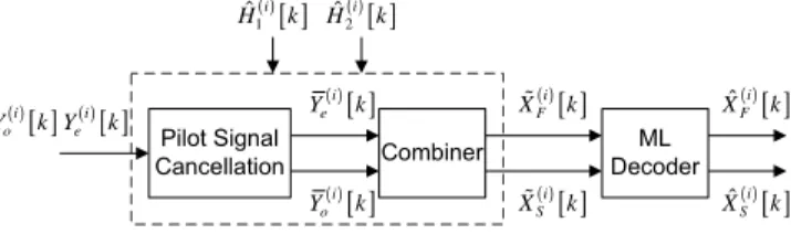
Fig. 2. Fine signal detection functional block.
Pilot Match ( )i[ ] e Y k ( )i[ ] o Y k Data Interference Cancellation ( )i[ ] e Y( k ( )i[ ] o Y( k ( )[ ] 1 i h n ( )[ ] 2 i h n Path Selection ( )[ ] 1 ˆi h n ( )[ ] 2 ˆi h n DFT ( )[ ] 1 ˆi H k ( )[ ] 2 ˆi H k Coarse Signal Detection ( )[ ] ˆi FC X k XˆSC( )i[ ]k Delay [ ]k P IDFT
Fig. 3. Channel estimation functional block.
H1(i)[k], and the other one is denoted by H2(i)[k], where index
i is used to indicate the corresponding (2i)th and (2i + 1)th
time slot. Hence, after the guard interval removal, serial-to-parallel (S/P) conversion and N -point DFT computation, the successively received signals Ye(i)[k] and Yo(i)[k] on the kth
subcarrier in the (2i)th and (2i + 1)th time slot can be represented as Y(i) e [k] = H (i) 1 [k](X (i) F [k] + Pα[k])
+H2(i)[k](XS(i)[k] − Pβ[k]) + Ze(i)[k]
Y(i)
o [k] = H1(i)[k](−X ∗(i)
S [k] + Pβ∗[k])
+H2(i)[k](XF∗(i)[k] + Pα∗[k]) + Zo(i)[k] (6)
for 0 ≤ k ≤ N − 1, where Ze(i)[k] and Zo(i)[k] are the AWGN
in the (2i)th and (2i+1)th time slot, respectively. The noise in each time slot is modeled as an independent complex Gaussian random variable with zero-mean and variance σ2
n.
A. Fine Signal Detection
Fig. 2 shows the details of the fine signal detection func-tional block which include a pilot cancellation unit, a combiner unit and a maximum likelihood (ML) decoder unit. We assume that the estimated CSIs are accurate, i.e. ˆH1(i)[k] = H1(i)[k];
ˆ
H2(i)[k] = H2(i)[k], and the pilot interference signals can thus be reconstructed and be completely subtracted from the received signals Ye(i)[k] and Yo(i)[k]. The output of the pilot
signal cancellation unit can be expressed as ¯
Ye(i)[k] = H1(i)[k]XF(i)[k] + H (i) 2 [k]XS(i)[k] + Ze(i)[k] ¯ Y(i) o [k] = −H (i) 1 [k]X ∗(i) S [k] + H (i) 2 [k]X ∗(i) F [k] + Zo(i)[k] (7) for 0 ≤ k ≤ N − 1. We then use the combiner unit to combine the received signals from different transmitter antennas according to the method revealed in [3]. Finally, in the ML decoder unit, the ML decision rule [1] can be used to detect the transmitted data symbol on each subchannel.
B. Channel Estimation
Fig. 3 depicts the detailed structure of the channel estima-tion funcestima-tional block. First, we use a coarse signal detecestima-tion unit to obtain coarsely estimated data symbols ˆXF C(i)[k] and
ˆ
XSC(i)[k] by using the estimated CSIs in the previous two time slots, i.e., the (2i − 2)th and (2i − 1)th time slot. The structure of the coarse signal detection unit is similar to the fine signal detection functional block as shown in Fig. 2. The data interference signals are then reconstructed and subtracted from the received signals Ye(i)[k] and Yo(i)[k] in a
data interference cancellation unit. We assume that the data interference signals can be cancelled perfectly and the refined signals can be represented as
˘
Ye(i)[k] = H1(i)[k]Pα[k] − H2(i)[k]Pβ[k] + Ze(i)[k]
˘ Y(i) o [k] = H (i) 1 [k]Pβ∗[k] + H (i) 2 [k]Pα∗[k] + Zo(i)[k] (8)
for 0 ≤ k ≤ N − 1. Next, the refined signals are multiplied by the complex conjugate transpose of the pilot matrix P[k] in the pilot matching unit in Fig. 3, to obtain more accurately estimated CSIs in the frequency domain. We then use an N -point IDFT unit to obtain the estimated CSIs in the time domain, i.e.,
¯h(i)
1 [n] = h (i)
1 [n] + IDF T {Ze(i)[k]Pα∗[k] + Zo(i)[k]Pβ[k]}
¯h(i)
2 [n] = h (i)
2 [n] + IDF T {−Ze(i)[k]Pβ∗[k] + Zo(i)[k]Pα[k]}
(9) for 0 ≤ n ≤ N − 1. Finally, a path selection unit is used to suppress the noise effect and to refine the estimated CSIs. For path selection, we first define a parameter Np, which is
the desired number of paths to be selected. Only the Nppaths
with larger amplitudes in ¯h(i)1 [n] (or ¯h(i)2 [n]) are preserved and all the other paths are discarded. As a result, we obtain ˆh(i)1 [n] and ˆh(i)2 [n] in the following way:
ˆh(i) j [n] = ¯h(i) j [n] , if |¯h (i) j [n]| is one of the Np larger values 0 , otherwise (10) for 0 ≤ n ≤ N − 1; j = 1, 2.
To initialize the channel estimator, pilot preambles without data signals added are transmitted in the first two time slots. The received signals are passed only through the pilot match-ing and the path selection unit to generate the preliminary channel estimations.
C. Receiver Complexity
The complexity of the CC pilot-based STBC/OFDM re-ceiver will be calculated in this subsection. Either N -point DFT or IDFT needs DF T N multiplications per OFDM symbol. At the recever, three DFT or IDFT operations are needed for every OFDM symbol (see Figs. 1-3). According to Fig. 2, the pilot signal cancellation unit and the combiner unit need 8N multiplications for every two OFDM symbols. In Fig. 3, the data interference cancellation unit and the pilot matching unit also need 8N multiplications for every two OFDM symbols. Furthermore, the coarse signal detection
TABLE I
SIMULATION PARAMETERS
Modulation OFDM & BPSK Carrier frequency 2 GHz
Total bandwidth 5.12 M Hz Number of receiver antennas 1
Number of subcarriers 256 Useful symbol time 50 µs
Guard interval 12.5 µs Transmitted data signal energy/ antenna 0.5
Pilot signal energy/ antenna 0.5 Vehicle speed 8, 30, 120 km/hr Delay of multipaths 0.19 µs ∼ 9.77 µs
unit requires the same number of multiplications as the fine signal detection functional block, i.e. 8N per two OFDM symbols. Hence, the receiver has the complexity order of 3DF T N + 12N multiplications per OFDM symbol.
V. COMPUTERSIMULATIONRESULTS
We utilize computer simulations to verify the performance of the proposed CC pilot-based STBC/OFDM system in a two-path fading channel and a Universal Mobile Telecom-munications System (UMTS) defined channel. The equivalent baseband impulse response of the two-path fading channel is represented by
h(t) = a1δ(t) + a2δ(t − τ ) (11)
where δ(t) denotes a delta function, τ is the excess delay of the second path, and al is the complex gain of the lth
path, which is generated from the Jake’s fading channel model [15]. Besides, the channel selected for evaluating the third generation UMTS European systems with relative path power profiles: -2.5, 0, -12.8, -10, -25.2, -16 (dB), is also used to simulate the system performance [16]. We also assume the two transmitter antennas are spatially separated far enough and the two channels from the two transmitters to the receiver are uncorrelated in our simulation.
The system parameters for the CC pilot-based STBC/OFDM system simulation are listed in Table I. In our simulation, a single-user at a time scenario, i.e. time division multiple access (TDMA) can be used as a multiple access scheme, is assumed. The entire simulations are conducted in the equivalent baseband. We assume both symbol synchronization and carrier synchronization are perfect. Golay’s binary CC [13] is directly used to generate the CC pilot signals. Each transmitter antenna transmits both the data signal and the pilot signal at an equal power level of 0.5 per sample. The excess delay of the paths is uniformly distributed between 0.19µs and 9.77µs. Finally, throughout the simulation, the parameter SNR is defined as the received data signal power to the noise power ratio.
0 4 8 12 16 20 24 S N R (dB) 1E-005 1E-004 1E-003 1E-002 1E-001 BE R T h e o r e c t i c B P S K (Diversity order=2) 8 km/hr, Estimated CSIs 8 km/hr, Perfect CSIs 30 km/hr, Estimated CSIs 30 km/hr, Perfect CSIs 120 km/hr, Estimated CSIs 120 km/hr, Perfect CSIs
Fig. 4. Bit error rate of CC pilot-based STBC/OFDM system in a two-path fading channel with vehicular speed as a parameter (Np= 2).
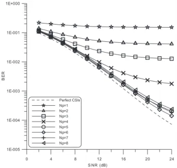
0 4 8 12 16 20 24 S NR (dB) 1E-005 1E-004 1E-003 1E-002 1E-001 1E+000 BE R Perfect CSIs Np=1 Np=2 Np=3 Np=4 Np=5 Np=6 Np=7 Np=8
Fig. 5. Bit error rate of CC pilot based STBC/OFDM system in a UMTS system defined fading channel with Npas a parameter (V = 120 km/hr).
A. The Performance of the System in a Two Path Fading Channel
Fig. 4 shows the bit error rate (BER) performance of the proposed system in a two-path fading channel with a relative path power profile: 0, 0 (dB) at different vehicle speeds. Here, we set the number of selected paths Np = 2. The system
performance is approximately only 1dB poorer (in SNR) at a BER=10−3as compared with the theoretic BPSK case with a
second-order diversity, even when the motor vehicle moves at a high speed. The simulated performance curves under the perfect CSIs assumption are also included for comparison purpose. These curves indicate that CC pilot-based channel estimation method works very well.
B. Path Selection Effects
Fig. 5 shows the BER performance of the proposed sys-tem in a UMTS defined multipath fading channel (with six paths) at a vehicle speed of 120 km/hr, with Np is chosen
as a simulation parameter. It is observed that the system performance have a small degradation of about 2dB at a BER=10−3 as compared with the previous two-path fading
channel case as shown in Fig.4. When the parameter Np is
chosen appropriately, i.e. close to the actual number of paths in the mobile radio environment, the system performance is almost the same. In other words, the parameter Np can be
set a little bit larger than the number of available paths in a practical system design.
VI. CONCLUSION
In this work, we designed a pilot signal structure for a STBC/OFDM system by utilizing a pair of complementary codes, which can be systematically generated from well-understood rules. We have also described the detailed func-tional block diagrams of the CC pilot-based STBC/OFDM system and simulated its performance. The CC pilot signals are transmitted simultaneously along with data signals in the time domain and used to estimate CSIs optimally at the receiver end. This approach does not reduce bandwidth efficiency as compared with other schemes in which pilot carriers are added in the frequency domain.
REFERENCES
[1] S. M. Alamouti, “A simple transmit diversity technique for wireless communications,” IEEE J. Select. Areas Commun., vol. 16, no. 8, pp. 1451-1458, Oct. 1998.
[2] V. Tarokh, H. Jafarkhani, and A. R. Calderbank, “Space-time block codes from orthogonal designs,” IEEE Trans. Inform. Theory, vol. 45, no. 5, pp. 1456-1467, July 1999.
[3] K. F. Lee and D. B. Williams, “A space-time coded transmitter diversity technique for frequency selective fading channels,” in Proc. IEEE
Workshop on Sensor Array and Multichannel Signal Processing, Mar.
2000, pp. 149-152.
[4] P. Garg, R. K. Mallik, and H. A. Gupta, “Performance analysis of space-time coding with imperfect channel estimation,” in Proc. IEEE Int. Conf.
Personal Wireless Comm., ICPWC, 2002, Dec. 2002, pp. 71-75.
[5] S.-A. Yang and J. Wu, “Optimal binary training sequence design for multiple-antenna systems over dispersive fading channels,” IEEE Trans.
Veh. Technol., vol. 51, no. 5, pp. 1271-1276, Sept. 2002.
[6] X. Ma, L. Yang, and G. B. Giannakis, “Optimal training for MIMO frequency-selective fading channels,” in 36th Asilomar Conf. Signals,
Systems, Comput., vol. 2, Nov. 2002, pp. 1107-1111.
[7] C. Fragouli, N. Al-Dhahir, and W. Turin, “Training-based channel estimation for multiple-antenna broadband transmissions,” IEEE Trans.
Wireless Commun., vol. 2, no. 2, pp. 384-391, Mar. 2003.
[8] G. Kang, E. Costa, M. Weckerle, and E. Schulz, “Optimum channel estimation over frequency-selective fading channel in multiple antenna systems,” in Proc. IEEE Int. Conf. Commun. Technology, ICCT, 2003, vol. 2, Apr. 2003, pp. 1799-1803.
[9] Y. Li, N. Seshadri, and S. Ariyavisitakul, “Channel estimation for OFDM systems with transmitter diversity in mobile wireless channels,”
IEEE J. Select. Areas Commun., vol. 17, no. 3, pp. 461-470, Mar. 1999.
[10] Y. Li, “Simplified channel estimation for OFDM systems with multiple transmit antennas,” IEEE Trans. Wireless Commun., vol. 1, no. 1, pp. 67-75, Jan. 2002.
[11] H. Minn, D. I. Kim, and V. K. Bhargava, “A reduced complexity channel estimation for OFDM systems with transmit diversity in mobile wireless channels,” IEEE Trans. Commun., vol. 50, no. 5, pp. 799-807, May 2002. [12] S. K. and J. S. Lehnert, “Channel estimation for OFDM systems with transmitter diversity for a quasi-static fading channel,” in Proc. IEEE
Military Commun. Conf., MILCOM, 2003, vol. 1, Oct. 2003, pp.
309-313.
[13] M. Golay, “Complementary series,” IEEE Trans. Inform. Theory, vol. 7, no. 2, pp. 82-87, Apr. 1961.
[14] R. Van Nee, “OFDM codes for peak-to-average power reduction and error correction,” in Proc. IEEE GLOBECOM’96, vol. 1, Nov. 1996, pp. 740-744.
[15] W. C. Jakes, Microwave Mobile Communications. New York: Wiley, 1974.
[16] J. Laiho, A. Wacker, and T. Novosad, Radio Network Planning and