I INTRODUCTION
Surface plasmon resonance (SPR) is a robust technology that has been a useful technique for obtaining quantitative or real time kinetic information on bioaffinity interactions [1-2]. Recent studies have shown that ellipsometric measurement in total internal reflection mode is also a useful method for observing the SPR phenomenon, and it has also been shown that ellipsometric parameters provide rich information about the sample under investigation [3]. Since the variations in both intensity and phase caused by changes in the resonance conditions of the surface plasmon wave can be analyzed simultaneously, the ellipsometric measurement was with the capability of increasing the dynamic range and improving the sensitivity under SPR condition [4]. In practical applications, the conditions of plasmon excitation are sensitive to the refractive index of the two contacting media; therefore, the shift of the resonance angle is used for studying biological binding events [5]. Except for the angular scan approach used to recording the shift of the resonance angle, the focus beam arrangement was an idea that provided more than one angle of incidence and allowed the whole SPR curve to be recorded without rotating the optical element. However, the focus beam approach was only valid for intensity measurement so far, and most phase shift measurements were based on the interferometry which was unable to be investigated by means of this approach.
In this work, we present a focus beam measurement technique that determines the phase and amplitude response under the surface plasmon resonance conditions. The angular convergence of incident beam was introduced by insertion of a cylindrical lens before the SPR sensor chip. Since the phase and amplitude were varied against the different incident angles of the converged incident beam, those variations can be determined through use of the imaging ellipsometric
Developing a Phase and Intensity Measurement Technique with
Multiple Incident Angles under Surface Plasmon Resonance
Condition
Chien-Yuan Han*, and Du Cheng You
Department of Electro-Optical Engineering, National United University, Maoli, Taiwan, R.O.C.
Yi-Ren Chen, and Yu-Faye Chao
Department of Photonics & Institute of Electro-Optical Engineering, National Chiao Tung
University, Hsinchu, Taiwan, R.O.C.
ABSTRACT
This work presents the application of a focused beam polarizer-sample-analyzer imaging ellipsometer in measuring the ellipsometric parameters under the surface plasmon resonance condition. By using a cylindrical lens to produce fan shaped beam with multiple incident angles, three-intensity measurement technique can measure the ellipsometric parameters against each incidence but without the need of calibrating the azimuth errors of polarizer and analyzer. As a result of multiple incident angles approach, the whole SPR curve can be obtained without rotating the sensor chip. The intensity and phase response in the air and water interface of the sensor chip were demonstrated, and almost all measured results are close to the theoretical model.
[Keywords] focused beam, ellipsometry, surface plasmon resonance,.
International Symposium on Photoelectronic Detection and Imaging 2013: Laser Sensing and Imaging and Applications, edited by Farzin Amzajerdian, Astrid Aksnes, Weibiao Chen, Chunqing Gao, Yongchao Zheng, Cheng Wang,
Proc. of SPIE Vol. 8905, 89052N · © 2013 SPIE · CCC code: 0277-786X/13/$18 · doi: 10.1117/12.2035029 Proc. of SPIE Vol. 8905 89052N-1
measurement approach. The key feature of this ellipsometric measurement development is that the phase and intensity shift, due to the non-ideal incidence of the focused beam, can be analytically corrected. Therefore, the ellipsometric parameters with whole SPR curve under the air and liquid circumstances were demonstrated in this article.
II THEORY
The most common technique for measurement of refraction indices or layer thickness is ellipsometry, which measures the change of polarization states of light reflected from the sample surface. A PSA imaging ellipsometer is illustrated in Fig. 1, where the light beam undergoes total internal reflection from a glass prism in contact with a gold spot to excite surface plasmons with photons of a particular frequency arriving at a specified incident angle. Reflection causes separate changes in the amplitude and phase of the p and s components of the reflected light field due to local changes in refractive index. The changes are usually characterized by the ratio of complex Fresnel reflection coefficient ρ, which can be expressed in terms of the ellipsometric parameters Ψ and Δ as:
tan p i s r e r ρ= = Ψ (1) Δ
Where rp and rs are the reflection coefficients of linearly polarized light parallel or perpendicular to the incident plane, respectively. The measured intensity can be written as
2 2 2 2 2
(sin sin tan cos cos 0.5tan cos sin2 sin2 ) o
I I= P A+ Ψ P A+ Ψ Δ P A (2) Where azimuths P and A are the transmission axes of the polarizer and the analyzer. When P=45°, the reflected intensity takes on an elliptical distribution [7] which can be formulated as
) ( sin 2 ) ( cos 2 ) (A = L 2 A−γ +T 2 A−γ I (3) Where L and T are the magnitudes of the maximum and the minimum intensities, respectively, and γ is the azimuth orientation of maximum intensity.
By comparing Eqs. (2) and (3), one can derive the following:
cos sin 2 sin 2 tan 2 cos 2 cos 2 P P
γ
= Δ Ψ − Ψ (4) − 2sin2(2 )=cot2Δ 4 ) ( γ LT T L (5) Equation (3) can also be simplified to:) 2 sin 2 cos 1 ( ) (A B C A D A I = + + (6) Where parameters B, C, and D can be written in terms of L, T, and γ:
B=0.5(L+T)
C=(L-T) cos2γ/(L+T) and
D=(L-T)sin2γ/(L+T).
It is easy to prove that parameters B, C, and D can be determined by measuring the intensities at A=0°,60°, and 120°:
) 120 ( ) 60 ( )] 120 ( ) 60 ( [ 1 2 )] 120 ( ) 60 ( ) 0 ( [ 3 1 ° ° ° ° ° ° ° − = + − = + + = I I D I I B C I I I B (7)
Proc. of SPIE Vol. 8905 89052N-2
from which one can obtain γ, L and T: L B T B DB L C D − = + = = 2 , 2 sin , 2 tan γ γ (8)
Rewriting Eq. (2) in terms of cos 2A and sin2A and comparing the result with Eq. (6), one can also show that
2 1 2 tan tan 1 C P C + Ψ = − (9)
Since P and A can be calibrated with a flat surface such as water, one can obtain the ellipsometric parameters of a flat surface with the 3I technique. It has been demonstrated that the azimuth deviation, α, of the polarizer can be obtained with the same measurement. Assuming the sensor chip deviates from the normal inclination of the incident plane by α, one can easily prove the following:
2 1 1 2 2 2 (1 )(1 sin 2 ) 45 tan (1 )(1 sin 2 ) (1 )(1 sin 2 ) 45 tan (1 )(1 sin 2 ) C P C C P C α α α α ° ° + + = + Ψ = − − + + = − Ψ = − − (10)
Where C1 and C2 are the corresponding parameters measured at P=+45° and P=- 45°, respectively. Ψ and α can be deduced by use of the 3I technique from the following relationships:
) 1 )( 1 ( ) 1 )( 1 ( 1 ) 1 )( 1 ( ) 1 )( 1 ( 1 2 sin 2 1 2 1 2 1 2 1 C C C C C C C C + − − + + + − − + − = α (11) 1 1 2 4 1 2 (1 )(1 ) tan [ ] (1 )(1 ) C C C C + − Ψ = − + (12) The value of Ψ thus obtained is independent of α and so provides the capability to measure the ellipsometric parameter on a curved surface. It is easy to prove that tan2γ1=- tan2γ2 from Eq. (4), where γ1 and γ2 are the azimuth orientations of the maximum intensity measured at P=+45° and P=- 45°, respectively.
Deviation of the analyzer can be computed by
) tan (tan 4 1 2 2 1 1 1 1 C D C D − − − = γ (13)
Instead of using a regression technique, we have developed an analytical solution approach to obtain the ellipsometric parameters Ψ and Δ which is free from the deviation of the polarizer and analyzer by measuring the intensities at both positive and negative polarizing angle at A=0°,60°, and 120° [6]. Three specific analyzer angles were set because the numerical calculations show that azimuthal angles of the analyzer differing from each other by 60o in this configuration is about 3 times less experimental random noise than differing from each other by 45o (i.e. 0°, 45°, and 90°) [7], and the deviation α also can be determined by taking the same measurements. Since P and A can be calibrated with a flat surface such as water, the measured α suspected to be equal to characterize the deviation of the incident beam respect to ideal incident plane.
Proc. of SPIE Vol. 8905 89052N-3
Laser
Beam Expander
Cylindrical lens SPR cell
Ground glass CCD
Polarizer Analyzer
II EXPERIMENT
In this experimental setup, the laser (Melles Griot 05-STP-901, λ=632.8nm, He-Ne laser) was expanded by a 7x beam expander and passed through a polarizer with azimuth angle at ±45°. The expanded beam was then focused by a cylindrical lens that covered a range of incident angles. After that, the light beam passed through the SPR sensor chip with the Kretschmann’s configuration. Since the light beam covered a range of angles, the incidents were set around the resonance angle during the measurement (i.e. 44° and 70°). The analyzer was mounted on a motor controlled rotator and three radiances were obtained with the analyzer azimuth at 0°, 60°, and 120°, respectively. After the beam propagated through the ground glass, the intensity was recorded by a CCD camera (Pike F-032, AVT). The system can determine the light reflected from the ideal incident pane where the α suspected to be zero; therefore, the ellipsometric parameters Ψ, Δ against different incident angles can be analyzed at the same time.
III RESULTS AND DISCUSSIONS
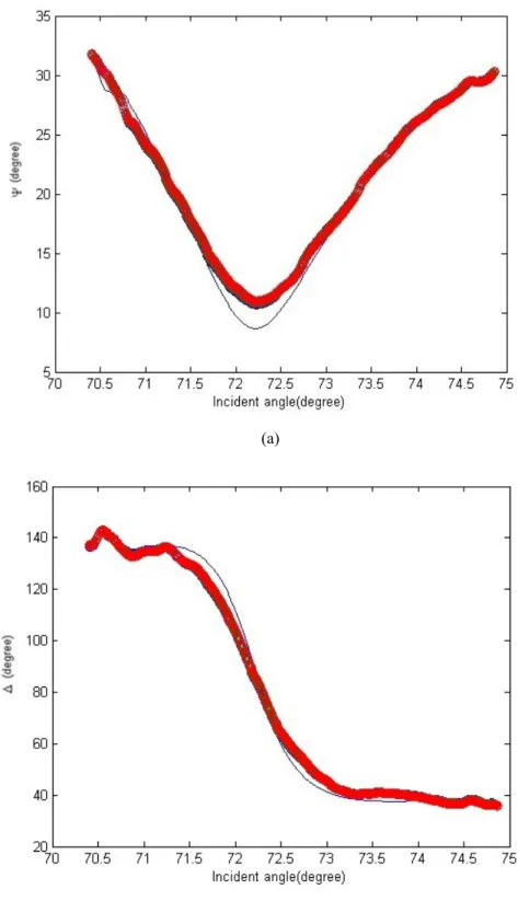
The merit of this measurement technique was that we were able to obtain all of the intensity and phase responses near the resonance. At the beginning, we set the incidence around 44° to examine the ellipsometric parameters Ψ and Δ while the sensor chip in air and Fig. 2 shows the experimental and theoretical results. The solid lines were the theoretical values, and the open circles were the measured values. Although the angle of the measured intensity dip was almost the same as the theoretical one, the magnitude of Ψ was slightly different before the resonance angle. Since the phase shift was much more sensitive than the intensity variation, the more difference in Δ further from the resonance angle also can be observed in Fig. 2(b). The reason measured Ψ and Δ is a little deviated from the theoretical value before resonance because each pixel corresponding to a unique incident angle may not be well calibrated. We also demonstrate the measurement results while the sensor chip is in Au/H2O assembly, as shown in Fig. 3. Since the SPR response curves were smooth in Au/H2O conditions, the theoretical and measured ellipsometric parameters, Ψ and Δ were very close. Some deviation in Ψ was present and has to be analyzed further.
Fig. 1 Experimental setup
Proc. of SPIE Vol. 8905 89052N-4
35 30 25 d d 20 15 10 43.6 43.8 44 44.2 Incident angle(degree) 44.4 44.6 44.8 44 44.1 44.2 44.3 Incident angle(degree) 44.4 44.5 44.6 (a) (b)
Fig. 2 Ellipsometric parameters versus incident angle while the sensor chip in air (a) Ψ distributions versus incident angle (2) Δ distributions versus incident angle (red circle: measured value, blue line: theoretical value)
Proc. of SPIE Vol. 8905 89052N-5
35 30 25 ?. 20 15 10 5 70 70.5 71 71.5 72 72.5 73 73.5 74 74.5 Incident angle(degree) 10O 140 120
'
1OO GO 400
05
71 71.5 72 72.5 73 73.5 |ucidemmng|o(degree) 74 74.5 75 (a) (b)Fig. 3 Ellipsometric parameters versus incident angle while the sensor chip in water: (a) Ψ distributions versus incident angle, (2) Δ distributions versus incident angle (red circle: measured value, blue line: theoretical value)
Proc. of SPIE Vol. 8905 89052N-6
IV CONCLUSIONS
In this work, we successfully demonstrate amplitude and phase responses under surface plasmon resonance conditions by use of a focused beam ellipsometry. The results show the variation trends between measured curves and theoretical ones were similar, and are useful to those who need multiple incident angles in their work. However, further studies in calibration procedures have to be carried out in the near future to identify the sample's exact properties, like refractive index or concentration.
REFERENCES
[1] N. Aldred, T. Ekblad, O. Andersson, B. Liedberg, A. S. Clare, ACS. Appl. Mater. Interfaces 3 2085 (2011) [2] C. Y. Han, Y. F. Chao, Sens. Actuators B 121 490 (2006).
[3]Y. H. Huang, H. P. Ho, S. Y. Wu, S. K. Kong, J. Adv. 12 Opt. 2012 (2012). [4] A.V. Kabashin, S. Patskovsky, A. N. Grigorenko, Opt. Express 17 21191. (2009)
[5] R. S. Moirangthem, Y. C. Chang, S. H. Hsu, P. K. Wei, Biosens. Bioelectron. 25 2633 (2010). [6] Y. F. Chao, K.Y. Lee, Y. D. Lin, Appl. Opt. 45 (2006) 3935.
[7] D. S. Sabatke, M. R. Descour, E. L. Dereniak, W. C. Sweatt, S. A. Kemme, G. S. Phipps, Opt. Lett. 25 (2000) 802.
Proc. of SPIE Vol. 8905 89052N-7