This content has been downloaded from IOPscience. Please scroll down to see the full text.
Download details:
IP Address: 140.113.38.11
This content was downloaded on 28/04/2014 at 21:29
Please note that terms and conditions apply.
Attosecond pulse synthesis and arbitrary waveform generation with cascaded harmonics of an
injection-seeded high-power Q-switched Nd:YAG laser
View the table of contents for this issue, or go to the journal homepage for more 2012 Laser Phys. Lett. 9 212
Abstract: We propose a new scheme of attosecond pulse gen-eration by starting from a narrow-band transform-limited high-power solid-state laser and phase lock the fundamental and its first four cascaded harmonics generated by the second-order nonlinear optical processes. The relative phase among the opti-cal fields of the harmonics can be maintained a constant at least for thousands of nanosecond pulses. The worst-case relative phase fluctuation is 0.04π rad. It is shown that sub-single-cycle (∼ 0.37 cycle) sub-femtosecond (360 attosecond) pulses with carrier-envelope phase (CEP) control can be generated in this manner. The peak intensity of each pulse exceeds 1014W/cm2 when it is focused to a spot size of 20 µm. We also demonstrate synthesis of square and saw-tooth waveforms.
Correl ation si gnal, a.u. 1 2 3 0 2 4 6 8 Time delay, fs CEP=0 4 2 0 -2 -4 1 0 -1
The electric field synthesized waveform retrieving by the method of shaper-assistant linear cross-correlation at CEP = 0. The inset figures show the simulation of electric field waveform in black solid line and pulse envelope in blue dash line
c
° 2012 by Astro Ltd.
Published exclusively by WILEY-VCH Verlag GmbH & Co. KGaA
Attosecond pulse synthesis and arbitrary waveform
generation with cascaded harmonics of an injection-seeded
high-power Q-switched Nd:YAG laser
W.-J. Chen,1,∗H.-Z. Wang,1R.-Y. Lin,2C.-K. Lee,3and C.-L. Pan1,4,5,∗ 1Department of Physics, National Tsing Hua University, Hsinchu 30013, Taiwan 2Department of Photonics, National Chiao Tung University, Hsinchu 30010, Taiwan 3Department of Photonics, National Sun Yat-Sen University, Kaohsiung 80424, Taiwan 4Institute of Photonics Technology, National Tsing Hua University, Hsinchu 30013, Taiwan
5Frontier Research Center on Fundamental and Applied Sciences of Matters, National Tsing Hua University, Hsinchu 30013, Taiwan
Received: 12 October 2011, Revised: 21 October 2011, Accepted: 24 October 2011 Published online: 16 January 2012
Key words: sub-cycle; attosecond; harmonic; carrier envelope phase; waveform
1. Introduction
Ultrashort pulses with attosecond scale resolution are nec-essary for probing the evolution of electronic processes in atoms, molecules, and condensed matter. The bandwidth of an attosecond pulse is more than few eV is required.
Besides, it is desirable to control the pulse shape in order to achieve coherent control of electronic motion in matter with light. This means that the amplitude and phase of the pulse must be controllable [1]. To date, several approaches are shown to be able to generate such a broadband spec-trum. High-order harmonic generation (HHG) is widely
Laser Phys. Lett. 9, No. 3 (2012) 213
used to generate attosecond pulse in extended ultraviolet (XUV) region [2]. In the optical region, the spectrum of the pulse must be expanded to span more than one oc-tave. An approach is to expand the spectrum of a mode-locked Ti:Sapphire laser directly [3]. Another approach is to link and phase-lock the spectra of two mode-locked lasers [4]. Self-channeling process can be used to gener-ate a supercontinuum spectrum by an intense few-cycle femtosecond pulse [5]. The other generic approach is the synthesis of multiple stokes and anti-stokes generated by the high-order stimulated Raman scattering (HSRS) pro-cess [6–11]. The first three aforementioned approaches are based on femtosecond laser systems. The techniques they used are sophisticated and the bandwidth just reaches one octave. The HSRS approach is based on single frequency nanosecond laser system. The bandwidth can exceed two octaves easily. It can be used for ultrafast waveform syn-thesis, but the synthesized pulse energy is low, around hun-dreds of µJ [12]. Strong field laser-matter interaction is es-sentially a sub-cycle phenomenon, which is illustrated by the processes of high-order harmonic generation [13–17]. For study of sub-cycle nonlinear optics [18], the pulse en-ergy is critical and must reach hundreds of mJ. Further, it is desirable to manipulate the amplitude and phase of such pulses. For example, the F. Krausz group demon-strated efficient XUV generation through waveform con-trol by sub-1.5-cycle pulse driving noble gas in 2008 [19]. In addition, the L.E. Chipperfield group proposed and esti-mated maximum electron recollision energy reachable by specific waveform of the single-cycle pulse in 2009 [20]. Therefore, a new light source with characteristics of high intensity, bandwidth exceeding two octaves and waveform control is necessary.
In this paper, we propose and demonstrate a new com-pact and stable coherent light source with bandwidth span-ning two octaves. The output pulse energy can reach hun-dreds of mJ. It is based on a high-energy, single-frequency, Q-switched Nd:YAG laser, which is a widely used in many scientific endeavors [21–25]. The idea is using the comb consisting of the fundamental (λ = 1064 nm) and harmon-ics of such a high power laser. The second through fifth harmonics are generated in cascade by phase-matched second-harmonic and sum-frequency generation in nonlin-ear optical crystals. The commensurate condition is satis-fied automatically for such a frequency comb, which can be used for synthesis of an attosecond pulse train with sta-ble carrier-envelope phase (CEP) [26,27]. The pulse en-ergy can reach Joule level, while the intensity can exceed at least 1013 W/cm2 when the coherent beam is focused
into a spot size of 20 µm. By modulating the amplitude and phase of each component of the frequency comb in-dependently, we can control the electric field waveform of synthesized pulse. Our approach makes it possible to set the periodic optical waveform in femtosecond to sub-femtosecond domain to be used in novel applications such as sub-femtosecond pump-probe and control [28], and sub-single-cycle nonlinear optics in the optical region.
2. Basic principles of waveform synthesis
We shall describe the working principle of our approach for waveform synthesis. When a frequency comb is phased for Fourier synthesis of a periodic waveform, the fre-quency ωi and the phase ϕi of the ith component of the comb are related byωi= ωceo+ iωn, ϕi = ϕ0i+ iϕn, (1) Where ωceois the carrier-envelope-offset frequency, ωnis the frequency spacing of the comb, ϕ0
i is the static off-set, and ϕn is the linear phase difference between adja-cent comb components. When the frequency comb com-ponents are commensurate, ωceovanishes [27]. In the case of a harmonic-generated comb, ωn is the fundamental frequency ω1. The harmonic frequencies ωi are obtained
by phase-matched harmonic generation from ω1with the
relation of ωi= iω1. The phase of each harmonic
fre-quency component satisfies the phase-matching condition
ϕi= ϕj+ ϕk+ π/2, where i = j + k. When the harmonics propagated for a distance in the air and pass through some optical devices, the relative phase (ϕi–ϕj) between har-monics is changed by the dispersion, but the value of rela-tive phase shift is kept constant. For waveform control, we need to find the value of relative phase shift and compen-sate it. In Eq. (1), the value of ϕnaffects the time delay of pulse train and will not change the electric field waveform. The time delay is (iϕn/ωi) = (ϕn/ω1). This is the degree of freedom for relative phase adjustment. In this work, we select the component ω5as the reference frame of relative
phase. By setting ϕ5= 0, we can get ϕn= – ϕ05/5, which is
used to determine the phase shift, ϕi= iϕn, of other fre-quency components. In this manner, we induces a same time shift of –ϕ0
5/5ω1for these frequency components, the
waveform is maintained. This scheme has another advan-tage: we only need four phase modulators instead of five.
3. Experimental setup
We performed a set of experiments to demonstrate wave-form synthesis by the harmonic frequency comb. The ex-perimental setup is shown in Fig. 1. The fundamental fre-quency component at ω1 is from a Quanta Ray
PRO-290 Q-switched Nd:YAG laser (λ = 1064 nm) operating at 10 Hz. The pulse duration is about 10 ns and the laser was injection-seeded such that its frequency bandwidth is narrower than 0.003 cm−1. The nonlinear optical crystals in harmonic generator are arranged in a cascaded layout. The crystals are KD*P type II for the second harmonic ω2,
KD*P type I for the third harmonic ω3, BaB2O4 (BBO)
type I for the forth harmonic ω4, and BBO type I for
the fifth harmonic ω5. Thus the spectra of the five
fre-quency components ranges from the near infrared (NIR) or 1064 nm to the ultraviolet (UV), i.e., 213 nm. The cascade
Quantum Ray Pro-290 HG AM PM WP P PP BBO PBP P PD a c b d
Figure 1 (online color at www.lphys.org) Experimental setup. HG – harmonic generator, AM – amplitude modulator, PM – phase modulator, WP – wave-plate, P – polarizer, PP – prism pair, BBO – BBO nonlinear optical crystal, PBP – Pellin-Broca prism, and PD – photodiode. The harmonic frequencies generated by harmonic generator, which includes four nonlinear optical crystals for SHG, THG, FHG, and 5HG, respectively. Amplitude modulator consists of half wave-plate and polarizer. Phase modulator consists of a pair of prism. The BBO crystals (a-d) are used to survey the relative phase between these harmonic frequencies. The heterodyne signal is measured by the photodiode
setup was adopted to ensure that the second-order nonlin-ear optical process all occurred collinnonlin-early so that funda-mental and harmonics overlapped spatially. The pulse en-ergy of each harmonic frequency is 380, 178, 70, 41, and 22 mJ. The polarizations of each frequency are elliptic, horizontal, vertical, vertical, and horizontal for ω1, ω2, ω3, ω4, and ω5, respectively. All the polarizations of harmonic
frequencies will be tuned into the horizontal polarization by using polarization components.
For adjusting the amplitude and the phase of each frequency components independently, we spatially dis-persed these harmonic frequencies by a fused silica prism then recollimate them into parallel but spatially separated beams by using another, larger prism. In the parallel co-propagating region, we inserted an amplitude modulator and a phase modulator each for each harmonics to adjust the amplitude and relative phase of these harmonics sep-arately. Each amplitude modulator is consisted of a half wave-plate and a polarizer. The polarization directions of the harmonic frequencies were all horizontal after passing through the polarizers. We can adjust the pulse energy of each harmonic by rotating the orientation of the half wave-plate. To deal with the elliptical polarization of the funda-mental frequency, we used a quarter wave-plate to rotate the elliptical polarization back to the linear polarization. The phase modulator is made by a pair of right-angle tri-angle prisms. Sliding the relative positions of the prisms along the hypotenuse will change the effective path length traveled by each harmonic. This scheme allows variation of the phase ∆ϕi, but will not affect the beam alignment. The phase will be altered by ∆ϕi= 2π(nprism– nair)l/λi, where l is the distance of sliding. Finally, these five beams of harmonic frequencies will be recombined and colli-mated by another prism set at a symmetry position to the first prism set. The whole setup is similar to a 4-f system.
4. Control of the relative phase among the
harmonics
By the Fourier’s theorem, any waveform can be formed by a series of cosine or sine waves with suitable combination of amplitudes and phases. It is straightforward to vary the amplitude of a particular harmonic by reorientate the half wave-plate in the amplitude modulator. For waveform con-trol, we just need to determine the relative phase among the harmonics. As mentioned above, we set the fifth harmonic as the reference and adjust the relative phase of all other four harmonic frequencies to the reference.
Now we demonstrate experimentally the mutual phase coherence and the control of relative phase among all of the components of the harmonic frequency comb. Because the comb frequencies are integral multiples of the fun-damental frequency, every harmonic can be heterodyned with a signal at the same frequency derived by optically summing two lower harmonics in a nonlinear crystal. Then the resulting interference signal can be used to calibrate the phase modulator and to align the phases of the harmonic frequencies [12].
We employed a set of four type I BBO crys-tals which are cut at (a) θ = 22.9◦ and ϕ = 0◦ for 1064 nm + 1064 nm → 532 nm, (b) θ = 31.3◦ and ϕ = 0◦ for 1064 nm + 532 nm → 355 nm, (c) θ = 47.7◦and ϕ = 0◦ for 532 nm + 532 nm → 266 nm, and (d) θ = 51.2◦ and
ϕ = 0◦for 1064 nm + 266 nm → 213 nm, respectively. The Nd:YAG laser harmonic frequencies and summed frequen-cies generated from the BBO crystal are then dispersed by a Pellin-Broca prism and detected by a set of photodiodes. Since the polarization of the summed output is orthogonal to that of the harmonics, a polarizer is used to project the polarization of the two states onto a common axis to en-able and maximize the heterodyning signal. With five fre-quency components, four measurements are needed for de-termining of their relative phases. These BBO crystals are
Laser Phys. Lett. 9, No. 3 (2012) 215
Hytereodyne signal, a.u.
0.1 0.2 0.3 0.4 (a) 0 200 400 600 800 Scanning time, s I II III i ii
Hytereodyne signal, a.u.
2.0 4.0 6.0 8.0 (b) 0 200 400 600 Scanning time, s I II III i ii
Hytereodyne signal, a.u.
1.0 2.0 3.0 (c) 0 200 400 600 Scanning time, s I II III i ii
Hytereodyne signal, a.u.
0.5 1.0 1.5 (d) 0 200 400 600 Scanning time, s I II III i ii
Figure 2 (online color at www.lphys.org) Relative phase alignment. The heterodyne signal generated from BBO crystal: (a) 532 nm, (b) 355 nm, (c) 266 nm, and (d) 213 nm. The squares are experimental data and the red curve is the scanning setting curve. The scan process is separated into three parts: (I) the search of relative phase position shown as sinusoidal curve, (II) testing the stability of relative phase as a flat line, and (III) moving the relative phase to the in-phase condition. The inset figures show the position of relative phase. When the heterodyne signal stays at peak, there is a phase difference of π/2 shown by the inset figure (i). When we move the relative phase to the mid position, the harmonic frequencies will reach the in-phase condition shown by the inset figure (ii)
fixed on a linear stage and the moving direction is perpen-dicular to the beam propagation direction. In our setup, the phase resolution for the five harmonics is 0.005π, 0.01π, 0.015π, 0.021π, and 0.028π from ω1to ω5, respectively.
First, the BBO crystal (a) (see Fig. 1) is inserted. The cor-responding heterodyne signal (532 nm) is the first maxi-mized by rotating the polarizer and then recorded as the phase difference ϕ2– 2ϕ1– π/2 is scanned by translating
laterally one prism in the phase modulator for ω1using a
microstepper. The heterodyne signal is shown in Fig. 2a. During scanning of the relative phase, we accomplished the following: (I) Survey the relative phase between ϕ1and ϕ2. (II) Fixing relative phase at an arbitrary position for
hundreds seconds to check stability. (III) Continue scan-ning to set relative phase to the predetermined position.
The insets in Fig. 2 show relative positions of frequency components at ω1and ω2. Here we set the ω2wave as the
reference and move ω1with respect to the wave at ω2. The
difference of relative phase positions was set either at (i)
π/2 or (ii) 0, respectively, for this experiment. The BBO
crystal (b) is used in process (b). The heterodyne signal (355 nm) is recorded as the phase difference ϕ3– ϕ2– ϕ1– π/2 is scanned while the phase detuning of ω1and ω2by ϕ and 2ϕ for maintain the relative phase of ω1and ω2. The
result is shown in Fig. 2b. The procedure is repeated for the process of BBO crystals (c), the second harmonic genera-tion, and (d), sum-frequency generagenera-tion, corresponding to processes (a) and (b), respectively. The results of the scans are illustrated in Fig. 2c and Fig. 2d. As shown, the magni-tudes of heterodyne signal at the starting position of each
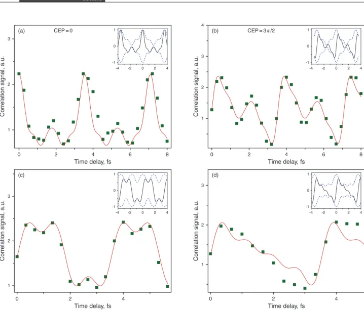
Correlation signal, a.u. 1 2 3 (a) 0 2 4 6 8 Time delay, fs CEP=0 4 2 0 -2 -4 1 0 -1 Correl ation si gnal, a.u. 1 2 3 4 (b) 0 2 4 6 8 Time delay, fs CEP=3π /2 4 2 0 -2 -4 1 0 -1 Correl ation si gnal, a.u. 1 2 3 (c) 0 2 4 Time delay, fs 4 2 0 -2 -4 1 0 -1 Correl ation si gnal, a.u. 1 2 3 (d) 0 2 4 Time delay, fs 4 2 0 -2 -4 1 0 -1
Figure 3 (online color at www.lphys.org) Electric field waveform. The electric field synthesized waveform retrieving by the method of shaper-assistant linear cross-correlation. (a) transform-limited cosine waveform at CEP = 0, (b) transform-limited sine waveform at CEP = 3π/2, (c) square waveform, and (d) sawtooth waveform. The inset figures show the simulation of electric field waveform in black solid line and pulse envelope in blue dash line
scan are different for each process. This indicates that, al-though the relative phases among the five beams are fixed, they are not matched at the input face position of the crys-tal. The mismatch originates from dispersions and shifts encountered during beam propagation. It is possible to set all the harmonic frequencies to be in-phase. This is shown in inset (ii) of Fig. 2d. This demonstrates our capability to set the relative phase and controlling the electromagnetic waveform.
This experiment demonstrates that the relative phase remains constant for thousands of nanosecond pulses and could be a lot much longer. The standard deviation of het-erodyne signal provides a measure of stability of relative phase. Amplitude fluctuations as well as relative phase fluctuations will contribute to the fluctuation in the hetero-dyne signal. If we conservatively attribute the fluctuations
as coming entirely from relative phase fluctuations, we see that the worst-case relative phase stability is 0.04π rad. In reality, the amplitude fluctuation of the harmonic fre-quency comb components from pulse to pulse is quite large (+/–10%). It is reasonable to conclude that the in-terpulse relative phase stability in the long term is a lot better than 0.04π.
5. Synthesis and retrieval of arbitrary
waveforms
Once the phases are aligned and the amplitudes are set to the values required for the desired waveform, the synthe-sis is complete. A train of pulses of a desired shape is
Laser Phys. Lett. 9, No. 3 (2012) 217
created from the superposition of these harmonics. The electric field of the pulses can be reconstructed from the known amplitudes and the alignment of the relative phases. For the optical waveform synthesis and measure-ment, the XUV attosecond pulse had been used to measure a few-cycle light waveform [29]. On the other hand, the shaper-assistant linear cross-correlation process had been used to retrieve the sub-cycle pulse waveform [12]. For the spectrum of our harmonic frequency comb is more than two octaves, the shortest pulses they can synthesize are transform-limited sub-cycle cosine pulses. We use the shaper-assistant linear cross-correlation process to retrieve the waveform.
After reaching the in-phase condition shown in Fig. 2d, we begin to retrieve the electric field of transform-limited cosine waveform. The detail of shaper-assistant linear cross-correlation process is described in reference [12]. After diverting part of the pulse energy to the probe, the energies of these five harmonic frequencies used to syn-thesize the cosine waveform are 120, 100, 6, 13, and 2 mJ per pulse, respectively. The normalized amplitudes of har-monics are {1, 0.91, 0.23, 0.33, 0.13}. Fig. 3a shows the sub-cycle transform-limited cosine waveform each span-ning 0.37 optical cycle with a temporal field full width at half maximum (FWHM) of 520 attoseconds. Adding the phases of all harmonic frequencies by 3π/2, the pulse envelope profile does not change, but the carrier electric field waveform will change to a sine function as shown in Fig. 3b. Fig. 3c shows the square waveform, which was synthesized by just three harmonic frequencies. The am-plitudes of the harmonics relative to that of the fundamen-tal for the three are {1,0,1/3}. Fig. 3d shows the sawtooth waveform that was synthesized by four harmonic frequen-cies. The corresponding amplitude ratio is {1,1/2,1/3,1/4}. These figures show that commonly used periodic wave-forms such as square and sawtooth can be synthesized closely resembling the real waveform with just a few har-monics. If we were using the optimized condition of full power distribution of five harmonics at 380, 178, 70, 41, and 22 mJ, the transform-limited cosine waveform will be a temporal FWHM of 480 attoseconds. The time duration of the intensity envelope is 700 attoseconds. The intensity of each attosecond pulse will exceed 1014W/cm2when it
is focused to a spot size of 20 µm. If the pulse energy of all the harmonics were the same, e.g., 22 mJ, the transform-limited cosine waveform will exhibit a temporal FWHM of 360 attoseconds and the time duration of the intensity en-velope would be 640 attoseconds. This should be the short-est pulse duration in the optical region so far, to the bshort-est of our knowledge. The intensity of per attosecond pulse still exceeds 1013W/cm2.
6. Conclusion
We propose and demonstrate a new scheme of attosecond pulse generation. Starting from a narrow-band
transform-limited high-power Q-switched Nd:YAG laser, we gen-erate the first four cascaded harmonics, 532 nm through 213 nm, which spatially overlap and co-propagate to the far fields. The spectral bandwidth of this coherent laser source thus exceeds two octaves or 32200 cm−1.The am-plitude and phase of the comb consisting of the five fre-quency components can be independently controlled. This made it possible to synthesize sub-single-cycle attosec-ond pulses. The repetition rate of the pulses in the pulse train is 241 THz, as determined by the fundamental fre-quency. The relative phase between the harmonics can be set to be a constant at least for thousands of nanosec-ond pulses. The worst-case relative phase stability is es-timated be 0.04π rad. It is shown that sub-single-cycle (∼ 0.37 cycle) sub-femtosecond (360 attosecond) pulses with carrier-envelope phase (CEP) control can be gener-ated in this manner. The peak intensity of each pulse ex-ceeds 1014 W/cm2 when it is focused to a spot size of
20 µm. We also demonstrate synthesis of square and saw-tooth waveforms.
Acknowledgements This work was supported by grants
spon-sored by the National Science Council of Taiwan (NSC 98-2112-M-009-015-MY3) and Phase II of the Academic Top University Program of the Ministry of Education, Taiwan.
References
[1] C.-B. Huang, Z. Jiang, D.E. Leaird, J. Caraquitena, and A.M. Weiner, Laser Photon. Rev. 2, 227 (2008).
[2] M. Hentschel, R. Kienberger, Ch. Spielmann, G.A. Reider, N. Milosevic, T. Brabec, P. Corkum, U. Heinzmann, M. Drescher, and F. Krausz, Nature 414, 509 (2001). [3] L. Matos, D. Kleppner, O. Kuzucu, T.R. Schibli, J. Kim,
E.P. Ippen, and F.X. Kaertner, Opt. Lett. 29, 1683 (2004). [4] R.K. Shelton, L.-S. Ma, H.C. Kapteyn, M.M. Murnane,
J.L. Hall, and J. Ye, Science 293, 1286 (2001).
[5] E. Goulielmakis, S. Koehler, B. Reiter, M. Schultze, A.J. Verhoef, E.E. Serebryannikov, A.M. Zheltikov, and F. Krausz, Opt. Lett. 33, 1407 (2008).
[6] S.E. Harris and A.V. Sokolov, Phys. Rev. Lett. 81, 2894 (1998).
[7] A.V. Sokolov, D.R. Walker, D.D. Yavuz, G.Y. Yin, and S.E. Harris, Phys. Rev. Lett. 85, 562 (2000).
[8] J.Q. Liang, M. Katsuragawa, F.L. Kien, and K. Hakuta, Phys. Rev. Lett. 85, 2474 (2000).
[9] S.W. Huang, W.-J. Chen, and A.H. Kung, Phys. Rev. A 74, 063825 (2006).
[10] T. Suzuki, M. Hirai, and M. Katsuragawa, Phys. Rev. Lett. 101, 243602 (2008).
[11] A.M. Burzo and A.V. Sokolov, Laser Phys. 19, 1677 (2009).
[12] H.-S. Chan, Z.-M. Hsieh, W.-H. Liang, A.H. Kung, C.-K. Lee, C.-J. Lai, R.-P. Pan, and L.-H. Peng, Science 331, 1165 (2011).
[13] F. Krausz and M. Ivanov, Rev. Mod. Phys. 81, 163 (2009). [14] I.A. Burenkov, A.M. Popov, O.V. Tikhonova, and E.A.
Volkova, Laser Phys. Lett. 7, 409 (2010).
[15] A.M. Popov, O.V. Tikhonova, and E.A. Volkova, Laser Phys. 21, 1593 (2011).
[16] M. Negro, C. Vozzi, K. Kovacs, C. Altucci, R. Velotta, F. Frassetto, L. Poletto, P. Villoresi, S. De Silvestri, V. Tosa, and S. Stagira, Laser Phys. Lett. 8, 875 (2011).
[17] C. Vozzi, F. Calegari, F. Frassetto, M. Negro, L. Poletto, G. Sansone, P. Villoresi, M. Nisoli, S. De Silvestri, and S. Stagira, Laser Phys. 20, 1019 (2010).
[18] J. Mauritsson, J.M. Dahlstr¨om, E. Mansten, and T. Fordell, J. Phys. B 42, 134003 (2009).
[19] E. Goulielmakis, M. Schultze, M. Hofstetter, V.S. Yakovlev, J. Gagnon, M. Uiberacker, A.L. Aquila, E.M. Gullikson, D.T. Attwood, R. Kienberger, F. Krausz, and U. Kleineberg, Science 320, 1614 (2008).
[20] L.E. Chipperfield, J.S. Robinson, J.W.G. Tisch, and J.P. Marangos, Phys. Rev. Lett. 102, 063003 (2009).
[21] J. ˇSulc, J. Nov´ak, H. Jel´ınkov´a, K. Nejezchleb, and V. ˇSkoda, Laser Phys. 20, 1288 (2010).
[22] J.W. Liu, C.Q. Gao, L. Wang, L. Zou, and J.Z. Li, Laser Phys. 20, 1886 (2010).
[23] J. Tauer, H. Kofler, and E. Wintner, Laser Phys. Lett. 7, 280 (2010).
[24] S.B. Zhang, Q.J. Cui, B. Xiong, L. Guo, W. Hou, X.C. Lin, and J.M. Li, Laser Phys. Lett. 7, 707 (2010).
[25] M. Jel´ınek, Jr. and V. Kubeˇcek, Laser Phys. Lett. 8, 657 (2011).
[26] W.-J. Chen, Z.-M. Hsieh, S.W. Huang, H.-Y. Su, C.-J. Lai, T.-T. Tang, C.-H. Lin, C.-K. Lee, R.-P. Pan, C.-L. Pan, and A.H. Kung, Phys. Rev. Lett. 100, 163906 (2008). [27] Z.-M. Hsieh, C.-J. Lai, H.-S. Chan, S.-Y. Wu, C.-K. Lee,
W.-J. Chen, C.-L. Pan, F.-G. Yee, and A.H. Kung, Phys. Rev. Lett. 102, 213902 (2009).
[28] T. Nakajima and S. Watanabe, Phys. Rev. Lett. 96, 213001 (2006).
[29] E. Goulielmakis, M. Uiberacker, R. Kienberger, A. Bal-tuska, V. Yakovlev, A. Scrinzi, Th. Westerwalbesloh, U. Kleineberg, U. Heinzmann, M. Drescher, and F. Krausz, Science 305, 1267 (2004).