Characterization and Design of Cylindrical
Microstrip Leaky-Wave Antennas
Lieh-Chuan Lin, Hayato Miyagawa, Toshihide Kitazawa, Senior Member, IEEE,
Ruey Bing Hwang, Senior Member, IEEE, and Yu-De Lin, Member, IEEE
Abstract—The spectral-domain approach is applied for the analysis and the design of the cylindrical microstrip leaky-wave antenna. The first higher-order leaky-mode is thoroughly investi-gated. We perform the well-known spectral-domain approach and Galerkin’s method to acquire the complex propagation constants of leaky modes, which are verified with results obtained by the scattering-parameter extraction technique. Two practical an-tennas are designed and implemented. Measured return loss and radiation patterns show a good performance of these cylindrical antennas, compared to that of the planar ones.
Index Terms—Cylindrical microstrip, leaky-wave, spectral-domain approach (SDA).
I. INTRODUCTION
S
PACE-WAVE leaky modes on many kinds of planar transmission lines have been widely studied and also re-ceived numerous attentions [1]–[6]. Leaky-wave antennas are well-known for their advantages such as high-gain, wide-band, etc. They also have the frequency-scanning feature. Although cylindrical transmission lines have been researched in [7]–[14], printed leaky-wave antennas based on cylindrical substrates have yet to be studied thoroughly in the literatures [15]–[17], which may find applications in systems that require conformal antennas in cylindrical shapes.This paper first presents an analysis to obtain the propaga-tion characteristics of the first higher order leaky mode on the cylindrical microstrip antennas. In Section II, we use the spec-tral domain approach (SDA) [18] to characterize the first higher order mode of the cylindrical microstrip line. Odd-symmetry and even-symmetry current basis functions are chosen in the longitudinal and transverse directions, combined with the edge conditions. Section III contains the numerical results that char-acterize the effects of different outer radii of cylinders, substrate thicknesses, and strip widths. The leaky-mode scattering param-eter extraction technique [19] is also used to provide a verifi-cation of the numerical results obtained by SDA. Section IV shows the implementation and measurements of two cylindrical leaky-wave antennas with aperture-coupling feeding structures. Both of these antennas have high gains and wide bandwidth.
Manuscript received December 8, 2006; revised January 25, 2008. Pub-lished July 7, 2008 (projected). This work was supported in part by the National Science Council under Grants NSC 95–2218-E-009–041 and NSC 95–2752-E-002–009, and in part by the Kinki Mobile Radio Center, Foundation under KMRC R&D Grant for Mobile Wireless.
L-.C. Lin, R. B. Hwang, and Y.-D. Lin are with National Chiao Tung Uni-versity, Hsinchu, Taiwan, R.O.C. (e-mail: [email protected]).
H. Miyagawa and T. Kitazawa are with Ritsumeikan University, Kusatsu, Shiga 525-8577, Japan.
Digital Object Identifier 10.1109/TAP.2008.924693
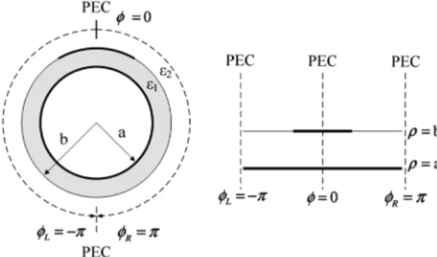
Fig. 1. The cross-sectional view of the cylindrical microstrip line.
II. THEORY
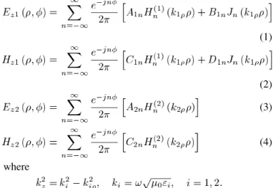
Fig. 1 shows the cross section of the cylindrical microstrip line. Region I is the cylindrical substrate with a permittivity of and a thickness of . Region II is free space. The strip with a circumferential width is placed on top of the sub-strate. And the inner ground conductor is located at a circumfer-ence of radius . The permeabilities of all materials are . The thickness of the strip and the ground conductor are assumed to be zeros. We expand the z-components of fields in cylindrical coordinates by inverse Fourier series (suppressing the time-har-monic expression and z-dependence ) [12] as
(1)
(2) (3)
(4) where
and define the -direction propagation constant such that , where and are the attenuation con-stant and the phase concon-stant, respectively. is the -directed
propagation constant. The can be expressed
in terms of from Maxwell’s equations in cylindrical coordinates.
To analyze the first higher order leaky mode with an odd symmetry, we place a PEC boundary at the bottom
Fig. 2. The PEC boundary representation and transformation.
in Fig. 2. The longitudinal fields between the PEC sidewalls are the standing waves, in the circumferential direc-tion as opposed to the creeping waves in [15]. In the structure under consideration in this paper, the propagation direction of the microstrip leaky-wave antenna is along the -direction of the cylinder. Should some applications demand that the propagation direction of the microstrip leaky-wave antennas be along the -direction of the cylinder, the analysis method in [15] that im-plemented Watson transform to take into account, the creeping waves, surface waves, and space-wave leaky waves should be employed.
The cross-section on the -plane can be transformed into that of the planar microstrip line with the PEC sidewalls, like shielded microstrip lines. This direct mapping is similar to that used in [20]. Since the two endpoints and
are actually the same points and at the same PEC boundary, the fields between them are periodic functions.
To compute the fields in the sidewalls, the variables of the inverse Fourier series (1)–(4) are integers on the real axis ( -axis) of the -plane. In solving planar microstrip leaky-wave structures [21]–[24], the variables used in integrations over the real axis are continuous; however, variables are discrete in solving cylindrical structures. Since the surface-wave leakage phenomenon in planar transmission lines will not occur in cylindrical substrates, no consideration of the surface wave leakage is needed in this analysis. The branch points in solving planar microstrip leaky-wave structures [21]–[24] are not needed in solving cylindrical structures because the variables are irrelevant to .
The sign of -direction wavenumber in free space in the series (1)–(4) should be chosen properly to sat-isfy the exponential growth condition of the space-wave leakage in the positive -direction, and this square root is at the improper Riemann sheet. The similar choice of branch is defined in [25]. Resorting to the orthogonality of the eigenfunction in di-rection, boundary conditions in spectral domain are used to de-termine the unknowns
On the ground conductor
(5) On the boundary between the substrate and the air
(6) (7)
are solved and we obtain the relationships between and (10) (11) The current densities , are expanded in terms of
basis functions , as
(12) with unknown coefficients . The basis functions used in the computations are
(13a)
(13b)
considering that z-component and -component currents are odd and even and functions of , respectively. The numbers of basis functions and , are and , respectively. Taking the inverse Fourier transform of (10)–(11), we can ob-tain the tangential field in Region II. Then we apply the re-maining boundary conditions that the tangential fields vanish on the strip
(14)
(15) For numerical computation, we take the inner product of the above equations with the basis functions and as testing functions (Galerkin’s method) over the strip
(17) where the asterisk stands for the complex conjugate, and the constant factor is omitted. The numbers of testing func-tions and , are and , respectively. Equation (16) and (17) can be rewritten in a matrix form
(18)
with , where and are the column vectors
of the unknown coefficients. The nontrivial solution of the com-plex propagation constant exists only if
(19)
III. NUMERICALRESULTS
Some numerical computations are carried out to investi-gate the propagation characteristics of cylindrical microstrip leaky-wave antennas. Convergences, comparisons with the leaky-mode scattering parameter extraction technique, and effects under different structural parameters are shown.
The structural parameters (Fig. 1) used in the following com-putation are: the strip width is 10 mm, the dielectric constant of the substrate is 2.2, the thickness of the substrate is 0.508 mm, and the outer radius is 10 mm.
A. Convergence Test
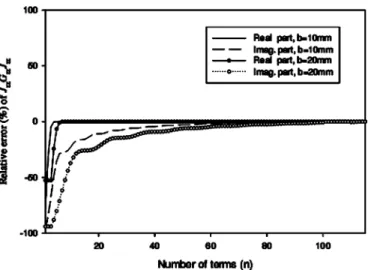
Each element of the Q-matrix is an infinite series, e.g.,
(20)
But it is impossible to have infinite terms in practical com-putations. Convergence of the infinite series is investigated to clarify the truncation error. We show the relative deviation (from case) of real and imaginary parts in Fig. 3 to check the convergence of the series. Smaller outer radius causes the series to converge a little bit faster. Good convergences are obtained with the number of the summation terms and with more than six basis functions used. The relative deviation of propaga-tion constants for the number of basis funcpropaga-tions is displayed in Fig. 4.
Fig. 3. Convergence of seriesJ G J . w = 10 mm, h = 0:508 mm, " = 2:2, and b = 10 and 20 mm at 9.5 GHz.
Fig. 4. Convergence of normalized phase constant and normalized attenuation constant of cylindrical microstrip leaky-wave antenna.w = 10 mm, h = 0:508 mm, " = 2:2, b = 10 and 20 mm at 9.5 GHz.
B. Comparison of the Results From the SDA to the Result From the Leaky-Mode Scattering Parameter Extraction Technique
To check the validity of the numerical results, we introduce the leaky-mode scattering parameter extraction technique [19] to extract the propagation constants from scattering parameters. In the technique, we choose two sections of leaky-wave mi-crostrip lines, with the same design except their longitudinal lengths. Then we place two identical leaky-mode excitation cir-cuits at the both ports of each of the two leaky-wave microstrip lines. After we obtain the two sets of scattering parameters of these leaky-wave microstrip lines from the full-wave simulation software, we can extract the propagation constants with some simple calculations based on the transmission line theory [26].
Numerical results obtained by this method are checked with those obtained by SDA. They show a good agreement. An ex-ample is presented in Fig. 5.
Fig. 5. Comparisons of propagation constants of the first higher order mode (w = 10 mm, h = 0:508 mm, " = 2:2, b = 30 mm).
Fig. 6. Normalized phase constants of the first higher order mode (w = 10 mm, h = 0:508 mm, " = 2:2, b = 10, 20, 30 mm and planar).
C. Effect of Different Outer Radii
First we use angular width of the line width to the outer radius of the substrate
(21) This definition represents the curvature of the cylindrical structure. If the radius becomes larger with a fixed line width, the angular width decreases, which indicates that the structure is flatter. For example, the substrate thickness is 0.508 mm and the antenna width is 10 mm. We choose three different outer radii, , 20, and 30 mm with three angular widths: 1, 0.5, and 1/3. It is reasonable that when the radius increases, the propagation constants gradually approach those of the planar microstrip leaky-wave modes.
Fig. 6 shows the computed normalized phase constant and Fig. 7 shows the computed normalized attenuation constants
, where . We find that as the outer radius or the angular width R becomes larger, the radiation region moves to a lower frequency band, with the point , which can be used as the lower frequency limit
Fig. 7. Normalized attenuation constants of the first higher order mode (w = 10 mm, h = 0:508 mm, " = 2:2, b = 10, 20, 30 mm and planar).
Fig. 8. Propagation constants of the first higher order mode (w = 10 mm, h = 0:508 and 1.570 mm, " = 2:2, b = 10 mm).
of effective space-wave leakage [3]. The lower frequency limit occur at about 9.65, 9.45, and 9.25 GHz, for , 20, and 30 mm, respectively.
D. Effect of Different Substrate Thicknesses
Fig. 8 plots the computed normalized attenuation constants and the normalized phase constants for two different substrate thicknesses and 1.570 mm, with the same outer radius . The antenna width is 10 mm. When the substrate is thicker, the radiation region moves to a lower frequency band. In planar microstrip leaky-wave antennas, sim-ilar effects can be observed [5]. The attenuation constant also becomes smaller, which means less attenuation. The lower frequency limit of effective space-wave leakage is 8.75 and 9.65 GHz for and 0.508 mm, respectively.
E. Effect of Different Line Widths
Fig. 9 shows the effects of the line width on the propaga-tion constants of the cylindrical microstrip leaky-wave antennas. From Fig. 9, a smaller microstrip line width results in a higher frequency band for space-wave leakage. In planar microstrip leaky-wave antennas, similar effects can be observed [1]. The
Fig. 9. Propagation constants of the first higher order mode (w = 9, 10, and 11 mm,h = 0:508 mm, " = 2:2, b = 30 mm).
lower frequency limits of effective space-wave leakage appear at about 8.55, 9.30, and 10.15 GHz, corresponding to widths
, 10, and 9 mm, with almost the same values
. As the line width reduces, the lower frequency limit of the effective space-wave leakage increases.
IV. ANTENNADESIGN ANDMEASUREMENTS
After computing the dependence of the propagation constants on structural parameters (line widths, substrate thicknesses and permittivities, etc.) from the theory above, we can determine the radiation regions of cylindrical microstrip leaky-wave antennas.
Next, we design aperture-coupling feeding structures with enough bandwidth to deliver power into antennas. Fig. 10 shows the configuration of the antenna system. The antenna system consists of two layers of substrates. The upper substrate is uti-lized for the antenna, and lower substrate is applied for the feeding microstrip line, respectively. Both substrates share the same ground with the coupling slot. The top view of the antenna system in Fig. 11 shows the positions of the coupling slot and the feeding microstrip line.
Both of these substrates have a dielectric constant
and a thickness of . Substrates thicker than 0.508 mm are too firm to bend into the cylindrical shape. The energy goes through the coupling slot to the leaky-wave mi-crostrip and excites the first higher leaky mode [4].
The dimensions used are the following: the feeding line width , the distance from the feed line end to the
an-tenna center , the slot width ,
the distance from the slot end toward the antenna to the
an-tenna starting point , the slot length with
, the antenna width , and the antenna length . These values are selected to obtain a good impedance matching. Two sets of antennas with
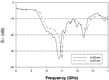
and 30 mm are designed, which are specified as Antenna I and Antenna II, respectively. From the measured scattering parame-ters shown in Fig. 12, the bandwidth (with reflection coefficient ) of Antenna I is 9.59–12.71 GHz; and that for
Fig. 10. The feeding and the antenna structure.
Fig. 11. The top view of feeding and the antenna structure.
Fig. 12. Measured reflection coefficient of the cylindrical microstrip antenna with two angular widths (w = 10 mm, h = 0:508 mm, " = 2:2, b = 20 and 30 mm).
Antenna II is 9.77–12.89 GHz. They both have 3.12 GHz band-width. It is noted that this kind of antenna has the potential to be a good wideband antenna.
From the results in Fig. 12, we can find that a larger radius causes a lower operating frequency. We select two different
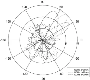
Fig. 13. Measured copolarization radiation patterns of the cylindrical mi-crostrip antenna with a outer radiusb = 20 mm.
Fig. 14. Measured copolarization radiation patterns of the cylindrical mi-crostrip antenna with an outer radiusb = 30 mm.
outer radii and 20 mm of antennas to measure their re-turn losses. There are two dips in near 11 GHz and 12.5 GHz for each cases ( for the solid line and for the dashed line). The dips are mainly due to the original resonant modes of the feeding micrsotrip lines, the feeding substrates, and the ground plane.
Copolarization radiation patterns of Antenna I and Antenna II in -plane are plotted in Figs. 13 and 14. Antenna I have the peak gains 11.79, 14.86, and 11.76 dBi for 10, 11, and 12 GHz, respectively, in Fig. 13.The corresponding mainbeam directions starting from the -direction (endfire direction) are 67 , 46 , and 33 . This is the well-known frequency-scanning feature of leaky-wave antennas.
TABLE II
MEASURED ANDCOMPUTEDMAINBEAMDIRECTIONS OFANTENNAII
With the same three frequencies selected above, Antenna II has 12.76, 14.82, and 11.96 dBi peak gains, as shown in Fig. 14. Compared to the Antenna I, larger outer radius of the antenna causes smaller mainbeam directions from the endfire, due to its larger phase constants. This phenomenon can be deduced from the data in Fig. 6.
For space-wave leaky modes, normalized phase constants and mainbeam directions from the endfire directions have the following theoretical relationship:
(22) Therefore, we compare our measured mainbeam directions with computed mainbeam directions from (22) in Tables I and II, for and 30 mm, respectively. Reasonable agree-ments are observed in both cases ( and 30 mm).
V. CONCLUSION
This paper proposes a cylindrical microstrip antenna struc-ture with a full-wave analysis and its implementation. Mea-sured scattering parameters and radiation patterns of these re-alized antennas circuits are presented. We investigate how the angular widths and the substrate thicknesses affect the propa-gation constants and radiation patterns of this cylindrical struc-ture. Finally, we conclude that cylindrical leaky-wave antennas have the high-gain and wideband features, similar to those of the planar leaky-wave antennas.
REFERENCES
[1] G.-J. Chou and C.-K. C. Tzuang, “An integrated quasi-planar leaky-wave antenna,” IEEE Trans. Antennas Propag., vol. 44, no. 8, pp. 1078–1085, Aug. 1996.
[2] Y.-D. Lin, J.-W. Sheen, and C.-K. C. Tzuang, “Analysis and design of feeding structures for microstrip leaky wave antenna,” IEEE Trans. Microw. Theory Tech., vol. 44, no. 9, pp. 1540–1547, Sep. 1996. [3] Y.-D. Lin and J.-W. Sheen, “Mode distinction and radiation efficiency
analysis of planar leaky-wave line source,” IEEE Trans. Microw. Theory Tech., vol. 45, no. 10, pp. 1672–1680, Oct. 1997.
[4] T.-L. Chen and Y.-D. Lin, “Aperture-coupled microstrip line leaky wave antenna with broadside mainbeam,” Electron. Lett., vol. 34, no. 14, pp. 1366–1367, Jul. 1998.
[5] T.-L. Chen, “Aperture-coupling excitation and mode-coupling phe-nomena of microstrip leaky modes,” Ph.D. dissertation, National Chiao Tung University, Hsinchu, Taiwan, R.O.C., 1999.
[6] W. Hong, T.-L. Chen, C.-Y. Chang, J.-W. Sheen, and Y.-D. Lin, “Broadband tapered microstrip leaky-wave antenna,” IEEE Trans. Antennas Propag., vol. 51, no. 8, pp. 1922–1928, Aug. 2003. [7] I. Jayakumar, R. Garg, B. Sarap, and B. Lal, “A conformal cylindrical
microstrip array for producing omnidirectional radiation pattern,” IEEE Trans. Antennas Propag., vol. 34, no. 10, pp. 1258–1261, Oct. 1986.
[8] K. Naishadham, “Spectral representation of the green’s functions for microstrip antennas on cylindrical substrates,” in Antennas and Prop-agation Society Int. Symp. Digest, 1998, pp. 1160–1164.
[9] K. Gu and Y. Wang, “Analysis of dispersion characteristics of cylin-drical microstrip line with method of lines,” Electron. Lett., vol. 26, no. 11, pp. 748–750, May 1990.
[10] F. Medina and M. Horno, “Spectral and variational analysis of gener-alized cylindrical and elliptical strip and microstrip lines,” IEEE Trans. Microw. Theory Tech., vol. 38, no. 9, pp. 1287–1293, Sep. 1990. [11] W. Y. Tam, A. K. Y. Lai, and K. M. Luk, “Full wave analysis of
aperture-coupled cylindrical rectangular microstrip antenna,” Electron. Lett., vol. 30, no. 18, pp. 1461–1462, Sep. 1994.
[12] K.-L. Wong, Design of Nonplanar Microstrip Antennas and Transmis-sion Lines. New York: Wiley, 1999.
[13] H. Yamamoto, H. Miyagawa, T. Nishikawa, K. Wakino, and T. Ki-tazawa, “Full-wave analysis for propagation characteristics of cylin-drical coplanar waveguides with finite thickness of conductor,” IEEE Trans. Microw. Theory Tech., vol. 53, no. 6, pp. 2187–2195, Jun. 2005. [14] T. M. Habashy, S. M. Ali, and J. A. Kong, “Input impedance and ra-diation pattern of cylindrical-rectangular and wraparound microstrip antennas,” IEEE Trans. Antennas Propag., vol. 38, pp. 722–731, May 1990.
[15] R. Paknys and D. R. Jackson, “The relation between creeping waves, leaky waves, and surface waves,” IEEE Trans. Antennas Propag., vol. 53, pp. 898–907, Mar. 2005.
[16] A. A. Mitkees, E. A. Abdallah, S. M. Hamdy, and A. A. Elsohly, “Char-acteristic features of leaky-wave microstrip antenna on cylindrical sur-faces,” in Proc. Asia-Pacific Microwave Conf., Aug. 1992, vol. 1, pp. 389–392.
[17] H. Miyagawa, T. Nishikawa, K. Wakino, W. Hong, Y.-D. Lin, and T. Kitazawa, “Space-wave leakage of strip lines on circular substrate,” in Proc. 36th European Microwave Conf., Sep. 2006, pp. 638–641. [18] T. Itoh, Ed., Numerical Techniques for Microwave and
Millimeter-Wave Passive Structure. New York: Wiley, 1989.
[19] J.-W. Sheen, Y.-D. Lin, and T.-L. Chen, “A leaky-mode S-parameter extraction technique for efficient design of the microstrip line leaky-wave antenna,” in 1999 IEEE MTT-S Int. Microleaky-wave Symp. Dig., vol. 1, pp. 175–178.
[20] L.-R. Zeng and Y. Wang, “Accurate solutions of elliptical and cylin-drical striplines and microstrip,” IEEE Trans. Microw. Theory Tech., vol. 34, no. 2, pp. 259–265, Feb. 1986.
[21] D. Nghiem, J. T. Williams, D. R. Jackson, and A. A. Oliner, “Existence of a leaky dominant mode on microstrip line with an isotropic substrate: Theory and measurements,” IEEE Trans. Microw. Theory Tech., vol. 44, no. 10, pp. 1710–1715, Oct. 1996.
[22] F. Mesa, C. di Nallo, and D. R. Jackson, “The theory of surface-wave and space-wave leaky-mode excitation on microstrip lines,” IEEE Trans. Microw. Theory Tech., vol. 47, no. 2, pp. 207–215, Feb. 1999. [23] F. Mesa, D. R. Jackson, and M. L. Freire, “Evolution of leaky modes
on printed-circuit lines,” IEEE Trans. Microw. Theory Tech., vol. 50, no. 1, pp. 94–104, Jan. 2002.
[24] F. Mesa and D. R. Jackson, “Investigation of integration paths in the spectral-domain analysis of leaky modes on printed circuit lines,” IEEE Trans. Microw. Theory Tech., vol. 50, no. 10, pp. 2267–2275, Oct. 2002.
[25] P. C. Allilomes and G. A. Kyriacou, “A nonlinear finite element leaky-waveguide solver,” IEEE Trans. Microw. Theory Tech., vol. 55, no. 7, pp. 1496–1510, Jul. 2007.
[26] D. M. Pozar, Microwave Engineering, 2nd ed. New York: Wiley, 1998.
Lieh-Chuan Lin was born in Pingtung, Taiwan,
R.O.C., on April 5, 1980. He received the B.S. and M.S. degrees in communication engineering from National Chiao Tung University, Hsinchu, Taiwan, in 2002 and 2004, respectively, where he is currently working toward the Ph.D. degree.
His research interests include electromagnetic theory and antenna design.
Hayato Miyagawa was born in Matsusaka, Japan, on
December 23, 1980. He received the B.S. and M.S. degrees in electrical and electronics engineering from Ritsumeikan University, Kusatsu, Japan, where he is currently working toward the Ph.D. degree.
Toshihide Kitazawa (M’84–SM’89) received the
B.E., M.E., and D.E. degrees in electronics engi-neering from Hokkaido University, Sapporo, Japan, in 1972, 1974, and 1977, respectively.
From 1982 to 1984, he was a Visiting Assistant Professor of electrical engineering with the Univer-sity of Illinois at Urbana-Champaign. From 1989 to 1990, he was a Visiting Scholar of electrical and computer engineering at The University of Texas at Austin. In September 1991, he joined Ibaraki University, Hitachi, Japan, as an Associate Professor of electrical engineering. In April 1996, he joined Ritsumeikan University, Kusatsu, Japan, as a Professor of electrical and electronic engineering.
Ruey Bing Hwang (M’96–SM’06) was born in
Nantou, Taiwan, R.O.C., on January 20, 1967. He received the B.S. degree in communication engineering and the Ph.D. degree in electronics from national Chiao-Tung University, Taipei, Taiwan, R.O.C., in 1990 and 1996, respectively.
Since spring 2002, he has been an Associate Pro-fessor of the Graduate Institute of Communication Engineering, National Chiao Tung University. His research interests include the guiding and scattering characteristics of periodic structures (or photonic crystals), metamaterials, waveguide antennas, array antennas design, and electromagnetic compatibility.
Yu-De Lin (M’00) received the B.S. degree in
elec-trical engineering from National Taiwan University, Taiwan, R.O.C., in 1985, and the M.S. and Ph.D. de-grees from the University of Texas at Austin, in 1987 and 1990, respectively.
In 1990, he joined the faculty of the Department of Communication Engineering, National Chiao Tung University, Hsinchu, Taiwan, where he is currently a Professor. His current research interests include char-acterization and design of microwave and millimeter-wave circuits and analysis and design of micromillimeter-wave and millimeter-wave antennas.