Harmonic Interference Elimination by
An Active
Comb
Filter
Chang-Tar Tsai, Hsiao-Lung Chan, Chien-Chen Tseng and Chien-Ping Wu
Department of Electrical Engineering,
National Taiwan University, Taipei, Taiwan, Republic
of China
Abstract
-
A new approach for an active comb filter de- sign i s proposed t o remove the dificult harmonic inter- ference contaminating the biomedical signals. The filter consists of four narrowband bandpass filters. The center frequency of each bandpass filters as just the unwanted fre-quency characterized by ihe harmonic interference. The circuit demonstnztes the capability t o eliminate the inter- ference of 60, 180, 900, and 42OHz. The general 741 type operational amplifier has been used t o realize the circuit presented. Biangular wave testing shows the eflectiveness
of harmonic interference cancellation.
INTRODUCTION
In the recording of biomedical signals, the power line interference degrading the measured signals is a ma- jor problem. The interference can disrupt interpretation of signals such as the standard electrocardiogram( ECG). One of the sources of interferences is electrical field char- acterized by noise concentrated a t the fundamental fre- quency. The other component is magnetic field interfer- ence which is characterized by high harmonics conten@- 31. The harmonics are due t o the nonlinear characteristics of transformer cores in the power supply. Thus, to design a comb filter or a high- order notch filter to reduce interfer- ences becomes an important subject for many biomedical applications.
METHODS
In this paper, we consider the following measure- ment signal
N
Z ( t )
=
s ( t ) 4- A k sin( kwot 4-&)
k= 1
=
s ( t )+
I ( t ) (1)where s ( t ) is uncorrupt biomedical signal and I ( t ) is har- monic interference. The fundamental frequency W O is usu-
ally 50 Hz or 60 Hz. Given the noisy signal z ( t ) , the pur- pose of this paper is to suppress I ( t ) as significantly as
possible using active comb filtering technique.
Based on the signal in eq(l), the specification of ideal active comb filter is given by
Now, we describe a novel approach to design this filter .in detail. The transfer function of proposed active comb
filter is given by N _ . H ( j w ) = 1 - H i P ( j W ) k = l (3)
where
H i p @ )
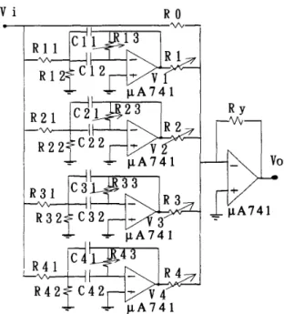
is a second order bandpass filter with unit gain and zero phase at center frequency. There is an in- tuitive explanation on this construction. The bandpass filter Hb:,(jw) is only used t o extract the kth harmonic component A k sin(kwot+&) from input signal z ( t ) undis- tortedly. To subtract the sum of each extracted compo- nent from the input signal is equivalent to eliminate the harmonic interference additive in z ( t ) . Thus, H ( j w ) is a desired comb filter.The circuit used to realize H ( j w ) is shown in Fig.1 for N=4. The relation between input voltage vi and output voltage U, can be written theoretically for ideal opera- tional amplifier as
(4)
where V k is the output voltage of the kth second order narrow-band bandpass filter. After the usual algebra, we obtain the transfer function of kth bandpass filter as fol- lows[4]:
where center frequency f k and quality factor Q k are given by
(7)
Note that B W k is the 3dB bandwidth of the kth bandpass
filter and - -
Based on the above equations, we summarized the entire design procedure as follows. Given center frequency f k and factor Q k , k = 1
..-N,
the circuit parameters can be determined by following steps:Step 1: Suitably choose capacitance c k 1 and c k 2 .
Step 2: R om eq(6) and eq(7) obtain resistance
Step 3: Let gain factor R k l + R i l 2 R k 1 Q 2 in eq(5) be equal to
unity, we get
Step
4:
Let4
=&,
i = 0 . ..
N , then we havevo = -v;
-
5
V kk= 1
Note that there are phase difference of 180 degrees between v; and Vk. For 60Hz harmonic interference elim- ination, we choose center frequency f k = 60k Hz and fac- tor Qk
=
fi.
In order to illustrate the effectiveness ofproposed approach, a simple Spice simulation example is
shown in Fig.2. The Q factors are 10, 20, 30, and 40 for the center frequencies of 100, 200, 300, and 400Hz of the bandpass filters respectively in the simulation example.
RESULT A N D CONCLUSION
The triangular wave of 60Hz was arranged to simulate the harmonic noise. This wave was fed to the four order notch filter (60,180,300,and 420Hz) as the circuit shown in Fig.1. The amplitude of the output was examined to demonstrate the performance of noise cancellation. From Fig.3 we find that using merely the structure of four order notch filter, the power of the triangular wave is remark- ably removed. It is evident that harmonic noise can be significantly suppressed by the circuit.
A circuit to remove four different frequencies that s i m ulate interferent noises had been developed. The circuit contains four individually independent bandpass filters and an inverting amplifier. The architecture of the circuit reveals that it is easy to implement and test. Further- more, the triangular wave testing shows the effectiveness of the circuit to eliminate harmonic interference.
ACKNOWLEDGEMENT
We are very grateful for the support by grants NSC81- 0404-E002-022 from the National Science Council, Tai- wan, Republic of China.
References
(11 Huhta,J.C.,and Webster,J.G.” 60-Hz Interference in
Electrocardiography. ” IEEE Trans. Biomed.Eng.
Vol.BME20, No.2, March, pp.91-101, 1973.
[2] Marshal and Neilson,J.M.” Mains Interference in ECG Recording. ” J . Med. Eng. Technol. Vo1.8, No.4, July- [3] Boyd,E.G.” A Solution to Difficult Power Frequency
Interference on ECG Recordings. ” PACE, V0l.8,
J unuary-February pp. 17-24, 1985.
[4] Sergio Franco ” Design with Operational Ampli-
fiers and Analog Integrated Circuits. ” Singapore : McGraw-Hill Book Co., 1988.
August, pp.177-180, 1984.
V i
R O
-
p A 7 4 1Figure 1: The circuit used to realize H(jw) of eq(3) for N=4. 1 h V 1 b V 0 em 0 (rv 0 c v 0 h V 0 0.v F r q u c n e y
Figure 2: The simulation of active comb filter using eq( 11)
for fundamental frequency lOOHz and N=4.
vo-
.
--Figure 3: Effectiveness test of 4-order notch filter by tri- angular wave.