行政院國家科學委員會專題研究計畫 成果報告
以接觸介面孔隙率為金屬成形摩擦模式參數之理論推導與
實驗驗證
研究成果報告(精簡版)
計 畫 類 別 : 個別型 計 畫 編 號 : NSC 94-2212-E-151-010- 執 行 期 間 : 94 年 08 月 01 日至 95 年 10 月 31 日 執 行 單 位 : 國立高雄應用科技大學模具工程系 計 畫 主 持 人 : 張朝誠 計畫參與人員: 碩士班研究生-兼任助理:陳鴻展、江勝達、周書銘、蘇裕 翔、林明宏 處 理 方 式 : 本計畫可公開查詢中 華 民 國 96 年 01 月 31 日
行政院國家科學委員會補助專題研究計畫
■ 成 果 報 告
□期中進度報告
以接觸介面孔隙率為金屬成形摩擦模式參數之
理論推導與實驗驗證
計畫類別:■ 個別型計畫
□ 整合型計畫
計畫編號:NSC 94-2212-E-151-010-
執行期間:
94 年 08 月 01 日至
95 年 10 月 31 日
計畫主持人:張朝誠
共同主持人:(無)
計畫參與人員:陳鴻展、江勝達、周書銘、蘇裕翔、林明宏
成果報告類型(依經費核定清單規定繳交):■精簡報告
□完整報告
本成果報告包括以下應繳交之附件:
□赴國外出差或研習心得報告一份
□赴大陸地區出差或研習心得報告一份
□出席國際學術會議心得報告及發表之論文各一份
□國際合作研究計畫國外研究報告書一份
處理方式:除產學合作研究計畫、提升產業技術及人才培育研究計畫、
列管計畫及下列情形者外,得立即公開查詢
□涉及專利或其他智慧財產權,□一年□二年後可公開查詢
執行單位:國立高雄應用科技大學 模具工程系
摘要
摩擦是金屬成形製程系統中一個重要的參數,一般採用固定摩擦係數之模式或磨潤模 式作為模擬依據。固定摩擦係數模式之數學形式簡單,但未考慮接觸介面之工件表面鋒 (surface asperity)隨製程變化之事實,而磨潤模式雖已有考慮表面鋒變化之文獻發表,但其 數學形式較複雜,仍無法廣泛應用於一般的金屬成形模擬分析中。因此,本計畫提出一個 以接觸介面孔隙率(porosity)與崔斯卡摩擦模式(Tresca friction model)結合之新的摩擦模式。 此模式乃以工件表面微結構變化為考量,利用工件表面存在表面鋒,且於接觸介面為非完 全壓平之事實,以多孔性材料受力之方式處理,計算接觸介面孔隙率隨金屬成形製程之塑 性變形(更嚴格來說也需包含彈性變形)而發生變化之現象,以孔隙率變化來表示表面鋒 與粗糙度之變化,並將孔隙率導入摩擦模式,用於金屬成形模擬。
本 計 畫 以 圓 環 壓 縮 試 驗 (ring compression test) 與 雙 邊 反 向 擠 出 (double-backward extrusion) 測驗探討摩擦效應與表面粗糙度之關係。利用多孔性材料(porous materials)之降 服準則,推導工件與模具接觸介面之孔隙率與表面粗糙度之關係,將孔隙率之變化導入修 改的崔斯卡摩擦模式(modified Tresca friction model),植入以 C++電腦程式語言撰寫的平面 應變有限元素分析程式,並與實驗結果進行比較。結果顯示所提出之模式可以用於模擬金 屬成形接觸介面之摩擦摩效應。 總之本計畫以新的方法處理金屬成形介面摩擦之問題,並以實驗驗證所提模式之可行 性,不僅可用於一般之金屬成形模擬,且因為以微結構變化為模式推導之基礎,亦可應用 於微尺度之成形模擬。經由理論與實驗之研究,對於如何處理其他工程問題中之介面摩擦 效應也有進一步的貢獻。 關鍵詞:金屬成形、摩擦、表面鋒、孔隙率 Abstract
A new method based on the porosity of the contact interface is proposed to modify the Tresca friction model for the use in metal forming simulation. The method is based on the consideration of the shape change of contact surface at the microscale and the incomplete filling at the contact interface due to exist of surface asperities. During metal forming process, the surface asperities are being altered and mostly flattened because of the plastic deformation and fracture. The surface roughness and friction conditions are thus being changed. This change can be directly related to the porosity at the contact interface. By using the stress conditions at the surface and the yield criteria for a porous material, it is possible to predict the porosity change near the contact region. The predicted porosity is then applied to describe the roughness and thus the friction conditions at the workpiece-die interface in metal forming process.
To determine the friction factors under different surface roughness conditions, ring compression tests and double-backward extrusion tests were performed to obtain a set of calibration curves and the relationship among the porosity at the contact interface, the surface roughness and the friction effect in metal formation process. A new friction model modified from Tresca friction law was then formulated with the porosity to deal with the friction effects. The model was implemented into a developed computer program for the simulation of plane strain
metal forming processes. Some plane strain compression tests were also carried out to verify the proposed friction model. The results show that the new proposed friction model can be used to simulate the friction effect in the metal forming process.
Keywords: metal forming, friction, surface asperity, porosity
報告內容
1. Introduction
Friction is one of important factors in the system of metal forming. It not only increases the required load of forming, but also influences the surface quality of the product and the wear of the dies. As the size of the workpiece decreases, especially in micro metal forming processes, the size effects become significant and the ratio of the surface increases. This situation could enlarge the effects of the friction in metal forming [1]. Thus, to understand the friction phenomena at the workpiece-die interface and to develop friction models for the metal forming process are highly attracted research topics.
Many researchers, such as, Lee and Altan [2], Kobayashi et al. [3], Ramaekers and Kals [4], Sahi [5] and Chenot et al. [6], use the Coulomb friction model or the Tresca friction model to simulate the friction effects at the workpiece-die contact interface in the metal forming process. The factors for the two friction models can be obtained by the calibration curves form the simulated and experimental results of the ring compression tests or the double-backward extrusion tests. The forms of the Coulomb friction model and the Tresca friction model are simple and thus commonly used to model metal forming problems. Nevertheless, the friction factors for the two models are constant values, and the changes of the roughness of the contact surface and the conditions of lubrication are not taken into account. Wilson [7] proposed a model for describing the types of lubrication by considerations of the lubricant thickness and the surface roughness at the contact interface in metal forming operations. Wilson and Sheu [8] proposed a model based on the change of the surface asperity due to the plastic deformation in order to predict the contact ratio in the cold rolling process. The effective surface hardness was also considered in the model. Sutcliffe and Montmitonnet [9] applied the Tresca friction model and the method (Sutcliffe and Le[10]) for estimating the change of the surface asperity to model the rolling of lubricated thin aluminum foils. Hsu and Huang [11] proposed a “realistic friction model”to dealwith thefriction problem in themetalextrusion process.Although the above models based on thin-film lubrication conditions were successfully used to simulate the some forming problems with relatively simple shapes, there are still obstacles to applying those models in the metal forming processes, such as forging and backward extrusion, with transient conditions and relative complex shape of the products. Recently, Yang [12] tried to apply a thin-film lubrication model for three dimensional forming problems but more experimental verifications
are needed. Lo and Tai [13] preformed some experiments for the deformation of the surface asperity and found that the elastic microwedges on the tools surface plays an important role on the variation of the contact ratio which influences the friction effects significantly. In addition, Stupkiew and Mroz [14] proposed an asperity flattening model based on bulk plastic straining but its relations with friction has not been established.
The above literature reviews show that the surface asperities of the workpiece are flattened, thus the contact ratio increases and the surface roughness decreases at the workpiece-die interface during metal forming process. The change of the asperities also affects lubrication regime. Moreover, Doege et al.[15] proposed a yield criterion for porous material to predict the surface roughness of the deformed workpiece and performed some experiments to show the usability of the criterion.
This study is enlightened by the Doege’s study on the porosity of the contact interface. A newly formulated Tresca-based friction model based on the variation of the porosity is proposed and implemented into an in-house plane strain finite element program for the simulation of metal forming process. Experiments including ring compression tests, double backward extrusion tests and plane strain compression tests are carried out to study the relationship between roughness and friction, and also to assess the usability of the proposed friction model.
2. Friction model
The workpiece-die contact interface at the microscale is shown in Fig. 1. The die and the workpiece are considered as rigid and deformable bodies, respectively. During the deformation, the surface asperities of the workpiece are compressed by the dies. Fracture or microwelding effects could also exist at the contact interface. These phenomena cause the change of the porosity and thus the contact and friction conditions which affect metal forming processes significantly.
Doege et al. [15] proposed a model for expressing the relationship between roughness and porosity. By considering the stress conditions and applying the fracture criterion, it is possible to predict the porosity and thus roughness during the deformation. This study is enlightened by the Doege’s research work and proposes a new modeling approach based on the Tresca friction
Fig. 1. Variation of surface asperities and porosity in metal forming process (a) Before deformation (b) After deformation
Imaged area of changing porosity
Surface of die Surface of workpiece
model to deal with the contact problem in metal forming process.
There are many fracture criteria for predicting the porous material in the literatures [15-17]. One of the forms can be expressed as
2 0 2 1 ' 2 BJ C AJ
where J1 is the first invariant of the stress tensor, ' 2
J is the second invariant of the deviatoric stress tensor and 0 is the yield strength of the porous material. The A、B and C are the
constants for the function of the porosity and can be obtained by the literature or form the experimental works. This study uses the experimental results to find the values of A、B and C. The porosity is then combined with the Tresca friction model for metal forming simulation.
The initial value of the porosity can be obtained by the measured surface roughness of the workpiece and dies for the first increment of the simulation. Using the fracture criterion of the porous material and the predicted stress and strain, the newly updated porosity is then estimated and the friction factor of the Tresca model is updated. The extreme values of the porosity might be described as follows: (a) As the value close to one, the contact condition is close to sticking; (b) As the value close to zero, there could be a thick lubrication film with lower a friction effect at contact interface.
The Tresca friction model is expressed as
k
whereis the frictional stress and, k is the shearing strength of the workpiece and is the
friction factor. This study uses the predicted porosity to describe the fraction factor and the Tresca-based model is expressed as
s s s v v v ) , (
where vs is the sliding velocity at the contact interface and can be established by the
porosity and measured data in an semi-empirical form. The proposed friction model not only includes the variation of sliding contact but also takes the flattening of surface asperities into account to simulate the metal forming process.
3. Numerical simulation of metal forming
The material flow of the workpiece is described by a purely viscoplastic behaviour with the neglect of the elastic effects, i.e. the workpiece is a rigid-viscoplastic material. The flow behaviour can be expressed by the Norton-Hoff viscoplastic potential law,(),
1 ) 3 ( 1 ) ( m m K
to form the following constitutive equation:
1 ) 3 ( 2 m K s
where s is the deviatoric stress tensor, K is the material consistency, m is the strain rate sensitivity index and is the effective strain rate with
2 / 1 2 3 2
ij .The material consistency can be a function of strain hardening, e.g.
n K
K 0( 0 )
whereK0material constant, is the effective strain, n is strain hardening index, and 0is a
small positive constant to avoid the numerical problems.
For the special case withm0, the rigid-viscoplastic potential tends to the von Mises flow rule 0 3 2 s
with K0 3, where 0 is the yield stress. The flow rule can be applied to cold metal
forming processes in which the strain rate sensitivity may be not sensitive. It is clear that the deviatoric stress tensor s takes zero-over-zero indeterminate form if the effective strain rate trends to zero. The problem is treated by introducing a small constant 0 and the deviatoric
stress tensor is expressed as
2 0 2 0 3 2 s .
The workpiece is assumed as the incompressibility during the forming process. In terms of the velocity field, the incompressibility condition can be written as
0 ) (v div
where v is the velocity filed. This constraint can be achieved by the Lagrange multiplier method or the penalty method. In this study, the penalty method is used.
At the contact interface s between the workpiece and the die, the stress and the external
traction T can be expressed as follows:
T n
where n is the vector of the normal direction of the contact surface. The relative velocity
s
v between the workpiece and the die is calculated by
d s v v
v
where vdis the velocity of the die. On the contact interface c, the material point to slide on the
die surface can be written as 0
n vs .
This constraint is imposed by the penalty method in this study.
The proposed friction model, , was applied to the modeling of the large deformation of metal forming with isothermal condition. With the penalty method for dealing with incompressibility, the energy of a metal forming system, , can be expressed by the following equation
div v dV vdS T vdS dV m K v s m c
1 2 ) ( ) 3 ( 1 ) ( where V and S are the volume and the sliding contact interface, respectively. is an assigned value for dealing with the incompressible or near incompressible material flows. By applying the finite element method and minimizing the energy with and the Newton-Raphson method, the nodal velocity field t
t t
X can also be obtained by after a small increment of timet by
t V X
Xtt t t.
The strain rate tensor at the end of the increment can be calculated by
T t t t t t t t t t t x v x v 2 1
t t t t
t t t t V V X , The stress tensor can be expressed by means of the strain rate tensor as tt
tt, and the incremental displacement vector t
U
is expressed byUt Vtt. Finally, the strain increment
can also be calculated.
4. Results and discussion
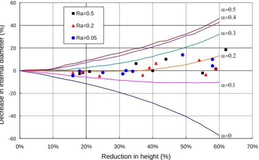
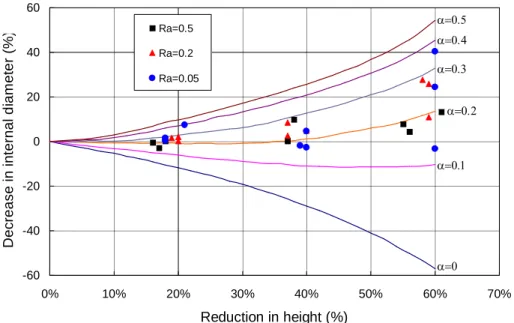
The rings with the outer diameter/inner diameter/thickness equal to 3/1.5/1 mm are compressed by a screw press at constant die speeds of 0.01 0.1 and 1 mm per second without lubrication. By the comparison with a set of calibration curves constructed from a commercial software, the friction factor of the Tresca model is obtained in a range between 0.15 to 0.25 for different roughness of the surface at the die speed of 0.01 mm per second (see Fig. 2). The scattering effect on the measured friction factors gradually increases as the height of ring reduces. In addition, the reduction in the surface roughness described by the arithmetic mean value (Ra) in the range from 0.2 to 0.05 μm does not show the decrease in the friction factor. This might be caused by the present of stronger adhesion friction than abrasive friction. The other reason could be the insensitivity of the ring compression test to local friction effects. It can be seen in Fig. 3 that the measured friction factors slightly increase as the die speed increase from 0.01 (Fig. 2) to 1 mm per second. As the die speed increases, the scattering effect on the measured data becomes larger, especially for higher reduction in the height of the ring. (more results)
-60 -40 -20 0 20 40 60 0% 10% 20% 30% 40% 50% 60% 70% Reduction in height (%) D e c re a s e in in te rn a l d ia m e te r (% ) Ra=0.5 Ra=0.2 Ra=0.05 a=0 a=0.1 a=0.2 a=0.3 a=0.4 a=0.5
Fig. 2. The calibration curves and measured friction factors for different surface roughness at the die speed of 0.01 mm per second
-60 -40 -20 0 20 40 60 0% 10% 20% 30% 40% 50% 60% 70% Reduction in height (%) D e c re a s e in in te rn a l d ia m e te r (% ) Ra=0.5 Ra=0.2 Ra=0.05 a=0 a=0.1 a=0.2 a=0.3 a=0.4 a=0.5
Fig. 3. The calibration curves and measured friction factors for different surface roughness at the die speed of 1 mm per second
5. Conclusions
A new method based on the porosity of the contact interface is proposed and combined with the Tresca friction model for the use in metal forming simulation. The method is based on the consideration of the shape change of contact surface at the microscale and the incomplete filling at the contact interface due to exist of surface asperities. The proposed method is then used in an in-house finite element program for the simulation of plane strain forming process. Experiments including the ring compression test, the double backward extrusion test and the plane strain compression test are also carried out to investigate the relationship between the roughness and the friction factor. The results show that the double backward extrusion test might be a better choice than the ring compression test in the consideration of the sensitivity to the local friction effects. The comparison between the simulated and the experimental results of plane strain compression tests show that the proposed friction model based on the porosity can be used to model the friction effects at the workpiece-die interface in metal forming process.
Acknowledgement
The author wishes to thank the National Kaohsiung University of Applied Sciences for the use of its facilities. The support from the National Science Council under grant NSC 94-2212-E-151-010 is also gratefully acknowledged.
References
1. N. Tiesler, U. Engel, M. Geiger, Forming of Microparts-Effects of Miniaturization on Friction, Advanced Technology of Plasticity, Proceedings of the 6th ICTP, Vol. 2, Sept. 19-24
(1999) 889-894.
2. C. H. Lee, T. Altan, Influence of Flow Stress and Friction Upon Metal Flow in Upset Forging of Rings and Cylinders, Journal of Engineering for Industry, August, (1972) 775-782.
3. S. Kobayashi, S. I.Oh, T. Altan, Metal Forming and the Finite-Element Method, Oxford University Press, 1989.
4. J.A.H. Ramaekers, J.A.G. Kals, Mathematical Representation of Friction in Metal Forming Analysis, Annals of the CIRP. 35/1 (1986) 137-140.
5. M. Sahi, R. Rahouadj, R. Herbach, D. Choulier, The Influence of Viscoplasticity in the Interpretation of the Ring Test, Journal of Materials Processing Technology. 58 (1996) 286-292.
6. J. L. Chenot, L. Fourment, K. Mocellin, Numerical Treatment of Contact and Friction in FE Simulation of Forming Processes, Journal of Materials Processing Technology. 125-126 (2002) 45-52.
7. W. R. D. Wilson, Friction and Lubrication in Bulk Metal-Forming Processes, Journal of Applied Metalwork. 1 (1979) 7-19.
8. W. R. D. Wilson, S. Sheu, Real Area of Contact and Boundary Friction in Metal Forming, International Journal of Mechanical Sciences. 30(7) ( 1988) 475-489.
9. M. P. F. Sutcliffe, P. Montmitonnet, Numerical Modelling of Lubricated Foil Rolling, Science et Genie des Materiaux. May, (2001) 436-772.
10. M. P. F. Sutcliffe, H. R. Le, Measurements of Surface Roughness in Cold Metal Rolling in Mixed Lubrication Regime, STLE Trib. Trans. 43(2000) 39-44.
11. T. C. Hsu, C. C. Huang, The Friction Modeling of Different Tribological Interface in Extrusion Process, Journal of Materials Processing Technology. 140 (2003) 49-53.
12. T.S. Yang, The finite element tribological analysis in metal forming process, Ph. D. thesis, National Yulin University of Science and Technology, Touliu, Yulin, Taiwan, 2004.
13. S.W. Lo, S. D. Tsai, Real-Time Observation of the Evolution of Contact Area Under Boundary Lubrication in Sliding Contact, ASME Journal of Tribology. 124(2) (2002) 229-238.
14. S. Stupkiewicz, Z. Morz, Phenomenological Model of Real Contact Area Evolution with Account for Bulk Plastic Deformation in Metal Forming, International Journal of Plasticity. 19 (2003) 323-344.
15. E. Doege, C. Kaminsky and Bagaviev, A New Concept for the Description of Surface Friction Phenomena, Journal of Materials Processing Technology. 94 (1999) 189-192.
16. H. N. Han, K. H. Oh, D. N. Lee, Analysis of Forging Limit for Sintered Porous Metals, Scripta Metallurgica of Materials. 32(12) (1995) 1937-1944.
17. T. C. Tseng, W. T. Wu, A Study of the Coefficients in Yield Functions Modeling Metal Powder Deformation, Acta Mater. 40(9) 3543-3552.
計畫成果自評
研究內容與原計畫相符程度 研究內容與原計畫大致相符,唯需要更多時間建構軸對稱問題之有限元素分析程式, 因此由原訂針對軸對稱問題更改為平面應變問題之電腦程式寫作。另外,增加平面應變壓 縮實驗之工作,以利驗證所提之摩擦模式。 達成預期目標情況 本計畫完成之工作項目為下列四項: 1. 推導以接觸介面附近的孔隙率為參數的摩擦模式。 2. 建立金屬成形平面應變問題之有限元素分析電腦程式。 3. 執行實驗工作:(1)材料壓縮試驗量測應力應變曲線; (2)環形壓縮試驗量測摩擦係數; (3) 雙邊反向擠出試驗;(4) 平面應變壓縮實驗檢測提出之摩擦模式。 4. 比較與分析所提摩擦模式與其他模式及實驗數據之差異。 其中第 1、3 與 4 項均達成預期目標。唯需要更多時間處理軸對稱問題之有限元素分 析程式寫作,因此第 2 項由原訂針對軸對稱問題更改為平面應變問題之電腦程式建構,另 外第 3 項增加平面應變壓縮實驗之工作,以驗證所提之摩擦模式。 研究成果之學術或應用價值 本計畫所提之摩擦模式以反應接觸之微結構變化為出發點,考慮金屬成形過程工件表 面鋒隨塑性變形之變化而改變接觸介面附近之孔隙率。利用接觸介面之孔隙率為摩擦模式 之參數,將可改善傳統模擬方法以固定摩擦係數值無法反應接觸狀態改變之問題,亦可解 決磨潤模式不易處理動態問題之缺點。此外基於摩擦模式考量微結構之變化,將可有效反 應微金屬成形之介面摩擦問題,並可以運用於其他工程問題中,對摩擦效應做更精確之模 擬分析。研究成果適合在學術期刊發表。 主要發現或其他有關價值 本研究利用介面孔隙率處理摩擦問題,不僅考慮變接觸介面為非完全壓平之事實,並 考慮工件表面鋒之微結構變化,以更直接的方式將示表面鋒與粗糙度之變化導入摩擦模 式。除應用於一般金屬成形之模擬外,將提供一個處理微成形摩擦問題的新研究方向。本 研究是一個處理摩擦問題之新技術,且可廣泛應用於存在摩擦效應之成形問題。可供推廣之研發成果資料表
□ 可申請專利 ■ 可技術移轉 日期:96 年 1 月 28 日國科會補助計畫
計畫名稱:以接觸介面孔隙率為金屬成形摩擦模式參數之理論推導 與實驗驗證 計畫主持人:張朝誠 計畫編號:NSC 94-2212-E-151-010 學門領域:機械固力技術/創作名稱
利用接觸介面孔隙率之金屬成形摩擦模式發明人/創作人
張朝誠 本技術利用接觸介面孔隙率與崔斯卡摩擦模式之結合以處理 金屬成形接觸介面之摩擦效應。此模式乃以工件表面微結構變化為 考量,利用工件表面鋒之存在接觸介面為非完全壓平之事實,以多 孔性材料受力之方式處理,考慮接觸介面孔隙率隨金屬成形製程之 塑性變形而發生變化之現象,將孔隙率導入摩擦模式,用於金屬成 形模擬。技術說明
A new method based on the porosity of the contact interface has been developed to modify the Tresca friction model for the use in metal forming simulation. The method is based on the consideration of the shape change of contact surface at the microscale and the incomplete filling at the contact interface due to exist of surface asperities. During metal forming process, the change of the surface roughness and friction conditions can be directly related to the porosity at the contact interface. The predicted porosity is then applied to describe the roughness and thus the friction conditions at the workpiece-die interface in metal forming process.