IEEE SIGNAL PROCESSING LETTERS, VOL. 15, 2008 349
Optimal Delay Estimation for Phase-Rotated Linearly
Interpolative Channel Estimation in OFDM and
OFDMA Systems
Kun-Chien Hung and David W. Lin, Senior Member, IEEE
Abstract—We consider the phase-rotated linearly interpolative
channel estimation technique for multicarrier transmission. The technique models the channel frequency response between two nearby subcarriers as the product of a linear function and a linear-phase factor, where the linear-phase factor may be equiv-alently modeled in the time domain as a reference delay dubbed the anchor delay in this work. We show that the performance of the technique is a fourth-order function of the channel path delays and the anchor delay. We derive a method to estimate the optimal anchor delay. Analysis and simulation in a context of Mobile WiMAX downlink transmission show that, with the proposed an-chor delay estimate, we can attain better performance in channel estimation than conventional linear interpolation and a previously proposed method of phase-compensated linear interpolation.
Index Terms—Channel estimation, delay estimation, IEEE
802.16e, orthogonal frequency-division multiple access (OFDMA), orthogonal frequency-division multiplexing (OFDM), WiMAX downlink.
I. INTRODUCTION
L
INEAR interpolation is a simple and efficient method for channel estimation in orthogonal frequency-division multiplexing (OFDM) and orthogonal frequency-division mul-tiple access (OFDMA) systems. It first estimates the channel responses at some pilot subcarriers by some means. Then linear interpolation is carried out between neighboring pilot frequen-cies. Hence, it is applicable when the coherent bandwith of the channel is larger than the pilot subcarrier spacing. However, its performance depends on both the symbol timing error [1] and the amount of channel delay spread. While the former can be mitigated by accurate symbol time synchronization, the latter is more involved and deserves a closer look. Later derivation will show how larger delay spreads may lead to greater performance loss.To mitigate the performance loss due to large delay spreads, we consider using phase-rotated linear interpolation in channel estimation, as has also been proposed in [2]. The approach is motivated by the fact that delay in time corresponds to linear
Manuscript received October 25, 2007; revised December 6, 2007. This work was supported by the National Science Council of Taiwan R.O.C., under Grant NSC 96-2219-E-009-003. The associate editor coordinating the review of this manuscript and approving it for publication was Prof. Kainam Thomas Wong.
The authors are with the Department of Electronics Engineering and Center for Telecommunications Research, National Chiao Tung University, Hsinchu, Taiwan 30010, R.O.C. (e-mail: [email protected]; [email protected]. tw).
Color versions of one or more of the figures in this paper are available online at http://ieeexplore.ieee.org.
Digital Object Identifier 10.1109/LSP.2008.919844
phase shift in frequency. By augmenting simple linear interpo-lation with a linear-phase factor, we can better model the fre-quency response of a multipath channel. Let the equivalent delay of the linear-phase factor be termed the “anchor delay” and de-noted . It may be considered a reference path located at units of time after the symbol start time found by the synchro-nizer. A key issue now is the determination of the anchor delay. Hsieh and Wei [2] adopt Kay’s single-frequency estimators [3] for it. As shall be elaborated later, their estimate of choice can be interpreted as an approximate center of mass (COM) of the path energies of the channel.
Thus far, no analysis of the optimal anchor delay from the channel estimation perspective has appeared. In Section II of this letter, we derive an analytical expression for the MSE performance of phase- rotated linear- interpolation channel
estimation (RICE). Then in Section III, we derive the optimal
anchor delay, where we also comment on the relation between the COM delay and the optimal delay. As a practical example, in Section IV, we apply the proposed technique to WiMAX downlink channel estimation and evaluate its performance through both analysis and computer simulation.
II. PHASE-ROTATEDLINEAR-INTERPOLATIONCHANNEL
ESTIMATION ANDITSPERFORMANCE
Consider a typical baseband channel impulse response (1) where is the relative delay of the th path and is its complex gain. Let , where and are, respectively, the discrete Fourier transform (DFT) size and the sampling pe-riod used in OFDM/OFDMA signaling. Then the channel fre-quency response can be expressed as
(2) where is normalized frequency (in units of OFDM/OFDMA
subcarrier spacing), , and is to
be determined. With RICE, the channel response at an interme-diate frequency between two pilot frequencies and is interpolated as
(3) where and are some channel estimates as-sumed to have been obtained using the pilot signal.
To find its performance, neglect the channel noise for now and consider only the modeling error. Assume and
350 IEEE SIGNAL PROCESSING LETTERS, VOL. 15, 2008
. Let the pilot subcarriers and be chosen randomly. Then the MSE in channel estimation at the
th intermediate subcarrier is given by (4) at the bottom of the page. denotes averaging over all frequencies and
. We get
(5) and thus
(6) Taking the Taylor series expansion of , we find that the terms below order 4 are canceled out in and that the fourth-order terms dominate its numerical value. Thus
(7) Averaging over yields the overall MSE as
(8)
where .
Several observations can be made of the last equation. First, the difference between RICE and the conventional linear-inter-polation channel estimation (LICE) lies in the value of . For LICE, and the resulting overall MSE is
(9) For RICE, the additional freedom in choice of gives it the ability to surpass the performance of LICE. Secondly, the overall MSE in either case is dependent on the fourth powers of the path delays . Thirdly, the overall MSE increases with the fourth power of the pilot spacing in both cases.
More accurate approximations to the overall MSE can be obtained by retaining more terms in the Taylor series. For ex-ample, in the case of LICE, if the channel has a very long delay spread, then a sixth-order approximation may provide signifi-cantly better accuracy as follows:
(10)
where .
III. ESTIMATION OF THEOPTIMALANCHORDELAY
To find the optimal anchor delay, differentiate with respect to and set the result to zero. Let the resulting delay be termed the MSE delay and denoted . We get
(11) However, to solve it requires knowing and , which are available only after channel estimation. To sidestep this problem, note that an equivalent cost function to can be formulated in terms of as (12) Since (13) we have (14) , ,
, and collects the terms that are not a function of . Note that, in obtaining (14), we have tacitly assumed the presence of a number of equally spaced “pilot trios.” This is not a fundamental limit to the proposed technique, as a more general
HUNG AND LIN: OPTIMAL DELAY ESTIMATION FOR PHASE-ROTATED LINEARLY INTERPOLATIVE CHANNEL ESTIMATION 351
form of (14) can be derived for arbitrary pilot structures. For space reason, we omit its discussion.
To find the MSE delay, one way is to solve the equation for . This leads to the equation
(15)
where and , . Letting
, we can convert the equation to
(16)
in which , ,
, , and
. Quartic equations such as this have a known general solution whose calculation involves a few elementary arithmetic operations and the computation of several square roots and cubic roots [4].
An alternative method, perhaps simpler than solving the quartic equation, is to search over a range of values of (or equivalently, ) for the one that minimizes . The search range does not have to form a continuum but can be discrete, for by (8), a little change in would not change the overall MSE by much. Experience shows that a resolution in on the order of to is sufficient. Also, we only need to search over
the range . Moreover, the system is
usually designed such that the channel coherence time would span at least a few OFDM/OFDMA symbols. Then would stay relatively close from one symbol to the next. Hence, the search range for each subsequent symbol can be narrowed to a small region near the current solution. Depending on the channel condition, we may even update the anchor delay only once every few OFDM symbols.
A. Relation of COM Delay to MSE Delay
Consider a design objective that minimizes not the MSE but the variation of with frequency in some sense as follows:
(17) The value of that minimizes this function is given by
(18)
which is the COM of the path energies. Approximating
by , we obtain
(19) which is the estimator proposed in [2]. Therefore, the COM delay minimizes a different objective than the MSE and gives a solution that is suboptimal in the MSE sense.
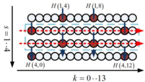
Fig. 1. Cluster structure in Mobile WiMAX downlink and corresponding channel estimation method.
IV. APPLICATIONTOWIMAX DOWNLINKCHANNEL
As a practical example, consider the OFDMA Mobile WiMAX downlink. In partial usage of subchannels (PUSC) transmission, the transmitted signal is made of some “clusters” where a cluster consists of 14 consecutive subcarriers with alternating structures in two successive OFDMA symbols, as illustrated in the dashed rectangle in Fig. 1.
Let denote the channel response at subcarrier of
symbol , where and , and consider
channel estimation for symbols 2 and 3. Consider the following estimation method, which makes use of information from the previous and the next symbols: 1) do least-squares (LS) channel estimation at pilot subcarriers (which simply divides the re-ceived signal value by the pilot value at each pilot subcarrier to obtain the channel response estimate at that frequency); 2) do linear interpolation along the time axis to obtain , , , and (as indicated by the dash-dot arrows in Fig. 1); 3) estimate one single anchor delay for both symbols 2 and 3 using the available channel estimates so far; and 4) perform RICE to obtain channel estimates for the remaining subcarriers in the two symbols (as indicated by the dotted ar-rows in Fig. 1).
As can be seen, some slight modifications of the basic method are made to accommodate the particular pilot structure. First, in step 2, time averaging is used to obtain additional reference points for RICE in symbols 2 and 3. Secondly, though not nec-essary, in step 3, only one anchor delay is calculated for both symbols. Lastly, in step 4, we estimate
by phase-rotated linear extrapolation (rather than interpolation) using and . The equation is a simple modifica-tion of (3) and is thus omitted. Note also that a corresponding LICE version of the method is obtained by omitting step 3 and letting in step 4.
Incidentally, we note that due to the given signal structure, linear-interpolation channel estimation can perform better than higher-order methods such as cubic interpolation [2] and raised-cosine interpolation [5]. Compared to linear minimum mean-square error interpolation [2], it also strikes a competitive bal-ance between performbal-ance and complexity.
A. Performance Analysis
Four factors contribute to the channel estimation error, which are: channel noise (assumed additive white Gaussian, i.e., AWGN), model error from time-domain interpolation, model error from frequency-domain interpolation, and anchor delay estimation error. It turns out that we can disregard the anchor delay estimation error because in a low signal-to-noise ratio (SNR), the channel estimation error is dominated by the contri-bution from AWGN, whereas in a high SNR, the anchor delay can be estimated accurately. Thus, we only need to consider
352 IEEE SIGNAL PROCESSING LETTERS, VOL. 15, 2008
the effects of the other three factors. For space reason, we only give an outline of the analysis.
Let denote the average MSE in channel estimation at subcarrier in symbol , where the average is taken over all channel realizations. In step 1 of the proposed method, the estimation error comes from AWGN only. As the pilots are
BPSK-modulated, we have , where
and is the variance of the AWGN. For step 2, both the AWGN and the time-domain model error contribute to the
estimation error. We have , where
and is the model error from time averaging, given by
(20) Assume that the paths are Rayleigh faded. Then
(21) , is the peak Doppler shift of path times the OFDM/OFDMA symbol period, is the Bessel function of the first kind of order 0, and the last expression is obtained by approximating the Bessel function with second-order Taylor se-ries expansion. Note that is independent of both and . Fi-nally, for step 4, we get
(22) where is as given in (8) for RICE or in (9) for LICE. As to
and , we have
(23) where denotes the MSE in channel estimation by phase-rotated linear extrapolation to a distance of subcarrier spac-ings. By a similar derivation to (7), we get
(24) For conventional non-phase-rotated extrapolation, .
Taken together, the average MSE per data subcarrier in the estimated WiMAX downlink channel is approximately
(25)
B. Numerical Results
We simulate WiMAX downlink transmission with a 2.5-GHz carrier, 10-MHz bandwidth, 1024-point DFT, and 128-point cyclic prefix. The user channels are 3-path channels with power
profile (in dB) and delay profile (in
samples), which are based on the SUI-5 channel model [6]. The original SUI channels are quasi-static, but we consider a 100 km/h mobile speed, corresponding to . The simulated channels are block time-varying, with each
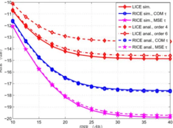
Fig. 2. Normalized MSE (relative to channel power gain) in Mobile WiMAX downlink channel estimation, where “sim.” stands for “simulation” and “anal.” for “analysis.”
path simulated using Jakes’ model. We assume perfect symbol timing, that is, the receiver acquires the timing of the first path accurately. In RICE, the anchor delay is obtained by the search method with resolution.
Fig. 2 shows the channel estimation MSEs under different methods. For RICE, the analytic results based on fourth-order approximation match the simulation results closely under both the COM delay and the MSE delay. For LICE, the sixth-order approximation gives a better match. At low SNRs, AWGN dom-inates the performance, thus the nearly slopes in the curves in the low SNR region. Both LICE and RICE show error floors at high SNR values due to model error, but for RICE with MSE delay, the floor is the lowest.
V. CONCLUSION
We considered the phase-rotated linearly interpolative channel estimation technique for OFDM and OFDMA systems. We showed that a key performance issue was the selection of the anchor delay, particularly when the channel had a large delay spread. We derived a method to estimate the optimal anchor delay. As a practical example, the proposed technique was adapted and applied to OFDMA Mobile WiMAX down-link channel estimation. Analysis and simulation both showed that the proposed scheme could yield the lowest model error and thus result in better performance than conventional linear interpolation and a previously proposed method of phase-com-pensated linear interpolation.
REFERENCES
[1] J. Park et al., “Performance analysis of channel estimation for OFDM systems with residual timing offset,” IEEE Trans. Wireless Commun., vol. 5, no. 7, pp. 1622–1625, Jul. 2006.
[2] M.-H. Hsieh and C.-H. Wei, “Channel estimation for OFDM systems based on comb-type pilot arrangement in frequency selective fading channels,” IEEE Trans. Consum. Electron., vol. 44, no. 1, pp. 217–225, Feb. 1998.
[3] S. Kay, “A fast and accurate single frequency estimator,” IEEE Trans.
Acoust., Speech, Signal Process., vol. ASSP-37, pp. 1987–1990, Dec.
1989.
[4] W. H. Beyer, Ed., Standard Mathematical Tables, 25th ed. Boca Raton, FL: CRC, 1973, pp. 12–12.
[5] P.-Y. Tsai and T.-D. Chiueh, “Frequency-domain interpolation-based channel estimation in pilot-aided OFDM systems,” in Proc. IEEE 59th
Vehicular Technology Conf., May 2004, vol. 1, pp. 420–424.
[6] Channel Models for Fixed Wireless Applications, IEEE 802.16.3c-01/ 29r1, Feb. 23, 2001.