RAAEDS: A Requirements Analysis Aid for Embedded Digital Systems
6
0
0
全文
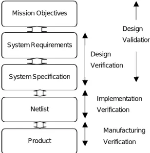
(2) original problem statement (from the user). These account for up to 85% of requirement errors”[5]. According to statistics shown in Boehm’s paper [1,3], for large software projects , the cost of up to 200:1 is possible if the requirements errors cannot be found and corrected earlier in the system development cycle. Please refer to Table 1.. subsystem, or a whole interacting with one of its subsystems as an environment for this subsystem. This environment will in general provide asynchronous stimuli, which is to be synchronized with the operation of the system; i.e. the systems to be discussed are basically synchronous real-time ones, instead of the batch-processing ones. In a real-time system meant here, the arriving time of the inputs from the As environment are in general not predictable, and their corresponding responses are expected to be generated within a finite and specified delay [8], which is required by or implied in the original mission objectives. While in a batch processing system, all the inputs to be. Table 1 The relative cost to repair a software error in different stages of system life cycle [1] Stage. Relative Cost of Repair. Requirements. 0.1 – 0.2. Design. 0.5. Coding. 1. Unit Test. 2. Acceptance Test. 5. Maintenance. 20. As another set of numerical evidence, in Lutz’s study of the software requirements errors in safety-critical embedded systems [6] she showed that only three of the safety-critical faults found were programming mistakes, and very few problems were attributed to failures in programming occurring during flight. Among the rest of the faults, approximately three-fourths is due to “function faults” (faults within a single software module), and about one-fourth is due to “interface faults” (interactions with other modules or system components). Among the function faults, two thirds of them were attributed to flawed requirements, omissions, impreciseness, unsystematic, or wrong specifications of requirements; while one third of them were due to incorrect implementation of requirements (i.e. faulty design or algorithms). Requirement errors in software system design seem to be a serious problem [6,7]. From these statistical figures, it seems proper to say that the errors in the software specifications (similarly in hardware specifications) happen very often and can be very expensive to correct if they are not found earlier enough. Besides, the manual inspection, according to the system designers' own experiences and intuition, with the help of some kind of good design criteria checklist, is an important way of finding errors in a system requirement or a specification document.. Figure 2 The type of systems concerned in this study processed line up in some kind of queue(s) and are to be processed according to certain priority policy, such as “FIFO (first in first out)”. Usually, a batch-processing system does not specify the delay between the inputs and their corresponding outputs. The delay usually depends on how many higher-priority and/or earlier-arriving jobs are waiting for processing. The users usually expect the delay. In this paper, a system is referred as a set of functional elements organized together to satisfy a set of mission objectives. These elements usually include hardware ones and software ones. A digital system refers to a system whose hardware elements are purely digital (software is stored as binary digital information in the memory elements), instead of analog, although the interfaces to the physical environment may need analog transducers plus analog to digital converters. The digital systems mainly concerned are single-processor (or CPU, the Central Processing Unit) systems, but the developed checklist can also be applied to multi-processor systems as well, although the considerations may not be enough, say, how to spot the errors in the communication protocols among different processors are not thoroughly considered. On the other hand, from the hierarchical point of view about a system, the interactions among the subsystems or those among the modules in a subsystem are basically following the same interfacing principle. Therefore, a general checklist of criteria or guidelines applied to all of them would help to identify the potential interfacing problems that have to be considered.. 2. The Type of Systems Concerned in This Study In this paper, the digital systems to be discussed are something like that depicted in Figure 2. Although this system model by no means covers all possible existing digital systems, it does cover a large number of useful systems. As shown in Figure 2, a system is interacting with its environment; namely, the system receives stimuli signals from the environment and responds to these signals by generating responses, which will be sent to the environment to meet needs of a system. The stimulus signals are converted into digital binary signals before they can be processed by the internal digital information processing subsystem. That is, the digital systems concerned are the binary digital systems. The environment of a system here can be a physical one from which an analog stimulus can be detected and can be converted into a binary digital information for further processing, such as human operators, a hardware subsystem as an environment for a software. 3. Taxonomy and Samples of Design Guidelines According to the ANSI/IEEE-ANS-7-4.3.2-1982 standard, NASA-STD-2100-91 Documentation Standard, Jaffe et al’s paper [12], and the author’s own investigation, the important groups of problems. 2.
(3) that should be considered carefully in system design are summarized below. If available, some example application case will be put alongside.. (4) Input Trigger Stimuli Sample Guideline 4: (a) If a system is required to process multiple simultaneous stimuli, then the timing relationships among them should be investigated for possible affection on the behaviour of the system. (b) One or more of the stimuli must be buffered for later processing. e.g.4 In a system equipped with two buttons, “start” button and “stop”, the possibility that both of these buttons are pressed simultaneously should be considered in the specification, no matter whether only one button is required to initiate an action or not.. (1) Initialization/Finalization Sample Guideline 1: The specification of a subsystem initialization process has to be ensured for no adverse effect on other subsystems or even the whole system’s initialization process, through some common facility or medium, if any, such as a power line, a data bus, a control bus, an address bus, a radio, an optical-electrical data link, a shared memory, a public queue, and so on. e.g.1 In the incident of the failure of the launch of first shuttle, Columbia, showed that in a bus initialization routine, a slightly increased time-delay constant than before, was put into the timer queue without being noticed. As a result, it caused unexpected influence on the initialization of the backup computer system --the calculation of start time in the first GPC (General Purpose Computer), through the common medium timer queue in its operating system. This delay constant, without being noticed by the designers, was mistaken as the data for computing starting time of the system. It therefore caused unexpected system initialization and synchronization failure. As a result, the launch failed and was put off for two days. [13]. (5) Output Specification/environment Capacity Sample Guideline 5 :Internal State Display Are all critical system’s internal states clearly and correctly displayed at the desired time for the operators to know what the system’s current status is for reliable and easier controlling of the system? e.g.5 In the Three Mile Island accident, the control indicators did not show the actual positions of the valves but instead the intended positions. The resulting ambiguity as to the actual settings caused enormous confusion. [2]. (2) Synchronization Sample Guideline 2: If there are subsystems that use different system clocks, it should be ensured that these different clocks are directly derived from the same master clock (therefore, they are synchronized one another), and some coordination method is used to provide an identical start-up time for all of them. e.g.2 On 10 April, 1981, in the launch of first shuttle Columbia, the backup computer and the four primary computers were one time unit out of phase during the initialization, as a result of an extremely subtle 1-in-67 chance timing error. [2,13] (3) Input/Output Information Description: Sample 3: Precision of Data Representation (a) Does the way to represent the data and the rounding scheme adopted in the specification allow the system to work in a desirable way with enough precision? (b) Is the precision too coarse to differentiate two different control data? (c) Is the precision too fine to meet the required system performance and/or to increase the system cost beyond budget? (d) Are different precisions used in different subsystems or modules? Are they compatible with one another? When they encounter, will they cause problems? e.g.3 During the Persian Gulf War, the Patriot system was initially regarded as highly successful, but in the subsequent analyses, the estimates of its effectiveness downgraded from 95% to 13% (or less). This clock drift over a 100-hour period resulted in a tracking error of 678 metres, which was blamed for the Patriot missing barracks in Dhahran, killing 29 and injuring 97. The later report stated that the software used two different and unequal versions of the number 0.1--- in 24-bit & 48-bit representations. [2]. (6) Output to Input Trigger Stimuli Relationships Sample Guideline 6 : Closed-loop Control (a) In a safety-critical system, an input that the system can use to detect the effect of any output on a process should be specified. The specification should include the proper checks on these inputs in order to detect failures or errors. (b) A mechanism should be used to compare the actual effects of outputs from the system with the predicted effects, that is, a feedback loops (including echoes). [12] e.g.5 In a ferry accident, some time after the captain issued a command to lift up the door, he thought the door should have been closed. He then commanded to sail the ferry off the dock. The ferry sank and caused the accident. (7) System Loading/buffering Sample Guideline 7: If a system is interacting with an environment constantly providing input stimuli in an unpredictable manner, and if it uses any kind of buffers to hold the input stimuli for later processing, then there is always a probability that the buffer may overflow. A strategy to handle the possible buffer overflow and recovery method should be specified. (8) System State Transitions Sample Guideline 8: Correctness of State Transitions Every single precondition, any minterm in the guarding logical predicate, and any datum involved in deciding an output response or a state transition, should be checked for validity and correctness, according to the mission objectives and the system requirements. e.g. A state transition statement, like If (A or B) then state C transits to state D, should be checked for the correctness and validity of all component minterms of (A or B), namely, A’B, AB’, and AB. (9) Errors/faults Handling Sample Guideline 9: It is never safe to remove protections, unless it is proved that the stimulating event(s) will never happen.. 3.
(4) e.g.9 In Therac-25 accidents, it was found that hardware interlock was omitted, because it was thought that it would be implemented in software. However, in a case that an operator tried to correct her wrong operation, an unexpected software bug triggered the accident.. (13) Hazard Analysis Sample Guideline 13: All paths from hazardous states must lead to safer states. In other word, the system should be designed in a way that the system will most probably stay in a safer state while the system fails. e.g.13 In Galileo spacecraft project many of the software related errors (approximately 20%) involved the on-board autonomous error-recovery responses incorrectly included or omitted actions that allowed hazardous states to be entered or re-entered. Examples of such actions are turning off Gyros, switching to backup memory, or disabling certain software process in a particular mode. [15]. (10) Input Information Gathering: Whenever there is an event coming into the input information gathering module (IIGM), accurate information corresponding to that event must be produced. On the other hand, if there is information produced from the IIGM, then it must imply that there is a corresponding event coming into IIGM, not other events. During the transmission process, the information should be kept correct, without being corrupted. E.g.10 Input Data Seemingly Healthy But Actually Obsolete In validating the requirements specification of a spacecraft project in Jet Propulsion Lab, the validators found that a failure mode was not identified before. Inaccurate input data from a sensor could in effect disable the execution of a software response that was needed. This may happen when the input data appeared to be healthy, but was actually reflecting an obsolete state. After searching the possible circumstances in which the software would actually receive seemingly healthy but actually obsolete data, the validators found that the current interface requirements allowed obsolete data from a failed sensor to be continually sent to the software. If the sensor failed with healthy valves, then that data would continue to be used indefinitely to cause the failure mode. Later, the requirements were modified to have the data from a sensor pass a test first, before the software uses them to activate a response. [2]. (14) Assumptions Sample Guideline 14: If an operational scenario is possible, then it will happen. Unless there is something designed to make the possible become impossible, all possible input combinations would finally happen. e.g.14 An aircraft was damaged when the computer raised the landing gear in response to a test pilot’s command while the aircraft was standing on the runway. It seems that the designer assumed raising-the-landing-gear command would not be issued while the aircraft was standing on the ground. [2] (15) Modeling Sample Guideline 15: A model needs to be simple, but includes all concerned parameters and assumptions and no fewer. The assumptions and parameters should also be carefully reviewed, such that it is accurate enough for its behavior desired, especially in the area of discontinuities. [2] e.g.15 Afterward analysis about the structural failures of the Electra aircraft were apparently due to simulation having omitted dynamic effect (gyroscopic coupling) that had never been significant in plane with piston engine. [2]. (11) Interrupt Handling Sample Guideline 11: (a) Don’t use interrupts in the system, unless it is nece ssary. (b) If it is indeed used, then the fact that they can come at any awkward time should be considered, such as during (1) the storing period of the status of current system state, (2) the critical data adjusting period, (3) a higher level operation regarded as an atomic action, but in lower level of granularity, it may consist of two or more smaller operations, (4) the different operation modes switching period, (5) a state transition period, (6) error recovery period, and so on.. (16) Design Methodology Sample Guideline 16: Design Decisions Evaluation: The rationale of every design decision should be recorded and carefully evaluated for its possible influence on the system behavior, preferably by other experts of the team or of other teams. e.g.16 In Ariane5 Flight 501 failure report, several design decisions were found to be fatal to the system. (1) In order to reach the maximum workload target of 80% having been set for the IRS (Inertial Reference System) computer, some conversion from 64-bit floating point to 16-bit signed integer were not protected. As a result, an unexpected data value caused the conversion fail and the IRS software to raise the software exception in which a diagnostic bit pattern was produced. The On-board Computer then misinterpreted this diagnostic bit pattern as flight data and finally caused the launcher disintegrate. (2) The specification about the exception-handling mechanism also represented a wrong design decision. It was found that the system specification of the exception-handling mechanism stated that: In the event of any kind of exception, the IRS (Inertial Reference System) should be shut down. It was the decision to shut down the IRS processor that was proved fatal. Please refer to Failure Case No.9 in Chapter 4 for more details.. (12) Existing Subsystems Reuse Sample Guideline 12 (a) Any subsystem that is to be embedded into a system must be fully defined and documented. For examples, its inputs, its outputs, its internal functions, its original embedded design rationales, its assumptions about the operational environment, its design constraints and limitations, should be fully explored. (b) Besides, its interaction with the rest of the system should also be thoroughly analyzed for without having unwanted behaviors. e.g.12 Therac-25: Much of the software in the Therac-25 medical electron accelerator, which lead to massive overdoses of radiation and subsequent deaths of six patients, had been used in an earlier machine without accident. [2]. 4.
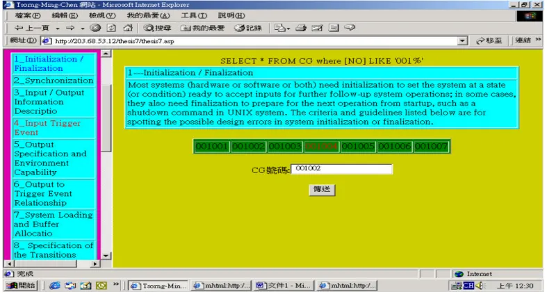
(5) (17) Design Constraints/Feasibility Sample Guideline 17: Environmental Constraints Any sensitive part in the system, which will easily pick up an interference that is intrinsic in the operational environments, should be identified. e.g.17 9 from 16 robotic accidents in Japan are due to interference from the environment to the system. [2]. Nevertheless, in order to make the database more comprehensive in practice, more guidelines need to be put in the database.. (18) Communication Protocol Sample Guideline 18: In a communication protocol definition, in case that each of multiple hardware modules in the system would issue a command at the same time, the rules in the protocol should define the coordination of these commands in a way for the system to react desirably, say, without causing mutual conflicts of actions among modules, or resulting in modules falling into a simultaneous waiting state --- a deadlock state.. References. Acknowledgements This work is supported by National Science Council, Republic of China on Taiwan, under the grant number NSC89-2213-E-014- 024.. 1. Alan M. Davis, “Software Requirements – Objects, Functions, and States,” Englewood Cliffs, NJ: PTR, Prentice Hall, 1993 2. Peter G. Neumann, “Computer-Related Risks”, Addison Wesley, 1995 3. Barry W. Boehm, “Verifying and Validating Software Requirements and Design Specifications”, IEEE Software, pp75-88, Jan. 1984, 4. Donald J. Flynn, “Information Systems Requirements : Determination and Analysis”, McGraw-Hill International (UK) Limited, 1992 5. C.V. Ramamoorthy, and G.S. Ho, “A Design Methodology for User Oriented Computer Systems”, Proceedings of National Computer Conference, pp953-966, 1978 6. Robyn R. Lutz, “Analyzing Software Requirements Errors in Safety-critical Embedded Systems”, The second International Symposium on Requirements Engineering, San Diego, CA, USA, pp126-133, Jan. 4-6 1992 7. John Rushby, and M. Srivas, “Formal Methods and the Certification of Critical Systems”, Technical Report CSL-93-7, Computer Science Laboratory, SRI International, Menlo Park, CA 94025, pp15-16, pp125-139, December 1993, 8. T.M. Chen, and B.R. Wilkins, “A Set of New and Efficient Formulae for Buffer Size Analysis of Real-Time Systems Using M/G/1 Models”, Proceedings of Fourth International Workshop of Real-Time Computing Systems and Applications, Taipei, Taiwan, pp186-190, 27-29 Oct. 1997 9. Derek J. Hatley, and I. A. Pirbhai, “Strategies for Real-time System Specification”, Dorset House Publishing, New York, 1987 10. Jeffrey O. Graby, “System Validation and Verification”, CRC Press, Chapter 1, pp1-50, 1998 11. Douglas Sailor, “System Engineering: An Introduction”, from “Tutorial: System and Software Requirements Engineering”, R.H. Thayer and M. Dorfman (Eds.), IEEE Computer Society, Washington, D.C., pp35-47, 1990 12. M.S. Jaffe, N.G. Leveson, M.P.E. Heimdahl, and B.E. Melhart, “Software Requirements Analysis for Real-time Process-control Systems”, IEEE Transactions on Software Engineering, Vol. 17, No. 3, pp241-258, March 1991 13. John R Garman, “The ‘BUG’ Heard Round the World”, ACM SIGSOFT, Software Engineering Notes, Vol. 6, No.5, pp3-10, October 1981 14. Phillip A. Laplante, “Real-time System Design and Analysis – An Engineer’s Handbook”, 2 nd Ed., IEEE Press, p13, p157, pp179-181, pp246-253, 1997 15. Lutz, Robyn R. (1993), "Targeting Safety-related Errors During Software Requirements Analysis", ACM SIGSOFT'93 (1993 Symposium on Foundations of Software Engineering), Los Angeles, CA, USA, Published as ACM Software Engineering Notes, Vol.18, No.5, pp 99-106. 4. The Database for Design Guidelines The database of the design guidelines is implemented in ASP language and in the Microsoft Access environment. There are totally eighteen categories of guidelines, and one hundred and five design guidelines. This database is intended to make the access of the guidelines easier to facilitate the design validation process. The design guidelines can be retrieved by keywords, or by the guideline category number. Besides, the users can access the system failure cases (if available) accompanying each design guideline by simply clicking the identification numbers of the system failure cases. Furthermore, because the database is implemented in ASP language for Internet environment, it can be put into a server and can be accessed through Internet. Therefore, it is a handy tool for refining and validating a requirements or a specification document. In the future, more guidelines and more failure system failure cases will be added so that it would become an even more comprehensive tool for requirements and specification analysis. Two screens of the database are shown respectively in Figure 3 and in Figure 4.. 5.. Conclusions. In designing a digital system, defining a correct functional system specification is the first major task in the system design life cycle. However, since a specification is evolved from the a documents of mission objectives or requirements, which is usually written in a natural language, there isn’t anything precise to verify against. Besides, a lot of engineering judgments and tradeoffs are involved in this process. As a result, only manual validation is possible, according to some formulated criteria or guidelines as a checklist to validate the easily neglected design aspects (although automatic tools, if available, may be helpful, but only for those formally formulated routine checks). Please note that if a design error is not captured earlier enough, then its total amending cost could be 200 times or more costly. Therefore, how to spot this kind of design errors in the early stage is important. In this paper, a set of design guidelines for validating functional requirements or specifications of digital systems are developed and presented. Whenever available and appropriate, relevant system failure cases are also given to illustrate the usefulness of the guidelines. It can be seen that by going through these guideline database, the users can spot many subtle design errors happening in the past.. 5.
(6) Figure 3 Illustration of the database. The guidelines can be accessed through clicking the category number and then the guideline number or simply clicking the category and guideline number buttons in sequence to access them. Figure 4 The screen results from the actions taken in Figure 3. The desired design guidelines are in Category Number 1 --Initialization and Finalization, and the second guideline is shown as the result of searching the database. 6.
(7)
數據
![Table 1 The relative cost to repair a software error in different stages of system life cycle [1]](https://thumb-ap.123doks.com/thumbv2/9libinfo/8916817.261684/2.892.52.431.309.484/table-relative-repair-software-error-different-stages-cycle.webp)
相關文件
An additional senior teacher post, to be offset by a post in the rank of CM or Assistant Primary School Master/Mistress (APSM) as appropriate, is provided to each primary
An additional senior teacher post, to be offset by a post in the rank of CM or Assistant Primary School Master/Mistress (APSM) as appropriate, is provided to each primary
An additional senior teacher post, to be offset by a post in the rank of Certificated Master/Mistress or Assistant Primary School Master/Mistress as appropriate, is provided to
An additional senior teacher post, to be offset by a post in the rank of APSM, is provided to each primary special school/special school with primary section that operates six or
(b) The Incorporated Management Committee may approve leave of various kinds to teaching and non-teaching staff employed under the Salaries Grant, paid or no-pay, in
(ii) “The dismissal of any teacher who is employed in the school – (a) to occupy a teacher post in the establishment of staff provided for in the code of aid for primary
An additional senior teacher post, to be offset by a post in the rank of APSM, is provided to each primary special school/special school with primary section that operates six or
(ii) “The dismissal of any teacher who is employed in the school – (a) to occupy a teacher post in the establishment of staff provided for in the code of aid for primary
