國
立
交
通
大
學
資訊科學與工程研究所
博
士
論
文
一個關於切割影片以產生單一/多重場景背景之研究
A Study on Single/Multiple Sprite Generation and Partition for Videos
研 究 生:郭萓聖
指導教授:陳玲慧 教授
一個關於切割影片以產生單一/多重場景背景之研究
A Study on Single/Multiple Sprite Generation and Partition for Videos
研 究 生:郭萓聖 Student:I-Sheng Kuo
指導教授:陳玲慧 Advisor:Ling-Hwei Chen
國 立 交 通 大 學
資 訊 科 學 與 工 程 研 究 所
博 士 論 文
A DissertationSubmitted to Institute of Computer Science and Engineering College of Computer Science
National Chiao Tung University in partial Fulfillment of the Requirements
for the Degree of Doctor of Philosophy
in
Computer Science
July 2008
Hsinchu, Taiwan, Republic of China
i
一 個 關 於 切 割 影 片 以 產 生 單 一
/ 多 重 場 景 背 景 之 研 究
學生:郭萓聖
指導教授:陳玲慧 教授
國立交通大學資訊科學與工程研究所博士班
摘
要
以物件為基礎編碼的
MPEG-4 採用了一種創新的場景背景編碼方式,該
方法可以提高背景部分的編碼效率。
MPEG-4 所提出的場景背景產生系統,
使用算數平均將所有影像疊合以產生場景背景影像,然而這樣的方式會使
得產生出的場景背景影像中某些區域變得模糊,特別是曾經被移動物件佔
據過的位置。為了防止產生背景模糊的狀況,
MPEG-4 建議使用者提供一個
物件分割遮罩,標示畫面中屬於移動物件的位置,以避免物件被混入場景
背景之中。我們依照
MPEG-4 所提出的架構,建立一個場景背景產生系統。
但手動產生所有畫面的物件分割遮罩是不切實際的,因此在所建立的系統
中,我們提出一個自動化物件分割遮罩產生方法。該方法先以不使用物件
遮罩的方式產生粗糙場景背景,而後以粗糙背景為參考影像產生物件分割
遮罩,最後再以所產生的遮罩重新產生較佳的場景背景。實驗結果顯示所
提的系統產生之場景背景,具有良好的視覺品質。
自動化影像分割方法所產生的物件分割遮罩,不可能非常完美的將所有
移動物件與背景區分。未正確區分的物件分割遮罩,會使得部分移動物件
被混合入背景影像之中。導致所產生的場景背景影像中,出現如鬼影般的
移動物件殘骸。為了解決這個問題,我們將提出一個不需要物件分割遮罩
的場景背景產生系統。所提出的系統包含兩個新方法:均勻化特徵點擷取
方法與智慧型影像疊合方法。提出的特徵點擷取方法估計背景的運動向
量,利用該向量將特徵點中屬於移動物件的點予以排除。同時以均勻化的
擷取方式平均分散所有特徵點的位置。提出的智慧型影像疊合方法使用一
種計數方法,使得只有屬於背景的點被混合入場景背景影像之中。實驗結
果顯示所提出的均勻化特徵點擷取方法能有效的提高全域運動估計的準確
ii
性,因而提高場景背景影像之品質。提出的智慧型影像疊合方法則能夠將
物件排除在疊合過程以外,使得以提出之方法產生的場景背景影像,不存
在分割失誤可能導致的鬼影現象。其視覺品質接近使用人工產生之物件分
割遮罩產生的場景背景影像,並優於
Smolic et al.提出之使用自動化物件分
割之場景背景產生方法。
場景背景產生系統中,應用了幾何轉換將非參考畫面轉換至參考畫面的
座標系統。進行幾何轉換會使轉換後畫面,以及根據轉換後畫面疊合的場
景背景影像變的歪曲。這使得場景背景影像所需要的儲存空間增加,同時
亦限制了場景背景影像所能夠涵蓋的視角。對此
Farin et al.提出了使用多重
場景背景的方式解決問題。使用多張場景背景影像所需的儲存空間總和,
有可能較使用單一場景背景影像來的小,同時亦能涵蓋較大範圍的視角。
然而
Farin et al.所提出的方法,利用暴力搜尋法找出最佳的影片分割位置。
若有
N 個畫面,這樣的方法需要 O(N
3)的執行時間與 O(N
2)的儲存空間。為
了降低運算的複雜度,我們提出一個快速的多重場景背景影片分割方法。
該方法包含一個可能的分割位置選取方法以及一個快速參考畫面選擇方
法。利用測量畫面之間的移動與縮放,以找出影片中有可能的分割位置。
並由這些可能的分割位置尋得最終的分割位置,將影片分割為數個子影
片,最後每一個子影片將產生一個場景背景影像。若所提出的方法找到
M
個 可 能 的 分 割 位 置 , 則 所 提 出 的 方 法 僅 需 要
O(M
2N)的執行時間以及
O(M
2)+O(N)的儲存空間。同時所產生的數個場景背景影像的總儲存空間僅
較暴力搜尋法所產生的略高。
iii
A Study on Single/Multiple Sprite Generation and Partition for Videos
Student:I-Sheng Kuo
Advisors:Dr. Ling-Hwei Chen
Institute of Computer Science and Engineering
National Chiao Tung University
ABSTRACT
Sprite coding, which can increase the coding efficiency of backgrounds
greatly, is a novel technology adopted in MPEG-4 object-based coding. The
sprite generator introduced in MPEG-4 blends frames by averaging blending,
this will make some places, which are ever occupied by moving objects, look
blurring. Thus, providing segmented masks for moving objects is suggested. We
build a sprite generation system based on MPEG-4’s framework, but we find
that using manual segmentation masks in a sprite generation system is
impractical. An automatic segmentation mask generation method is proposed
and is applied in the sprite generation system. The sprite generation system
produces a coarse sprite first by MPEG-4’s method without segmentation masks.
Then the coarse sprite is employed as the reference image in the proposed
segmentation mask generation method. After generating the segmentation masks,
a better sprite is re-generated again with generated segmentation masks.
Experimental results show the sprite generated by the proposed system has good
quality.
Automatic image segmentation can not produce perfect object segmentation
masks. Segmentation faults in segmentation masks causes some moving objects
being blended into a sprite. This makes some ghost-like shadows appear in a
generated sprite. To treat this problem, a sprite generation without segmentation
masks is proposed in this dissertation. The proposed sprite generator consists of
two novel methods: a balanced feature point extraction method and an
iv
intelligent blending method. The feature point extraction method estimates the
motion vector of background pixels, and excludes pixels of moving objects from
the feature points. Proposed intelligent blending method blends only background
pixels into a sprite by a simple counting schema. Experimental results show the
feature points extracted by the proposed method increases the accuracy of global
motion estimation, and the quality of generated sprites is increased. The
proposed intelligent blending method excludes pixels of moving objects directly
in the blending procedure. Thus ghost-like shadows caused by segmentation
faults is not exist in the sprite generated by our method. The visual quality of our
sprite is close to that using manually segmented masks and is better than that
generated by Smolic et al.’s method.
Due to the geometric transformation applied to each non-reference frame in
the procedure of sprite coding, the generated sprite is distorted and the available
view angles relative to the reference frame are restricted. This makes multiple
sprites used be necessary. An optimal multiple sprite generation method has
been proposed by Farin et al., but it uses an exhaustive search to find the
optimal partition and reference frames. Let N be the number of frames, Frains’
method requires O(N
3) time and O(N
2) space to perform the search. In order to
reduce the complexity, a fast multiple sprite partition method is proposed in this
dissertation. The proposed method includes a fast partition point finding method
and a fast reference frame finding method. The proposed partition point finding
method measures translation and scaling between frames and finds candidate
partition points by the measured values. The final partition positions are decided
from these candidate points, and reference frames of each partition are found by
the proposed fast reference frame selecting method. Let M candidate partition
points are found, the proposed method requires only O(M
2N) in time and
O(M
2)+O(N) in space. The total size of generated sprites is only slightly higher
v
誌
謝
這篇論文能夠完成,首先要感謝指導教授陳玲慧博士的細心指導與協助。於陳教授 身上,我不僅學習到豐富的學業知識與嚴謹的研究態度,同時亦對待人接物的道理以及 為人處事應有的堅持有更深的瞭解。誠摯的感謝陳教授多年來的指導。感謝口試委員莊 仁輝教授、荊宇泰教授、陳永昇教授、張隆紋教授、鍾國亮教授、尹邦嚴教授及李建興 教授對論文與研究提供許多寶貴的指導與建議,使得本論文更加完善。 接著要謝謝自動化資訊處理實驗室一同研究的伙伴們。建興學長、遠坤學長、坤龍 學長、昭玲學姊以及瑞祥學長,學長姊們在研究過程中給予的指導與叮嚀,提供很大的 幫助。感謝博士班同學民全、文超、惠龍及俊旻,大自學術上的研討,小至生活上的閒 談,都讓我在交大的生活更加充實。瓊雪、佩瑩、立人、芳如、信嘉、薰瑩、子翔、偉 全等幾位學弟妹,有你們在,實驗室總是充滿歡樂與愉悅的氣氛。同時也要感謝系上助 理耀萱,因為她的大力幫忙,我才能夠如期完成畢業口試。 此外我也要感謝從小到大求學期間認識的好朋友們:一同通車上下學,經常能夠仗 義執言的君燦;經常聊天聊到深夜,互相通報八卦,一起想鬼點子,無話不談的好朋友 怡慧;細心體貼、總是為人著想的肚魚以及點子很多、經常帶來歡笑的世懷。特別謝謝 草莓公主,這幾年妳的關心與體諒,讓我能夠沒有壓力的完成學位。謝謝三年來陪伴在 身邊並慷慨提供自拍照於論文中的百香果。還有中山大學滋青社的社團伙伴們,讓我在 大學時期經歷許多美好的體驗與成長;經常給予我人生中許多中肯建議的韶玲老師,以 及諮商中心志工團的朋友們。 最後我要感謝一路栽培我的父母、舅舅以及兄長於生活上的諸多照料,讓我無需擔 心經濟壓力,專心攻讀博士學位。謹以最誠摯的心意將本篇論文獻給我的父母,也獻給 曾經在我的人生中給予我鼓勵及協助的每一個人。
vi
TABLE OF CONTENTS
中文摘要...i ABSTRACT ...iii 誌謝...v TABLE OF CONTENTS...viLIST OF TABLES ...viii
LIST OF FIGURES ...ix
ABBREVIATION...xii
CHAPTER 1 INTRODUCTION...1
1.1 Motivation ...1
1.2 Basic of Sprite Generation...3
1.2.1 Global motion estimation ...4
1.2.2 Warping ...10
1.2.3 Blending ... 11
1.3 Existing Single Sprite Generators ... 11
1.3.1 Smolić et al.’s reliability-based blending ...12
1.3.2 Watanabe and Jinzenji’s generator ...14
1.3.3 Lu et al.’s generator...14
1.4 Geometric Distortion and Multiple sprites ...15
1.5 Farin et al.’s Optimal Partition Algorithm...20
1.5.1 Coding Costs Computing and Reference Frames Finding ...20
1.5.2 Optimal Partitioning ...21
1.6 The Main Problems and Current Status...22
1.6.1 Sprite Generation without Segmentation Masks ...23
1.6.2 Fast Multiple Sprites Generation...25
1.7 Synopsis of the Dissertation ...28
CHAPTER 2 AUTOMATIC GENERATION OF SEGMENTATION MASKS FOR SPRITE GENERATION ...29
2.1 Proposed Two-Pass Sprite Generation...29
2.1.1 Object blurring effect of averaging blending ...30
2.1.2 Frame segmentation in sprite generation...31
2.2 The First Pass of Sprite Generation...32
2.3 Automatic Generation of Segmentation Masks...32
2.4 The Second Pass of Sprite Generation ...35
2.5 Experimental Results...36 CHAPTER 3 A NEW APPROACH FOR SPRITE GENERATION WITHOUT
vii
SEGMENTATION MASKS...39
3.1 Problems of Segmentation Masks ...39
3.2 The Proposed Sprite Generator ...40
3.2.1 Global motion estimation ...40
3.2.2 Feature point extraction...41
3.2.3 Intelligent blending...47
3.3 Experimental Results...53
CHAPTER 4 A NEW APPROACH FOR FAST MULTIPLE SPRITES GENERATION....61
4.1 Proposed Feasible Partition Points Selecting and Reference Frames Finding Methods ...62
4.1.1 Analysis of Accumulated Translation...63
4.1.2 Accumulated Translation Based Feasible Partition Point Finding Method..66
4.1.3 Scaling Factor Based Feasible Partition Point Finding Method...68
4.2 Proposed Reference Frame Finding Method...72
4.3 The Complete Algorithm...73
4.3.1 Candidate Partition Points and Reference Frames Finding...74
4.3.2 Reference frame validation...74
4.3.3 Sequence partition ...76
4.4 Experimental Results...77
4.5 Complexity Analysis...82
CHAPTER 5 CONCLUSIONS AND FUTURE RESEARCH DIRECTIONS ...85
5.1 Conclusions ...85
5.2 Future Research Directions ...86
REFERENCES ...87
viii
LIST OF TABLES
Table 4.1 Experimental results of sequence ‘stefan’ (perspective)...78
Table 4.2 Experimental results of sequence ‘stefan’ (affine)...78
Table 4.3 Experimental results of sequence ‘tabletennis’. ...78
Table 4.4 Experimental results of sequence ‘building’. ...82
ix
LIST OF FIGURES
Fig. 1.1 The framework of the sprite generator in MPEG-4 VM...2
Fig. 1.2 The two-stage GME schema. ...7
Fig. 1.3 Image of Hessian value of a frame...8
Fig. 1.4 Reliability mask used in the reliability-based blending. (a) Segmentation mask. (b) Reliability mask derived from (a)...13
Fig. 1.5 Sprite coordinate system and geometric distortions of transformed frames. ...16
Fig. 1.6 Demonstration of geometric distorted frame due to camera rotation. (a) Original frame A. (b) Original frame B. (c) Transformed frame B. ...17
Fig. 1.7 Sprites with different reference frames. (a) Rightmost frame as reference frame. (b) Middle frame as reference frame...18
Fig. 1.8 Geometric distortions using two sprites...19
Fig. 1.9 Effect of camera zoom-in with the details of the reconstructed frame lost...27
Fig. 1.10 Effect of camera zoom-out with the sprite blurred. ...28
Fig. 2.1 Object blurring effect of averaging blending. (a) Original frame. (b) Reconstructed background of (a)...30
Fig. 2.2 The proposed two-pass sprite generator...31
Fig. 2.3 (Continued) The generation of a segmentation mask. (a) The original image. (b) The reconstructed background. (c) The object pixels extracted by using two-stage thresholding. (d) The seed image. (e) The base image. (f) The generated segmentation mask...34
Fig. 2.3 The generation of a segmentation mask. (a) The original image. (b) The reconstructed background. (c) The object pixels extracted by using two-stage thresholding. (d) The seed image. (e) The base image. (f) The generated segmentation mask. ...35
Fig. 2.4 (Continued) Generated sprites of different methods. (a) The first pass. (b) Two pass generation with automatic generated segmentation masks. (c) MPEG-4 with manually segmented masks. ...37
Fig. 2.4 Generated sprites of different methods. (a) The first pass. (b) Two pass generation with automatic generated segmentation masks. (c) MPEG-4 with manually segmented masks. ...38
Fig. 2.5 Reconstructed frames of different methods. (a) The first pass. (b) Two pass generation with automatic generated segmentation masks. (c) MPEG-4 with manually segmented masks. ...38 Fig. 3.1 Feature point extraction based on Hessian value. (a) Original image. (b)
x
methods. (d) Feature points extracted by the proposed method. ...43 Fig. 3.2 An example for outlier removing. (a) Detected object pixels in Fig. 3.1(d).
(b) The feature points after removing outliers from Fig. 3.1(d). ...46 Fig. 3.3 Two examples to show sprites generated using different feature points with the
same number. (a) The sprite generated using feature points extracted by
conventional methods. (b) The sprite generated using feature points extracted by the proposed method. (c) A close look of the white line in (a). (d) A close look
of the white line in (b). ...47 Fig. 3.4 Segmentation errors in player’s feet. (a) Frame 255 with left foot
incompletely segmented. (b) Frame 258 with both feet incompletely segmented. ...49 Fig. 3.5 Two examples to show the blended sprites using different methods. (a) The
first example of the generated sprite based on the reliability-based blending. (b) The second example of the generated sprite based on the reliability-based blending. (c) The first example of the generated sprite based on the intelligent blending. (d) The second example of the generated sprite based on the intelligent blending...49 Fig. 3.6 Flowchart of the intelligent blending. ...51 Fig. 3.7 Contrast-enhanced version of Fig. 3.5. (a) Contrast-enhanced version of Fig.
3.5(a). (b) Contrast-enhanced version of Fig. 3.5(b). (c) Contrast-enhanced
version of Fig. 3.5(c). (d) Contrast-enhanced version of Fig. 3.5(d)...53 Fig. 3.8 (Continued) The generated sprites. (a) Sprite generated using averaging
blending without segmentation masks. (b) Sprite generated using averaging blending based on manually segmented masks. (c) Sprite generated using
reliability-based blending. (d) Sprite generated using intelligent blending...54 Fig. 3.8 The generated sprites. (a) Sprite generated using averaging blending without
segmentation masks. (b) Sprite generated using averaging blending based on manually segmented masks. (c) Sprite generated using reliability-based blending. (d) Sprite generated using intelligent blending. ...55 Fig. 3.9 The reconstructed backgrounds. (a) Averaging without segmentation masks.
(b) Averaging with manually segmented masks. (c) Reliability-based blending. (d) Intelligent blending...56 Fig. 3.10 PSNR comparison of different blending strategies. ...58 Fig. 3.11 The generated sprite of Lu et al.’s work [21]. ...59 Fig. 3.12 (Continued) Close views of the generated sprites. (a) Part 1 of Lu et al.’s
work [21]. (b) Part 1 of the proposed method. (c) Part 2 of Lu et al.’s work [21]. (d) Part 2 of the proposed method. (e) Part 3 of Lu et al.’s work [21]. (f) Part 3
of the proposed method. ...59 Fig. 3.12 Close views of the generated sprites. (a) Part 1 of Lu et al.’s work [21]. (b)
Part 1 of the proposed method. (c) Part 2 of Lu et al.’s work [21]. (d) Part 2 of the proposed method. (e) Part 3 of Lu et al.’s work [21]. (f) Part 3 of the
xi
proposed method. ...60
Fig. 4.1 Background displacements of ‘stefan’. (a) Global translations. (b) Accumulated translations. ...64
Fig. 4.2 Finding feasible partition points...67
Fig. 4.3 Accumulated translations of ‘tabletennis’...69
Fig. 4.4 Frame area calculation of a geometric-transformed frame. ...70
Fig. 4.5 Accumulated scaling factors of ‘tabletennis’...71
Fig. 4.6 Generated sprites of sequence ‘stefan’ by different methods. (a) Farin et al.’s optimal method. (b) Proposed method with normal validation. (c) Proposed method with fast validation. ...80
Fig. 4.7 Generated sprites of sequence ‘tabletennis’ by different methods. (a) Farin et al.’s optimal method. (b) Proposed method with normal validation. (c) Proposed method with fast validation. ...81
Fig. 4.8 Generated sprites of sequence ‘building’ by different methods. (a) Farin et al.’s optimal method. (b) Proposed method with fast validation...82
xii
ABBREVIATION
FPX Feasible Partition Point based on X-axis Translation
FPY Feasible Partition Point based on Y-axis Translation
FPS Feasible Partition Point based on Scaling
GME Global Motion Estimation
GMP Global Motion Parameter
MPEG Moving Picture Expert Group
MPEG-4 VM MPEG-4 Verification Model
MSE Mean-Squared Error
1
CHAPTER 1
INTRODUCTION
1.1 Motivation
MPEG-4 [1] had adopted a novel technique to code a series of backgrounds belonging to
a scene into a single panoramic image, which is often denoted as a ‘sprite’ or a ‘background
mosaic’ [2-6]. The constructed sprite and some specified parameters are transmitted to the
receiver, and then a decoder can reconstruct the series of backgrounds by the transmitted
information. Since the sprite is transmitted only once, this technique can achieve very low
bit-rate with good quality. Aside from the high coding efficiency of sprite coding, the
generated sprite is also useful for segmenting moving objects [7-11]. The extracted moving
objects and the sprite itself can be used in video summarization [12].
A sprite is constructed in the encoder by a sequence of complex algorithms called a
‘sprite generator’. MPEG-4 VM [13-14] has provided a framework of sprite generator as
shown in Fig. 1.1. The framework contains three parts: global motion estimation (GME),
frame warping and frame blending. The GME aims at finding the spatial location variation,
which is caused by the camera motion, of the background in the current frame relative to the
current sprite. The camera motion can be represented by parameters of some geometric
models often denoted as global motion parameters (GMP). Gradient descent based algorithms
2
avoid the solution being local optimum, and an error function is required to evaluate the
performance of different GMPs. The squared error between the current frame and the current
sprite is usually employed as the error function. In order to raise speed, only some points are
selected as feature points and involved in the computation of the error function [18-21]. The
selection of feature points decides the estimation accuracy, especially when the number of
feature points is small. Thus, how to select few representative feature points is an important
issue. Most existing methods [18-21] take those points with higher variations in spatial or
temporary domain; this will lose some important ones with moderate variations and will
include some moving object points with higher variations. To avoid this disadvantage, in this
dissertation, a balanced feature point extractor is provided to increase the estimation precision
for GMPs.
Fig. 1.1 The framework of the sprite generator in MPEG-4 VM.
After obtaining GMPs, the current frame is first geometrically transformed (also called
3
is then blended into the current sprite by a blending strategy. In MPEG-4’s framework,
averaging blending is employed as the blending function. This will make some places, which
are ever occupied by moving objects, blurred. To avoid the disadvantage, providing
manually-segmented masks have been suggested. The segmentation masks are used to
distinguish moving objects from background such that moving objects will not be involved in
blending and the quality of the generated sprite can be significantly improved. However,
segmenting moving objects manually from the video frames is impractical. In this dissertation,
two approaches will be provided to increase the blending quality. The first approach generates
these segmentation masks from a coarsely generated sprite without these masks. Then a better
sprite is generated using the automatically generated masks. The second approach tries to get
rid of the segmentation masks by developing a new blending method that excludes moving
objects from being blended into the sprite.
The video sequence is inputted frame by frame into the sprite generator. The sprite buffer
holds the sprite generated so far and provides the current sprite to the GME process as the
reference image.
1.2 Basic of Sprite Generation
As Fig. 1.1 shows, a sprite generator can be divided into three parts. The global motion
4
frames. The warping transforms a frame into another frame’s coordinate according to the
camera motion estimated in the global motion estimation. Finally, the blending process blends
the transformed frames and merges them into a single sprite. These parts will be introduced as
followings.
1.2.1 Global motion estimation
The aim of global motion estimation is to obtain an accurate estimation of background
motion between the current frame and a reference image, which is often the previous frame or
the current sprite. Many global motion estimation methods have been proposed [22-26].
Before estimating the background motion, a motion model must be chosen to describe the
motion of background [27]. Affine transformation and perspective transformation are widely
used as the motion model in the generation of a sprite. Then an image registration method [28]
is applied to find corresponding pixel pairs that belong to the same location of background in
both images, and the global motion parameters are estimated by iterative minimization
methods.
1.2.1.1 Motion model selection
The motion of background comes from camera motion, like zooming, panning, and
5
transformations is often chosen as the camera motion model: the affine transformation and the
perspective transformation. Both of them are defined by two equations with a set of
parameters and as follows:
Affine Transformation: ⎩ ⎨ ⎧ + + = + + = 6 5 4 3 2 1 ' ' m y m x m y m y m x m x (1.1) Perspective Transformation: ⎪ ⎪ ⎩ ⎪⎪ ⎨ ⎧ + + + + = + + + + = 1 ' 1 ' 8 7 6 5 4 8 7 3 2 1 y m x m m y m x m y y m x m m y m x m x (1.2)
where (x,y) and (x’,y’) denote the coordinates of a pixel before and after the camera motion
respectively. m1,m2,…,m8 are the transformation parameters also referred as global motion
parameters (GMPs). We can see that the affine transformation with six parameters is a special
case of the perspective transformation with m7=m8=1. The perspective transformation can
describe more complicated camera motions. However, the higher computational complexity
of the perspective transformation limits its usability. The affine transformation is quite simple,
but it has a lower accuracy. Both of them are adopted as standard tools in MPEG-4. In most of
sprite generators, the perspective transformation is selected since the sprite is usually
generated first before coding the video sequence itself and real-time processing is not
6
1.2.1.2 Parameter estimation
By using the selected transformation, the global motion estimation can be converted to a
minimization problem: ) ,' , ( min arg * P P E I I T P = (1.3)
where I and I' are the current frame and the reference image respectively. TP is the
transformation function with global motion parameters P. P* is the estimated parameters.
E(I,I',TP) is an error function defined by user. The estimation registers pixels in the current
frame into the reference image by finding the parameters which minimize the error between
the current frame and the reference image. In this dissertation, the squared error is chosen as
the error function, that is,
(
)
∑
∈ − = I y x P P I x y I T x y T I I E , 2 )) , ( ( ' ) , ( ) ,' , ( (1.4)Due to the complication of global motion parameters, Least-Mean-Square minimization
method is used to find the parameters P*. For example, the Levenberg-Marquardt algorithm
[15] based on the gradient descent method can be used. Gradient descent based methods
search for better parameters around the current parameters, and refine the parameters
iteratively. Thus they have a risk of being trapped into a local minimum. A starting point
called an ‘initial guess’ must be provided. A good initial guess can reduce the risk of being
trapped into a local minimum and can also speed up the refinement process.
7
processed in two stages [18]. To generate a sprite from a video sequence, the first frame in the
sequence is copied into the sprite directly. Then camera motions between the following frames
and the first frame must be estimated by the global motion estimation. In the beginning of the
sequence, it is easy to find a good initial guess because the camera does not move too far. It
becomes hard to find a good initial guess when the camera motion of the current frame
relative to the current sprite is large. This problem is solved by a two-stage GME schema
shown in Fig. 1.2. The first stage estimates the motion parameters called the local parameters
between the current frame and its previous frame, i.e., the frame before the current frame.
Finding an initial guess of the local parameters is easy because the variation of camera motion
between two successive frames is small. Based on the estimated local parameters, the initial
guess of global motion parameters can be computed in the second stage by combining the
local parameters and the global motion parameters of the previous frame. Then the gradient
descent method is employed to estimate the global motion parameters.
8
1.2.1.3 Feature points selection
The iterative minimization of the gradient descent method is time consuming. To reduce
the time complexity, only some selected feature points in the current frame are employed
while computing the registration error [18]. In order to avoid the aperture problem [29], the
Hessian value [30], defined by
⎟ ⎟ ⎠ ⎞ ⎜ ⎜ ⎝ ⎛ ⎟⎟ ⎠ ⎞ ⎜⎜ ⎝ ⎛ − ⋅ = 2 2 2 2 2 2 ( , ) ( , ) ( , ) ) , ( dxdy y x I d dy y x I d dx y x I d y x H (1.5)
is employed to find feature pixels in many previous researches [18-21, 23-24]. Those points
with Hessian values being local maximum or minimum are considered as feature points. An
example of using Hessian value to extract feature points is shown in Fig. 1.3. The grayscale of
each pixel in Fig. 1.3(b) represents the absolute Hessian value of the corresponding pixel in
Fig. 1.3(a).
(a) (b)
9
Except for speeding up the iterative minimization, feature points can be carefully
selected to avoid pixels of moving objects from affecting the parameter estimation. If
segmentation masks are provided by the user, it is simple to exclude the pixels of moving
objects according to the information in the masks. However, if the segmentation masks are not
provided, a sprite generator should detects pixels of moving objects and excludes them
automatically.
1.2.1.4 Feature points and minimization
Each feature point (x,y) in the current frame and its corresponding point (x',y') in the
reference image form a feature point pair, which are used to find the initial guess for camera
motion. The corresponding point is defined to be the motion-estimated point of the feature
point, i.e., (x',y')=(x+dx,y+dy), where (dx,dy) is the motion vector.
As mentioned previously, the perspective transformation expressed in Eq. (1.2) has eight
parameters m1,m2,…m8. By substituting each pair of (x,y) and (x',y') into Eq. (1.2) respectively,
two equations will be built. Thus, four feature point pairs are sufficient to solve the eight
parameters. However, in practical, the corresponding points found by motion estimation are
not precise enough to provide a correct solution. Instead of using four feature point pairs, all
10
Mean-Square-Error minimization method is employed here. The error function required in the
gradient descent method, is slightly different from Eq. (1.4). Only the errors of the feature
points are counted in the error function, that is,
(
)
∑
∈ − = ints feature_po ) , ( 2 )) , ( ( ' ) , ( ) ,' , ( y x P P I x y I T x y T I I E . (1.6)The gradient descent method is applied in the estimation of the local parameters and the
global parameters. While estimating the local parameters, the reference image is defined as
the previous frame. And the reference image is defined as the current sprite in the case of
estimating the global parameters.
1.2.2 Warping
The current frame is warped toward the sprite coordinate using the camera model
selected and the parameters estimated in the global motion estimation. Let I be the current
frame, the warped frame IW can be found by geometric transforming the current frame as
)) , ( ( ) , (x y I T x y IW = F P (1.7)
where T is the transformation and P is the estimated global motion parameters. Since the
transformed coordinates are not integers, bilinear interpolation [31] is applied while
generating the warped frame. Since the frame is warped toward the sprite coordinate, the
11
1.2.3 Blending
The warped frame is blended into the current sprite. The simplest blending method is the
averaging blending. Let X, SC and SU are the intensities of the current frame, the current sprite
and the updated sprite respectively. The averaging blending can be expressed as:
1 * + + = C C C U N X S N S (1.8)
where NC is the number of pixels blended in the current sprite.
Since the averaging blending simply blends every pixel into the sprite, pixels of moving
objects must be excluded from attending the averaging blending. Similar to the selection of
feature points, excluding these object pixels is easy if segmentation masks are provided. If
these object pixels are not fully excluded and some object pixels are blended into the sprite,
the blended object pixels will leave some shadows in the generated sprite.
1.3 Existing Single Sprite Generators
Many sprite generators [18-20, 32-35] have been proposed. Most of them are based on a
framework provided by MPEG-4 VM [14]. Among these existing sprite generators, the
generator proposed by Smolić et al. [18] is a milestone. They proposed a hierarchal long-term
global motion estimator and a reliability-based blending strategy to generate a sprite. The
reliability-based blending tries to prevent the segmentation faults in segmentation masks from
12
1.3.1 Smolić et al.’s reliability-based blending
The traditional sprite generation methods produce the sprite by warping and averaging
all frames of the video sequence. However, pixels belonging to the foreground objects will
also be blended into the generated sprite. Using segmentation masks can resolve this problem.
However, automatically generated segmentation masks are always not perfect, and
segmentation faults always exist. These segmentation faults makes some pixels of moving
objects be blended into the sprite and makes the generated sprite blur.
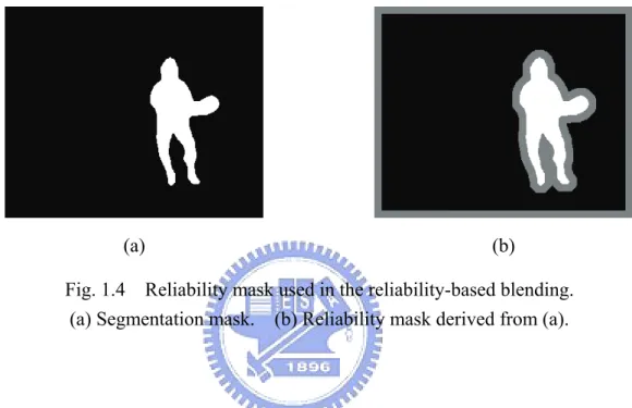
Reliability-based blending is developed to recover the segmentation faults. A
segmentation mask is split into reliable, unreliable and undefined regions to form a reliability
mask. The object pixels in the segmentation mask are defined as undefined region. The
background pixels near an object pixel or the boundary of the frame are defined as unreliable
region. The rest of background pixels are defined as reliable region. Fig. 1.4 shows a
segmentation mask and its reliability mask. The reliable, unreliable and undefined regions are
colored black, gray and white in Fig. 1.4(b), respectively.
Pixels in the undefined region belong to the moving objects, and definitely must not be
blended into a sprite. Pixels in the reliable region are the background pixels, which are safe to
be blended into a sprite. Pixels in the unreliable region are special. They are denoted as
13
faults, background pixels near an object pixel have a higher possibility of being wrongly
classified. Thus these pixels, which belong to the unreliable region, should be treated
carefully.
(a) (b)
Fig. 1.4 Reliability mask used in the reliability-based blending. (a) Segmentation mask. (b) Reliability mask derived from (a).
While blending a pixel into the current sprite, the reliable level is also recorded. The
reliable level of the current pixel is compared to the reliable level of the current sprite. If the
reliable level of the current pixel is lower than the sprite, the current pixel will not be blended
into the sprite and will be discarded. If the reliable levels of both pixels are identical, the
current pixel is blended into the current sprite by averaging blending. If the reliable level of
the current pixel is higher than the sprite, the sprite pixel is discarded and is replaced by the
current pixels. The discard and replace strategy ensures only pixels with highest reliable level
14
1.3.2 Watanabe and Jinzenji’s generator
Watanabe and Jinzenji [34] presented a sprite generator with two-passed blending and
automatic foreground object extraction. In the first pass of sprite blending, a provisional sprite
is constructed using the temporal median. Then the foreground objects are extracted
automatically based on the provisional sprite. A difference image of the current frame from
the provisional sprite is calculated, it is used to classify the pixels of the current frame into
foreground and background ones. Then the current frame is divided into blocks, and each
block is classified as either a foreground one or a background one according to the number of
foreground pixels inside the block. The foreground blocks are excluded in the second pass of
sprite blending. There are two disadvantages. One is that getting a perfect segmentation is
impossible due to that a good threshold is needed in block classification and that block used
as the classification unit will make segmentation roughly. The other is that the additional pass
doubles the blending time.
1.3.3 Lu et al.’s generator
Lu et al. [19-21] used a more precise segmentation method proposed by Meier and Ngan
[36] to obtain moving object masks. Based on the obtained masks, a modified
15
generate sprite. However, the qualities of generated sprites of these methods are still relying
on the precision of segmentation masks.
1.4 Geometric Distortion and Multiple sprites
The performance of a sprite generator is also limited to the perspective motion model
applied in the global motion estimation. The perspective model projects each frame of a video
sequence into a planar reference coordinate system, which is usually the coordinate system of
the first frame. Theoretically, the perspective model employed in MPEG-4 VM can cover 180
degrees of view. However, the useable viewing angle is much smaller in practice, since the
geometric distortion increases rapidly as the camera rotates away from the reference frame.
Fig. 1.5 illustrates the effect of geometric distortion. The focal length of the camera is f
and the reference imaging coordinate system for a sprite is assumed to be the first frame that
is denoted as frame A in Fig. 1.5. All the following frames must be projected to this reference
system by geometric transformation. As the camera rotates, transformed frames are
geometrically distorted, this phenomenon can be found between frame B and transformed
frame B. If camera rotation continues, from Fig. 1.5, we can see that frame C can not be
projected to the reference system.
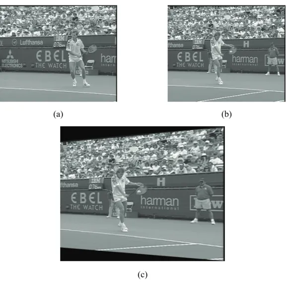
Fig. 1.6 shows a geometric distorted frame. Frame A which shown in Fig. 1.6(a) is
16
the transformed frame B relative to frame A is shown in Fig. 1.6(c). On can see that the
transformed frame B is geometric distorted and its size is larger than the original frames. The
distortion causes the frames away from the reference frame are forced to be recorded by
extremely large resolution, but this resolution is useless because the sprite must be scaled
down to display by the decoder. This useless large resolution increases the memory usage and
storage space required to hold the sprite.
Fig. 1.5 Sprite coordinate system and geometric distortions of transformed frames.
In order to overcome the resolution-increasing effect, Massey and Bender proposed a
method using the middle frame of a video sequence as the reference frame [37]. The
generated sprite will be much symmetric and the boundary area of the generated sprite
becomes much smaller if the background of the frames in the video sequence pans toward
only one direction. On the other hand, this method only slows down the increasing effect of frame A transformed frame B on sprite
frame C
f
sprite coordinate system
camera
frame B
17
the sprite size, but the range of view angle is not extended.
(a) (b)
(c)
Fig. 1.6 Demonstration of geometric distorted frame due to camera rotation. (a) Original frame A. (b) Original frame B. (c) Transformed frame B.
Fig. 1.7 shows two sprites generated from the same portion of sequence ‘stefan’. Fig.
1.7(a) uses the rightmost frame as the reference frame, and Fig. 1.7(b) uses the middle frame
as the reference frame. One can see that the geometric distortion gets worse in the left part of
18
in Fig. 1.7(b) is evenly spread to both left and right part of the sprite. It is obviously that the
sprite using the middle frame as the reference frame is smaller than that using the rightmost
frame.
(a)
(b)
Fig. 1.7 Sprites with different reference frames.
(a) Rightmost frame as reference frame. (b) Middle frame as reference frame.
A technique using multiple sprites was proposed by Farin et al. [38] to solve the problem.
In their works, the background of a scene is stored by multiple sprites. In order to fit the
MPEG-4 standard, a video sequence is divided into several subsequences, and sprites of all
subsequences are generated independently.
19
distortion using only one sprite shown in Fig. 1.5, the geometric distortion of frame B in
sprite #2 becomes smaller. Furthermore, frame C, which is unable to be projected into sprite
#1 can be projected into sprite #2 now. Full 360 degrees of camera view can be covered if
more sprites are used. Note that any single sprite must not cover 90 degree or more of camera
rotation over any direction to prevent an effect called ‘degeneration’ [39].
Fig. 1.8 Geometric distortions using two sprites.
Farin et al. [38] have shown that using multiple sprites not only benefits the wider range
of camera view angles but also reduces storage for the generated sprites. This means that
storage required for multiple sprites is smaller than that for only one sprite. However, the
Farin et al.’s method uses exhaustive searches to find the partition points of sub-sequences
and the reference frame of each sub-sequence. The exhaustive searches make the method very frame A (and transformed A on sprite #1
transformed B on sprite #2
transformed C on sprite #2 reference coordinate of sprite #1
camera
reference coordinate of sprite #2
frame C frame B
20
time-consuming.
Some sprite generators are proposed to employ the multiple sprite technique. Chen et. al.
intergrates a frame skipping techniques and the multiple sprite to speed up the overall
computation time of sprite generation [40-41]. Kunter et al. proposed a experimental
framework [42] to employ multiple sprite into H.264/AVC. None of them is discussing to
speed up the multiple sprite partition.
1.5 Farin et al.’s Optimal Partition Algorithm
In order to find the optimal partition of a video sequence, an evaluation of partition
results must be selected. In order to reduce the computational complexity, the area of the
bounding box around a sprite is chosen to be the evaluation cost function in Farin et al.’s
work. Their optimal partition algorithm is divided into two steps. The first step computes the
minimal costs for coding sprites of all possible sub-sequences and finds the optimal reference
frames of every possible sub-sequence. The second step decides the optimal partition
positions which minimize the coding costs computed in the first step. In the following, we
will give a brief review for their optimal partition algorithm.
1.5.1 Coding Costs Computing and Reference Frames Finding
21
sub-sequences are computed in this step. For a sub-sequence beginning at frame i and ending
at frame k, a sprite r k i
S; can be generated for a reference frame r with i≤r≤k. The coding cost for coding r
k i S; is denoted as r k i S; . r k i
S; of all possible combination of i, k, and r are
computed. The number of possible combinations is huge and this computation will take a lot
of time. After computing all r k i
S; , the optimal reference frame * ;k
i
r of a sub-sequence
beginning at frame i and ending at frame k can be selected by
r k i r k i S r* ; ; =argmin . (1.9)
The minimized coding cost of this sub-sequence, r k i r k
i S
S; =min ; , is also kept.
The optimal reference frames for every possible sub-sequences are found and stored in
upper triangular matrixes indexed by i and k.
1.5.2 Optimal Partitioning
In order to obtain the optimal partition, not only the starting frame (partition position) of
each sub-sequence but also the number of sub-sequences must be decided. If the video is
partitioned into n sub-sequences, n-1 starting frames need to be decided since the first
sub-sequence always starts at frame 1. For a video with N frames, a partition for the video can
be represented by
)}P={(1,p1−1),(p1,p2−1),(p2,p3−1),...,(pn−1,N , (1.10) where pi is the starting frame of sub-sequence i+1. The sprite coding cost of a video sequence
22
using a partition P is the summation of sprite coding costs of all partitioned sub-sequences,
and the optimal partition P* is selected as
∑
∈ = P k i ik P S P ) , ( ; * argmin . (1.11)The minimization problem is solved efficiently. If the video contains only the first frame,
there is only 1 possible partition P={(1,1)} and the optimal sprite coding cost of the video is 1
; 1
S which is denoted as c1. If the video contains more than one frame, the remaining frames
are then added one by one. When adding frame k, the optimal sprite coding cost ck for the
sequence ending at frame k can be calculated as
{
}
{
}
, min arg min ; 1 ] , 1 [ ; 1 ] , 1 [ k i i k i k k i i k i k S c p S c c + = + = − ∈ − ∈ (1.12)where c0 is set to zero. The frame pk is the best partition point to obtain the minimal cost for
each frame k.
After calculating cN which is the minimal sprite coding cost for the entire sequence, the
optimal partition can be obtained by back tracking the stored p-values from pN. That is, the
entire sequence is best partitioned at frame pN to form two sub-sequences (1,pN −1) and
) ,
(pN N . The former sub-sequence is further divided at ( −1)
N
p
p , which is the best partition
point of sub-sequence (1,pN −1), and so on.
23
The main problems that this dissertation tries to address are based on the
above-mentioned segmentation masks related problems and the time complexity problem of
multiple sprites generating. These will be described in the following.
In this dissertation, we will propose methods to deal with the problems of single and
multiple sprite generation. For the traditional single sprite generation, a new generation
method without using segmentation masks will be proposed to avoid the segmentation faults
from affecting the generated sprite. For the multiple sprite generation, a fast generation
method will be proposed to increase the search speed of sub-sequences and selecting of
reference frames.
1.6.1 Sprite Generation without Segmentation Masks
The framework of MPEG-4 VM shown in Fig. 1.1 requires segmentation masks while
generating sprites. Segmentation masks are binary maps indicating whether a pixel belongs to
moving objects or not. In order to avoid sprite being blurred, pixels of moving objects must be
excluded from being blended into the sprite. If the segmentation is perfect, the averaging
blending provided in MPEG-4 can achieve excellent quality; otherwise, the generated sprite
will be blurred around moving object boundary due to that some pixels of moving objects are
considered as background.
24
generating automatically during the sprite generation process. No matter how the
segmentation masks are provided, they must be generated automatically to makes the sprite
generation practical. However, it is almost impossible to generate segmentation masks
perfectly automatically. Thus segmentation faults always exist, and the generated sprite
always looks blurry.
On the purpose of reducing the blur caused by segmentation faults, precise segmentation
methods [36] are employed [34] and a new blending strategy denoted as reliability-based
blending [18] is developed. The reliability-based blending is adopted by several sprite
generators [18-21]. In the reliability-based blending strategy, a frame is divided into reliable,
unreliable, and undefined regions according to the segmented masks. Pixels denoted as
objects in the segmented masks are classified as undefined pixels, and pixels near mask
borders or frame borders (within a given distance) are classified as unreliable ones. The rest
of pixels are classified as reliable ones. The reliable and unreliable pixels are average-blended
separately, and the blended pixels with the highest reliability are chosen into the sprite. The
undefined pixels do not contribute to the sprite blending. The given distance from the mask
border must be large enough to cover all segmentation faults, or the generated sprite will have
ghost-like shadows in some places. However, it is hard to decide the distance automatically.
Thus ghost-like shadows still can be found in the generated sprite. In order to overcome this
25
segmentation masks.
Segmentation masks are not only used in the blending process, but also in the global
motion estimation process. The global motion estimation uses segmentation masks to avoid
objects affecting the accuracy of generated global motion parameters. For removing the usage
of segmentation masks completely from the entire sprite generation process, the global motion
estimation must also be modified.
1.6.2 Fast Multiple Sprites Generation
The perspective model employed in the global motion estimation process makes the
transformed frames geometric distorted, as Fig. 1.6 shows. This distortion become more
seriously as the camera view of frame away from the reference frame. Frames away from the
reference frame are forced to be recorded by extremely large resolution, but this resolution is
useless because the sprite must be scaled down to display by the decoder.
Massey and Bender proposed to use the middle frame of a video sequence as the
reference frame to overcome the resolution-increasing effect. The generated sprite will be
much symmetric and the boundary area of the generated sprite becomes much smaller if the
background of the frames in the video sequence pans toward only one direction. However,
this method only slows down the increasing effect of the sprite size, but the range of view
26
Using multiple sprites can solve this problem. Before generating multiple sprites, a video
sequence must be divided into several subsequences. Each frame in the video sequence can be
a partition position from which the video sequence is divided into subsequences. Thus, a
partition algorithm is needed. For a video sequence with N frames, there will be 2N-1 combinations of partitions. Not only the partition position but also the reference frame of each
subsequence must be selected by the partition algorithm. The selection of reference frames
greatly affects the size of generation sprites. Each frame in a subsequence can be selected as
the reference frame of the subsequence. If the sequence is divided into K subsequences, each
subsequence has Mi frames, where i is the index of a subsequence. There will be
∏
= K i i M 1 selections for reference frames. Farin et al. proposed an optimal multiple sprite partition
algorithm. A cost function representing the total area of all generated sprites was defined, and
a smart exhaustive search through the entire partition positions and reference frame
possibilities was proposed. Since the partition algorithm is an exhaustive search, it finds the
optimal solution. However, it is very time-consuming.
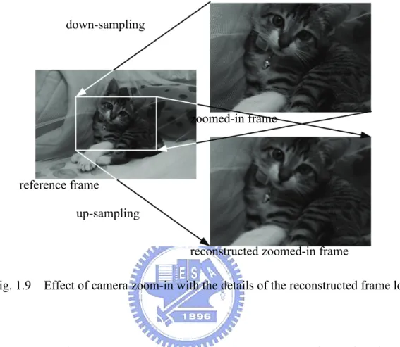
Apart from the geometric distortion, the effect of camera zoom-in and zoom-out will
highly affect the generated sprite and the reconstructed frames [38]. Fig. 1.9 illustrates how
camera zoom-in operation affects generated sprite and reconstructed frame. Since the
reference coordinate system is based on the reference frame, the zoomed-in frame has to be
27
forever during the down-sampling and the reconstructed frame is degraded.
Fig. 1.9 Effect of camera zoom-in with the details of the reconstructed frame lost.
In contrast to the camera zoom-in, the camera zoom-out operation makes the generated
sprite looks blur after the zoomed-out frame is blended into the sprite. As Fig. 1.10 shows, the
zoomed-out frame has to be up-sampled before blending into the sprite. This will make the
blended sprite blurred. Furthermore, the up-sampled frame will occupy a very large area in
the sprite. This causes the area of generated sprite being expanded rapidly.
In this dissertation, we try to develop a fast multiple sprites partition method and fast
reference frame selection method with acceptable total sprite areas. zoomed-in frame
reconstructed zoomed-in frame reference frame
down-sampling
28
Fig. 1.10 Effect of camera zoom-out with the sprite blurred.
1.7 Synopsis of the Dissertation
The rest of the dissertation is organized as follows. Chapter 2 describes the proposed
sprite generation method with automatically generated segmentation masks. In Chapter 3, the
proposed sprite generation method without using segmentation masks will be introduced. The
fast multiple sprite partition and reference frame selection methods are proposed in Chapter 4.
Some conclusions and future research directions are drawn in Chapter 5.
zoomed-out frame
reference frame
29
CHAPTER 2
AUTOMATIC GENERATION OF SEGMENTATION MASKS
FOR SPRITE GENERATION
In this chapter, we will propose a sprite generator with an automatic generation of
segmentation masks. The generation process contains two passes. The first pass generates a
coarse sprite by conventional averaging blending method. Then we generate segmentation
masks of every frame automatically from the coarse sprite. In the second pass of sprite
generation, the final sprite is generated with the generated segmentation masks to reduce the
effect of moving objects. The details of the proposed generator are described as follows.
2.1 Proposed Two-Pass Sprite Generation
As Fig. 1.1 shows, MPEG-4’s sprite generation framework requires auxiliary
segmentation masks to reduce the effect of moving objects. Segmentation masks are used in
global motion estimation to raise the estimation accuracy. These masks can also be used to
avoid moving objects attending the sprite blending. It is impractical to build these masks
manually. Thus an automatic generation of segmentation masks is necessary. Since the sprite
is a merged background in the video sequence, it can be used as a reference background for
30
2.1.1 Object blurring effect of averaging blending
The averaging blending used in sprite generation has a blurring effect to every pixel in
the sprite. If there does not have segmentation masks, the averaging blending blends pixels of
moving objects and background together. In case of enough frames are blended, the moving
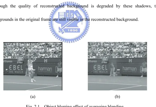
objects will be blurred and only shadows of objects are left in a generated sprite. Fig. 2.1
demonstrates the blurring of moving objects. Figs. 2.1(a) and (b) are an original frame and its
reconstructed background from generated sprite, respectively. One can see that the moving
player is blended into the sprite, and leave white shadows in the reconstructed background.
Although the quality of reconstructed background is degraded by these shadows, the
backgrounds in the original frame are still visible in the reconstructed background.
(a) (b)
Fig. 2.1 Object blurring effect of averaging blending. (a) Original frame. (b) Reconstructed background of (a).
31
2.1.2 Frame segmentation in sprite generation
Since reconstructed backgrounds in a sprite generated by averaging blending without
segmentation masks are only blurred by moving objects, the reconstructed backgrounds can
be used as reference backgrounds to detect moving objects. A two-pass sprite generation with
automatic segmentation masks generation is proposed and shown in Fig. 2.2.
Fig. 2.2 The proposed two-pass sprite generator.
In the first pass of the proposed generator, a coarse sprite is generated first by the
MPEG-4’s sprite generator without segmentation masks. The coarse sprite will contain
shadows of moving objects definitely. Then the reconstructed backgrounds of the coarse sprite
32
segmentation masks automatically. Finally the sprite is re-generated in the second pass by the
MPEG-4’s sprite generator with the generated segmentation masks.
2.2 The First Pass of Sprite Generation
The first pass of sprite generation is almost identical to the MPEG-4’s framework. In the
global motion estimation, some feature points are extracted by selecting the pixels with larger
Hessian value. Then global motion parameters are estimated by a least mean-square-error
minimization method, the Levenberg-Marquardt algorithm. An averaging blending method is
employed as the blending method. No segmentation masks are applied in this pass of sprite
generation. Thus moving objects will be blended and the generated coarse sprite will be
blurred. The coarse sprite will be used to extract the segmentation masks automatically.
2.3 Automatic Generation of Segmentation Masks
Despite of the blurred areas, the reconstructed backgrounds still carry most of
background information. By subtracting the original frame by the reconstructed background,
we can get an image of the moving objects. In order to remove the effect of peak noise, the
block difference is applied instead of the pixel difference.
The pixel difference D is defined as the magnitude of the difference between the original
33
the candidates of object pixels. Pixels with D value larger than t1 are considered as candidates.
For each candidate, a 5×5 block B centered on the candidate is taken. The block difference DB,
is defined as
∑
∈ = B j i B D i j D ) , ( ) , ( . (2.1)The candidate with block difference larger than a preset threshold t2 is considered as an object
pixel. The two-stage thresholding technique computes the block differences only for those
pixels with higher possibility to be objects. It reduces the complexity of computing block
difference for each pixel.
There are two problems while extracting the object pixels. First, the object regions are
often ill-shaped with holes. Second, there are some small-sized regions which are
misclassified as objects. These problems can be solved using morphological processing and
region selecting. Let O be a binary image representing the results of thresholding in the
previous step. Pixels judged as objects will be set to one and others will be set to zero. Two
binary images called seed and base images are computed. The seed image is produced by
applying morphological erosion to O using a disk shaped structure element of radius 2, and
the base image is produced by applying morphological dilation to O using the same shaped
structure element of radius 5. The region selecting is applied on the base image. An object
region is selected if any of its pixels have a value of one in the seed image. The segmentation
34
Fig. 2.3 gives an example of generating a segmentation mask. The original frame and the
reconstructed background of the frame are shown in Figs. 2.3(a) and (b) respectively. By
subtracting the original frame by the reconstructed background and performing the two-stage
thresholding, the image of the extracted object pixels is shown in Fig. 2.3(c). The seed image
shown in Fig. 2.3(d) and the base image shown in Fig. 2.3(e) are generated by applying the
morphological processing to Fig. 2.3(c). Finally, the segmentation mask is produced by
region selecting and shown in Fig. 2.3(f). The object regions are colored black.
(a) (b)
(c) (d)
Fig. 2.3 (Continued) The generation of a segmentation mask. (a) The original image. (b) The reconstructed background. (c) The object pixels extracted by using two-stage
thresholding. (d) The seed image. (e) The base image. (f) The generated segmentation mask.
35
(e) (f)
Fig. 2.3 The generation of a segmentation mask. (a) The original image. (b) The reconstructed background. (c) The object pixels extracted by using two-stage
thresholding. (d) The seed image. (e) The base image. (f) The generated segmentation mask.
Most part of the moving objects was extracted correctly, except two unclassified parts:
the upper part of bat and the player’s legs. The upper part of bat is nearly transparent hence
the background is visible through the bat; the legs of the player have similar intensities to the
background. Thus, both misclassified parts do not affect the blending result. Moreover, the top
and right borders are also classified as object; this will eliminate the black line shadows in the
generated sprite. Note that the tennis ball is also classified as an object. These generated
segmentation masks will be employed in the second pass of sprite generation.
2.4 The Second Pass of Sprite Generation
The generated segmentation masks are employed in the second pass of sprite generation.
36
automatically generated segmentation masks are employed in the global motion estimation
and the blending process. These modifications remove the effect caused by considering the
object pixels as background, and increase the fidelity of the generated sprite.
In the global motion estimation, the generated segmentation masks are employed as a
classification of object pixels. All feature points are checked with the masks. Feature points
which are classified as moving objects in the masks are removed from the feature points.
Then the global motion parameters are also estimated by the Levenberg-Marquardt algorithm.
The accuracy of estimated parameters should be increased since the effect of object pixels is
reduced.
The sprite is then blended using the newly estimated parameters. Since generated
segmentation masks are available in the second pass, the reliability-based blending is adopted
instead of the averaging blending employed in the first pass. The reliability-based blending
prevents some of moving objects that not segmented correctly from being blended into the
final sprite. The generated sprite in the second pass is outputted as the final sprite.
2.5 Experimental Results
Fig. 2.4 shows the generated sprite of the video sequence ‘stefan’ by different methods.
Fig. 2.4(a) is generated by the MPEG-4’s method without using segmentation masks, that is
37
generate Fig. 2.4(b) are obtained automatically by the proposed segmentation schema.
Fig. 2.5 shows one of the reconstructed frames by different methods respectively. Like
we stated before, the sprite generated without using masks contains shadows, which are
circled in Fig. 2.4(a), caused by wrongly blending the player into sprite. These shadows are
successfully removed in the sprite generated using the masks generated automatically by our
method. Manually segmented masks are employed in Fig. 2.4(c) and Fig. 2.5(c) for
comparisons. Both sprites generated using automatically or manually segmented masks are
perceptually the same by human eyes.
(a)
Fig. 2.4 (Continued) Generated sprites of different methods. (a) The first pass. (b) Two pass generation with automatic generated segmentation masks.