國立交通大學
電子工程學系 電子研究所
碩 士 論 文
基於記憶體式乘法器並實現於可程式邏輯閘陣列之
高速且面積最小化的有限脈衝響應濾波器設計
High-Speed and Area-Minimized FIR Filter Design
using Memory-Based Multiplication on FPGAs
研 究 生 : 許晉維
指導教授 : 黃俊達 博士
基於記憶體式乘法器並實現於可程式邏輯閘陣列之
高速且面積最小化的有限脈衝響應濾波器設計
High-Speed and Area-Minimized FIR Filter Design
using Memory-Based Multiplication on FPGAs
研究生 : 許晉維
Student: Jin-Wei Hsu
指導教授 : 黃俊達 博士
Advisor: Dr. Juinn-Dar Huang
國立交通大學
電子工程學系 電子研究所
碩士論文
A Thesis
Submitted to Department of Electronics Engineering & Institute of Electronics College of Electrical & Computer Engineering
National Chiao Tung University in Partial Fulfillment of the Requirements
for the Degree of Master of Science
in
Electronics Engineering & Institute of Electronics December 2012
Hsinchu, Taiwan, Republic of China 中華民國一0一年十二月
i
基於記憶體式乘法器並實現於可程式邏輯閘陣列之
高速且面積最小化的有限脈衝響應濾波器設計
研究生 : 許晉維
指導教授 : 黃俊達 博士
國立交通大學
電子工程學系 電子研究所碩士班
摘 要
在有限脈衝響應濾波器中最複雜的部份為多重常數乘法器(MCM)區塊,它將一筆 資料乘上多個常數係數。而多重常數乘法器區塊中的乘法器可利用基於記憶體架構的 乘法器來取代,因此為了減少記憶體大小有許多方法被提出來。在此篇論文中,我們 提出一個以整數線性規劃(ILP)為基礎的方法,藉由尋找最少數目的共用部份乘積來實 現所有的常數乘法,最小化多重常數乘法器區塊面積,並將其運用於現場可程式化邏 輯閘陣列。由實驗結果可知,我們的方法和文獻上所知最先進的作法相比,以平均值 而言,減少了超過 10%的延遲和 50%的面積,且當常數係數個數增加時記憶體大小減 少的幅度更為明顯。ii
High-Speed and Area-Minimized FIR Filter Design
using Memory-Based Multiplication on FPGAs
Student: Jin-Wei Hsu
Advisor: Dr. Juinn-Dar Huang
Department of Electronics Engineering & Institute of Electronics
National Chiao Tung University
Abstract
The complexity of finite impulse response (FIR) filters is dominated by multiple constant multiplication (MCM) block which realizes the multiplication of one data sample with multiple constant coefficients. Many works have been proposed for minimizing memory size since multiplications in an MCM block can be implemented by memory-based multipliers. In this work, we present an integer linear programming (ILP) based approach to minimize the area of MCM block implemented on the field programmable gate array (FPGA) by finding the minimal number of common partial products to carry out all constant multiplications. Experimental results show that on average, compared with an existing state-of-the-art method, the proposed method reduces delay and area by more than 10% and 50%, respectively. Moreover, the reduction of memory size is more prominent when the number of constant coefficients increases.
iii
Acknowledgement
首先我要衷心感謝指導教授,黃俊達博士,感謝老師在研究期間所給予的指導, 老師總是用最嚴謹的態度指導我做研究並提供許多寶貴的意見與想法,讓我面對問題 時能有獨立思考且解決問題的能力,不僅在學業及研究方面的指導,在待人處事的道 理上也讓我受益良多。接著要感謝我的口試委員們,周景揚教授和張世杰教授,百忙 之中抽空前來指導我,讓我得到寶貴的經驗,非常感謝。 再來要感謝我的家人及女友,感謝你們在我遇到挫折時給予我安慰與支持,陪伴 我度過這些日子,以及口試前給我加油打氣幫我消除緊張,謝謝你們。 我也要感謝實驗室的學長姐,感謝你們的幫忙,尤其是陳詣航學長,感謝學長費 心協助我完成研究與論文。還有我的同學,賴鵬先、劉廣正、陳怡廷和謝明廷,很開 心能跟你們一起修課與討論,讓我有了一段值得珍惜的回憶。最後謝謝一起準備口試 的惠珊以及幫忙打理一切的建宇跟偉豪。iv
Contents
摘 要 ... i Abstract ... ii Acknowledgement ... iii Contents ... iv List of Tables ... v List of Figures ... vi Chapter 1 Introduction ... 11.1 Finite Impulse Response Filters ... 1
1.2 Conventional Memory-Based Multiplier... 1
1.3 Field Programmable Gate Array ... 3
1.4 Thesis Organization ... 4 Chapter 2 Background ... 5 2.1 Previous Works ... 5 2.2 Terminology ... 9 Chapter 3 Motivation ... 11 3.1 Motivational Example ... 11 3.2 Problem Formulation ... 13
Chapter 4 Proposed Algorithm ... 14
4.1 Proposed Architecture... 14
4.2 Definitions ... 15
4.3 Overall Flow ... 17
4.4 Coefficient Assembly Tree Construction ... 18
4.5 Tree Pruning ... 21
4.6 ILP Formulation... 23
Chapter 5 Experimental Results ... 29
5.1 Experimental Environment ... 29
5.2 Experimental Results for Different Width ... 30
5.3 Experimental Results for Different D ... 32
Chapter 6 Conclusion ... 35
v
List of Tables
Table 1. OMS example for input word length L = 4. ... 6
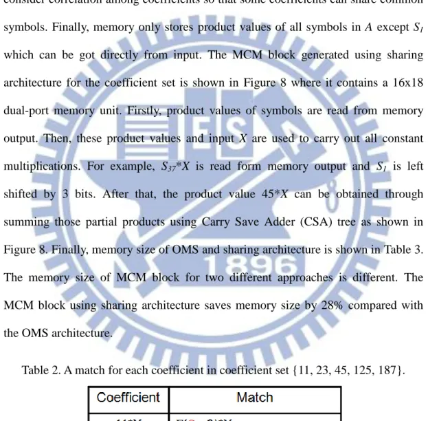
Table 2. A match for each coefficient in coefficient set {11, 23, 45, 125, 187}. ... 12
Table 3. Memory size of OMS and sharing architecture for 8 bits input. ... 13
Table 4. Maximum numbers of supports of CSA tree. ... 17
Table 5. Area cost for different numbers of supports. ... 26
Table 6. FIR filters with14-bit coefficient word length. ... 30
Table 7. FIR filters with 16-bit coefficient word length. ... 30
Table 8. Results for width=14... 32
vi
List of Figures
Figure 1. An N-tap Transposed FIR filter. ... 1
Figure 2. (a) Memory-based multiplier example. (b) Using memory partition example. ... 3
Figure 3. The amount of FPGA resources of the Altera Stratix family. ... 4
Figure 4. (a) OMS architecture. (b) Address encoder circuit. (c) Control circuit. ... 7
Figure 5. OMS architecture using dual-port memory. ... 8
Figure 6. An N-tap FIR filter using OMS architecture. ... 9
Figure 7. MCM block using OMS architecture for coefficient set {11, 23, 45, 125, 187}. ... 11
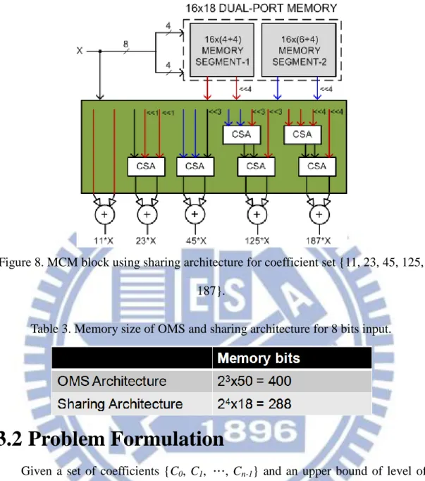
Figure 8. MCM block using sharing architecture for coefficient set {11, 23, 45, 125, 187}. .. 13
Figure 9. Proposed MCM block architecture. ... 14
Figure 10. A CAT for a coefficient C=4’b1011. ... 15
Figure 11. (a) Example of support number of Path0,3. (b) Example of support number of Path0,9. ... 16
Figure 12. The overall flow of proposed algorithm. ... 18
Figure 13. A CAT(01011) example to illustrate the function CAT. ... 20
Figure 14. An example to illustrate the sub-function Sym_Enum when num_1=1. ... 21
Figure 15. An example to illustrate the function PCAT. ... 23
Figure 16. An example of combining two LUTs into a 32x1 bit memory. ... 26
Figure 17. ILP results for coefficient set {1011, 10111}. ... 28
Figure 18. Results of memory bits for different D. ... 33
Figure 19. Results of LUTs for different D. ... 34
1
Chapter 1
Introduction
1.1 Finite Impulse Response Filters
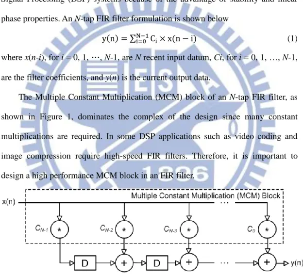
Finite Impulse Response (FIR) digital filters are widely used in many Digital Signal Processing (DSP) systems because of the advantage of stability and linear phase properties. An N-tap FIR filter formulation is shown below
(1) where x(n-i), for i = 0, 1, …, N-1, are N recent input datum, Ci, for i = 0, 1, …, N-1, are the filter coefficients, and y(n) is the current output data.
The Multiple Constant Multiplication (MCM) block of an N-tap FIR filter, as shown in Figure 1, dominates the complex of the design since many constant multiplications are required. In some DSP applications such as video coding and image compression require high-speed FIR filters. Therefore, it is important to design a high performance MCM block in an FIR filter.
Figure 1. An N-tap Transposed FIR filter.
1.2 Conventional Memory-Based Multiplier
The MCM block contains a large number of constant multiplications while multiplier is a highly time-consuming unit. The general-purpose multipliers in an
2
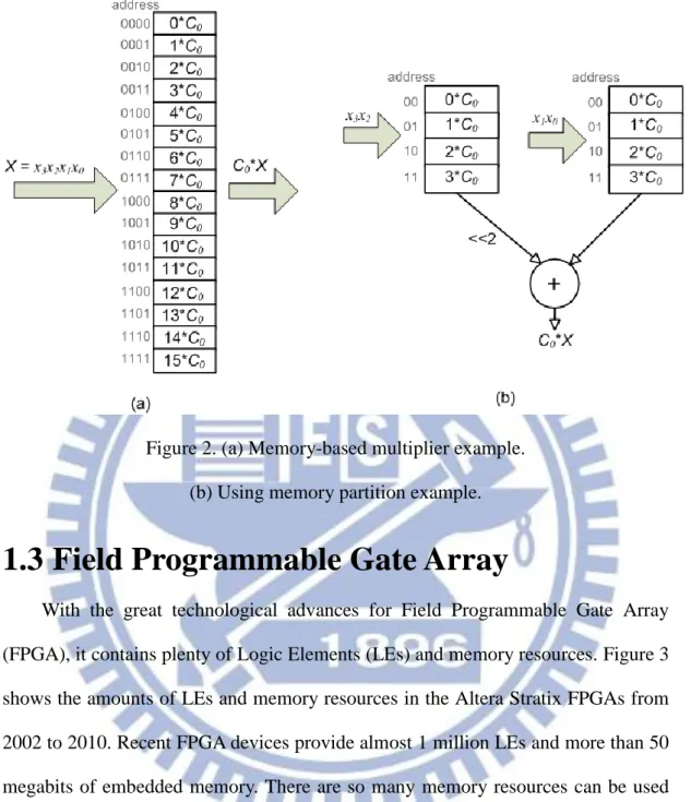
MCM block can be replaced by conventional memory-based multipliers since the constant coefficients of an FIR filter can be obtained beforehand. A conventional memory-based multiplier example is depicted in Figure 2(a). Assume C0 is a
constant coefficient and X is a 4-bit input word to be multiplied with C0. There are 24
possible product values C0*X because X has 24 possible values. Thus, the
memory-based multiplier is composed of a memory unit of 24 words which stores all possible pre-computed product values corresponding to all possible values of input
X. If the input X is used as address of the memory unit and then the corresponding
product value can be read from the memory unit.
Memory-based multiplier is a high-speed constant multiplier but the memory size will increase exponentially with the word-length of input value. In order to reduce memory size, the scheme called memory partition was proposed in [1] where a conventional memory-based multiplier can be implemented by two smaller memory units and one adder. Figure 2(b) shows a memory unit of 24 words is replaced by two memory units of 22 words and one adder to sum the partial results from two memory units. The left-shifter in Figure 2(b) is easily performed by using wire permutations without additional cost. For instance, total memory bits in Figure 2(a) are 144 bits while total memory bits in Figure 2(b) are 56 bits. Although the memory partition scheme needs an additional adder component, it can greatly reduce the memory size especially when the word-length of input value is long.
3
Figure 2. (a) Memory-based multiplier example. (b) Using memory partition example.
1.3 Field Programmable Gate Array
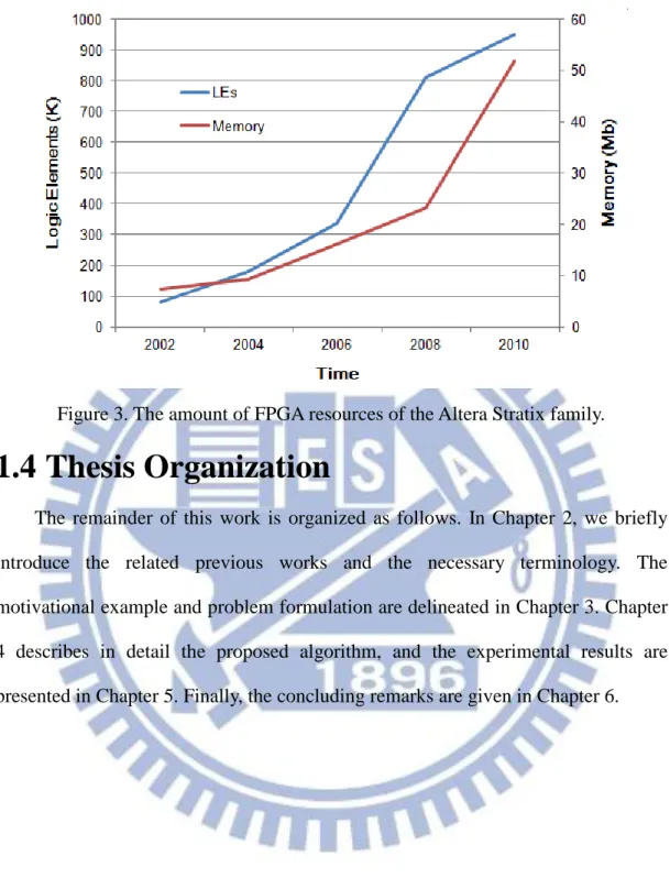
With the great technological advances for Field Programmable Gate Array (FPGA), it contains plenty of Logic Elements (LEs) and memory resources. Figure 3 shows the amounts of LEs and memory resources in the Altera Stratix FPGAs from 2002 to 2010. Recent FPGA devices provide almost 1 million LEs and more than 50 megabits of embedded memory. There are so many memory resources can be used in FPGA devices that FIR filters using memory-based multiplier are very suitable to be implemented on FPGAs.
4
Figure 3. The amount of FPGA resources of the Altera Stratix family.
1.4 Thesis Organization
The remainder of this work is organized as follows. In Chapter 2, we briefly introduce the related previous works and the necessary terminology. The motivational example and problem formulation are delineated in Chapter 3. Chapter 4 describes in detail the proposed algorithm, and the experimental results are presented in Chapter 5. Finally, the concluding remarks are given in Chapter 6.
5
Chapter 2
Background
In this chapter, we briefly introduce the related previous works which are proposed to reduce memory size of memory-base multiplier in Section 2.1. Then, the terminology is presented in Section 2.2.
2.1 Previous Works
In an early paper, [1] proposed the memory partition scheme, which replaces one memory unit with two smaller memory units and one adder, to save memory size of memory-based multiplier. Next, different approaches for memory-based multiplication have been studied [2]–[18]. In [8] aimed to single constant multiplication on FPGA. The method is to split the input into several segments and then use 4-bit Look-Up Tables (LUTs) to generate the partial products of coefficient multiplication. It also noted three kinds of LUTs are redundant. First, LUT contains all zeroes or ones, which can be replaced with a constant signal value. Second, the contents of the LUTs are identical, which can be replaced with a single LUT. Third, the output of LUT is the same with one of address bits, which can easily use wire to replace. After removing all redundant LUTs, the partial products are added by Carry Propagate Adders (CPAs). Then, [9] extended this method to multiple constant multiplications. However, it is limited that through removing the redundant LUTs to reduce memory size.
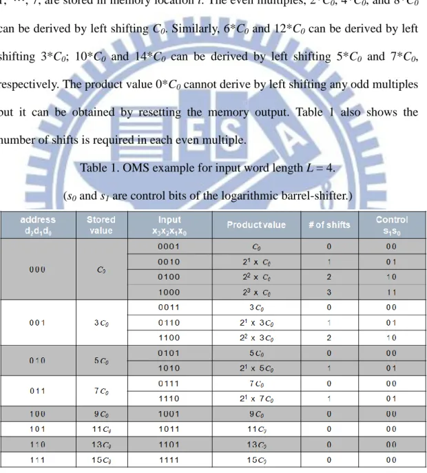
An approach to improve memory-based multiplication, called Odd-Multiple-Storage (OMS), was proposed in [17], where the memory size is saved by half. In conventional memory-based multiplier, the memory consists of 2L
6
possible product values C0*X corresponding to all possible values of X with
word-length L while [17] said the memory only stores (2L/2) words corresponding to the odd multiples of C0. The others are even multiples of C0 which can be derived by
left shifting one of the odd multiples of C0 except the product word is zero. An
example for L = 4 is illustrated in Table 1. The product values C0*(2i+1), for i = 0,
1, …, 7, are stored in memory location i. The even multiples, 2*C0, 4*C0, and 8*C0
can be derived by left shifting C0. Similarly, 6*C0 and 12*C0 can be derived by left
shifting 3*C0; 10*C0 and 14*C0 can be derived by left shifting 5*C0 and 7*C0,
respectively. The product value 0*C0 cannot derive by left shifting any odd multiples
but it can be obtained by resetting the memory output. Table 1 also shows the number of shifts is required in each even multiple.
Table 1. OMS example for input word length L = 4. (s0 and s1 are control bits of the logarithmic barrel-shifter.)
7
(a)
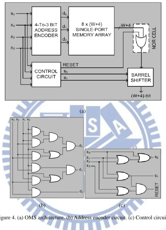
(b) (c)
Figure 4. (a) OMS architecture. (b) Address encoder circuit. (c) Control circuit. The OMS architecture for multiplication of W-bit constant coefficient with 4-bit input operand is depicted in Fig 4. The area of address encoder and control circuit are small while the area of barrel shifter will linearly increase with increasing bit-width of product value. Although it can save memory size by half, it also increases extra delay and area because of address encoder, control circuit, NOR cell, and barrel shifter.
8
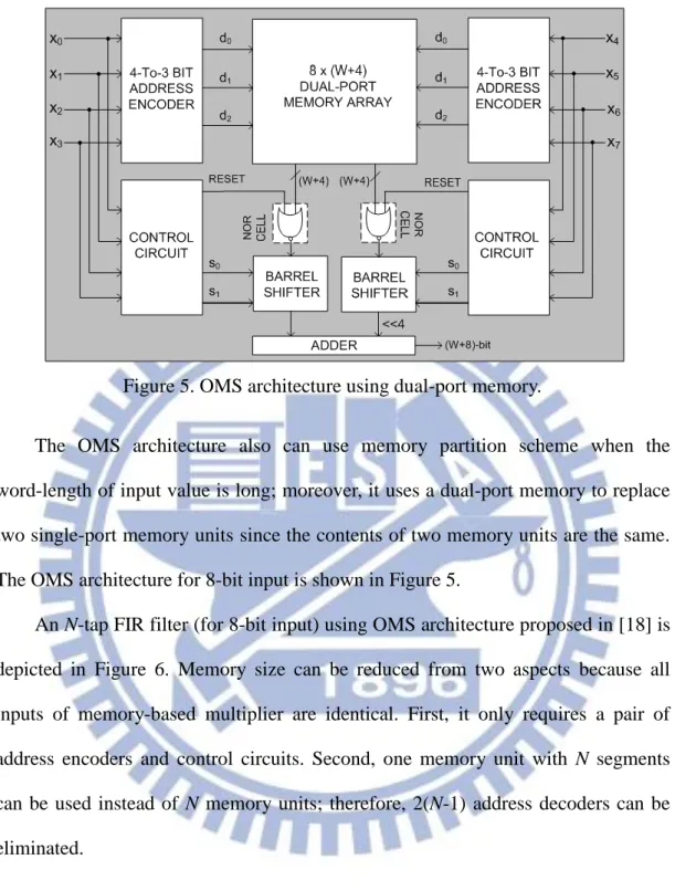
Figure 5. OMS architecture using dual-port memory.
The OMS architecture also can use memory partition scheme when the word-length of input value is long; moreover, it uses a dual-port memory to replace two single-port memory units since the contents of two memory units are the same. The OMS architecture for 8-bit input is shown in Figure 5.
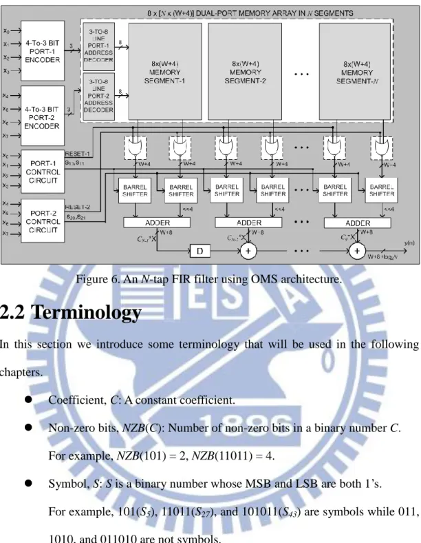
An N-tap FIR filter (for 8-bit input) using OMS architecture proposed in [18] is depicted in Figure 6. Memory size can be reduced from two aspects because all inputs of memory-based multiplier are identical. First, it only requires a pair of address encoders and control circuits. Second, one memory unit with N segments can be used instead of N memory units; therefore, 2(N-1) address decoders can be eliminated.
9
Figure 6. An N-tap FIR filter using OMS architecture.
2.2 Terminology
In this section we introduce some terminology that will be used in the following chapters.
Coefficient, C: A constant coefficient.
Non-zero bits, NZB(C): Number of non-zero bits in a binary number C. For example, NZB(101) = 2, NZB(11011) = 4.
Symbol, S: S is a binary number whose MSB and LSB are both 1’s.
For example, 101(S5), 11011(S27), and 101011(S43) are symbols while 011,
1010, and 011010 are not symbols.
Alphabet, A: A is a set of symbols. For example, A = {S5, S27, S43}.
Fragment, F(S, i): A number generated from left shifting S by i bits. For example, F(S11, 3) = 1011 << 3 = 1011000.
Match, M: A match for a coefficient C with respect to alphabet A is a set of fragments such that and .
10
For example, assume A = {S1, S3, S13, S19, S51} and C = 110110.
Coefficient C has three kinds of matches, namely M0 = {F(S3, 4), F(S3, 1)},
M1 = {F(S13, 2), F(S1, 1)}, and M2 = {F(S19, 1), F(S1, 4)}. Although F(S51,
0) plus F(S3, 0) equals C, {F(S51, 0), F(S3, 0)} is not a match since
11
Chapter 3
Motivation
In this chapter, we show a motivational example to demonstrate memory size of memory-base multiplier can further reduce by using sharing architecture which shares common symbols among coefficients. Then, we present the problem formulation of this work.
3.1 Motivational Example
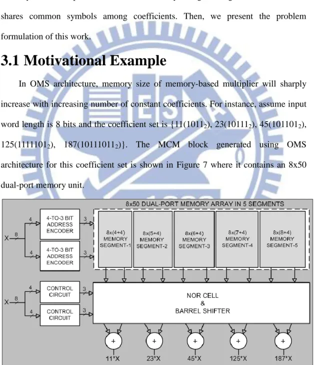
In OMS architecture, memory size of memory-based multiplier will sharply increase with increasing number of constant coefficients. For instance, assume input word length is 8 bits and the coefficient set is {11(10112), 23(101112), 45(1011012),
125(11111012), 187(101110112)}. The MCM block generated using OMS
architecture for this coefficient set is shown in Figure 7 where it contains an 8x50 dual-port memory unit.
Figure 7. MCM block using OMS architecture for coefficient set {11, 23, 45, 125, 187}.
12
The MCM block generated using OMS architecture can save memory size by half while OMS architecture does not consider correlation among different coefficients. We assume the alphabet set A={1(S1), 1011(S11), 100101(S37)}; a match
for each coefficient in coefficient set {11, 23, 45, 125, 187} is shown in Table 2. The symbols in A can use left shifting and adders to derive all coefficients because we consider correlation among coefficients so that some coefficients can share common symbols. Finally, memory only stores product values of all symbols in A except S1
which can be got directly from input. The MCM block generated using sharing architecture for the coefficient set is shown in Figure 8 where it contains a 16x18 dual-port memory unit. Firstly, product values of symbols are read from memory output. Then, these product values and input X are used to carry out all constant multiplications. For example, S37*X is read form memory output and S1 is left
shifted by 3 bits. After that, the product value 45*X can be obtained through summing those partial products using Carry Save Adder (CSA) tree as shown in Figure 8. Finally, memory size of OMS and sharing architecture is shown in Table 3. The memory size of MCM block for two different approaches is different. The MCM block using sharing architecture saves memory size by 28% compared with the OMS architecture.
13
Figure 8. MCM block using sharing architecture for coefficient set {11, 23, 45, 125, 187}.
Table 3. Memory size of OMS and sharing architecture for 8 bits input.
3.2 Problem Formulation
Given a set of coefficients {C0, C1, …, Cn-1} and an upper bound of level of
CSA tree D. The given D is used to constrain timing of MCM block. The objective of this work is to decide a match for each coefficient and determine an alphabet that lead to minimum total area cost of MCM block.
14
Chapter 4
Proposed Algorithm
Our proposed algorithm, called Global Optimal Symbol Match (GOSM), is described in this chapter. Firstly, we introduce proposed architecture and definitions which are used in GOSM in Section 4.1 and 4.2 respectively; then, flow chart of GOSM is illustrated in Section 4.3. GOSM consists of two main parts which are explicitly described in Section 4.4 and Section 4.5, respectively.
4.1 Proposed Architecture
A two-stage MCM block using memory-based multiplication is depicted in Figure 9. The first stage generates the product values of common symbols and then they are used to realize all constant multiplications in second stage. The delay of the first stage is almost constant since it consists of memory unit. However, the delay of the second stage including CSA tree and CPAs is flexible. It is decided by number of levels of CSA tree; that is the reason why D is used to constrain timing.
15
4.2 Definitions
Coefficient Assembly Tree, CAT(C): CAT(C) is a tree which is extended for a coefficient C and each node in CAT(C) is a fragment. A CAT for a coefficient C=4’b1011 is depicted in Figure 10.
Path: Path which is from root to leaf in CAT(C) is a match for a coefficient C. For example, there are five possible paths in CAT(C) in Figure 10.
Pathi,j: jth path in ith coefficient.
SymSet(Path): The SymSet(Path) is a set of symbols that are used on Path. For example, the Path0,1 in Figure 10 includes F(S1, 3) and F(S3, 0), so
SymSet(Path0,1) = {S1, S3}.
16
(a) (b) Figure 11. (a) Example of support number of Path0,3.
(b) Example of support number of Path0,9.
NumSup(Path): The NumSup(Path) is total number of supports on Path. The number of supports of all symbols except S1 is two because their
product values are read from dual-port memory. For example, Figure 11 illustrates NumSup(Path) on two different kinds of paths. In Figure 11(a),
Path0,3 includes F(S1, 6), F(S3, 3), and F(S3, 0), so NumSup(Path0,3) equals
five. Similarly, in Figure 11(b), NumSup(Path0,9) equals three since it
includes F(S45, 1) and F(S1, 0).
NumSupmax: NumSupmax is the maximal number of supports for a CSA tree.
For different values of D, NumSupmax are listed in Table 4.
Legal path: Legal path is a path whose NumSup(Path) is less or equal than
NumSupmax. That is, Legal Path can be implemented by using CSA tree
17
Table 4. Maximum numbers of supports of CSA tree.
Trim leading zero’s, TrimLZ(C): Trim the leading 0’s in C. For example,
TrimLZ(01101)=1101, TrimLZ(000101101)=101101.
Trim MSB, TrimMSB(C): Trim the MSB in C. For example,
TrimMSB(110110)=10110.
|C|: Bit-width of TrimLZ(C), where C is a binary number. For example, |1101|=4, |001101|=4, |11010|=5.
Difference of length, DOL(C, S): Return |C|-|S|, where C is a coefficient and S is a symbol. For example, DOL(11010, 11)=3, DOL(110101, 1001)=2.
Residue(B, C): TrimLZ(B-C), where B and C are binary numbers. For example, Residue(110101, 100100)=TrimLZ(010001)=10001.
4.3 Overall Flow
The overall of our proposed algorithm is illustrated in Figure 12. The inputs of GOSM are a set of coefficient and an upper bound of level of CSA tree. GOSM consists of two main parts. In first part, we enumerate all possible legal paths and construct a Coefficient Assembly Tree (CAT) for each coefficient. In second part, we formulate the problem into an integer linear programming (ILP) problem and use ILP solver to find global optimal matches for coefficients. Finally, the output is a Verilog file of the FIR filter by GOSM method.
18
Figure 12. The overall flow of proposed algorithm.
4.4 Coefficient Assembly Tree Construction
In this section, we introduce the concept of CAT enumerator which is used to enumerate all possible paths and construct a CAT for a coefficient. The pseudo code of CAT enumerator is shown below.
Initial: A=;
CAT(Root, TrimLZ(C))
1 Symbol=;
2 for num_1 from 0 to NZB(C)-1 3 C’=TrimMSB(C);
4 S=1;
19
6 foreach S Symbol 7 d=DOL(C, S);
8 create a child node r=F(S, d) for Root; 9 add symbol S into alphabet A;
10 CAT(r, Residue(C, S<<d)); End Sym_Enum(C’, S, num_1) 1 if(num_1==0) 2 add S to Symbol; 3 return; 4 if(MSB(C’)==0)
5 Sym_Enum(TrimMSB(C’), S<<1, num_1); //skip current 0
6 else //MSB(C’)==1
7 if(NZB(C’)>num_1) //enough remaining 1’s?
8 Sym_Enum(TrimMSB(C’), S<<1, num_1); //skip current 1
9 Sym_Enum(TrimMSB(C’), S<<1+1, num_1-1); //pick current 1
End
Initially, the alphabet A is empty; the inputs of CAT enumerator are a root node and a coefficient without leading 0’s. The Symbol which is used to record all S generated from the first for loop in line 2 to line 5 is set as empty. The variable
num_1 in line 2 indicates the number of 1’s which must be chosen in C’, where C’=TrimMSB(C). The first for loop in line 2 to line 5 is mainly used to enumerate all
possible S which must include the MSB in C. For instance, assume C0=01011, the
20
equals 0. Similarly, the S5 and S9 are returned when num_1 equals 1, while the S11 is
returned when num_1 equals 2. There are four different symbols 1(S1), 101(S5),
1001(S9), 1011(S11) stored in a set Symbol. The second for loop in line 6 to line 10 is
mainly used to create a fragment for each S in Symbol and take remaining part as a new coefficient to recursively call the same function CAT. For instance, the first node in Path0,0 in Figure 13, we create a child node r=F(S1, d) for Root where
d=DOL(C0, S1) and add S1 into A. Finally, we call function CAT again and the inputs
of function CAT are a node r and Residue(C0, S1<<3). The function CAT does not
end until the Symbol is empty.
21
Figure 14. An example to illustrate the sub-function Sym_Enum when num_1=1. An example of the sub-function Sym_Enum for coefficient C0 when num_1
equals 1 is depicted in Figure 14. The function Sym_Enum, which is also a recursive function, is used to find out all possible symbols when given a number
num_1. In each recursion, we check whether the MSB in C’ is 1 or not. If the MSB
in C’ is 0, we shift S left 1 bit and recursively call the same function Sym_Enum. If the MSB in C’ is 1, we let (S<<1)+1 and decrease the num_1 by 1. After that, we recursively call the same function Sym_Enum. In addition we also can regard this bit as 0 if number of 1’s in the remaining part is bigger than the num_1; we do the same operation with the situation of having 0 in the MSB of C’. The sub-function
Sym_Enum does not return symbol until the num_1 equals 0.
4.5 Tree Pruning
In Section 4.4, we enumerate all possible paths for a coefficient but meanwhile all illegal paths are also enumerated in CAT. It causes extra time-consuming because
22
there is no chance to choose illegal path as a match for a coefficient. In order to avoid enumerating illegal paths in a CAT, we use branch-and-bound to modify CAT. The pseudo code of the modified CAT, called PCAT is shown below.
Initial: A=;
Pathmiddle=;
PCAT(Root, TrimLZ(C), Pathmiddle)
1 Symbol=;
2 for num_1 from 0 to NZB(C)-1 3 C’=TrimMSB(C);
4 S=1;
5 Sym_Enum(C’, S, num_1);
6 foreach S Symbol 7 d=DOL(C, S);
8 add F(S, d) to Pathmiddle;
9 if(NumSup(Pathmiddle)<=NumSupmax)
10 create a child node r=F(S, d) for Root; 11 add symbol S into alphabet A;
12 PCAT(r, Residue(C, S<<d), Pathmiddle);
End
The pseudo code of PACT and CAT are very similar. We create a fragment set called Pathmiddle in PACT. In each recursion, we add a new fragment into Pathmiddle
and then check if NumSup(Pathmiddle) is less or equal than NumSupmax. If this
23
same function PCAT; otherwise, we skip it. An example of the function PCAT for coefficient C=1111101 when D=1(NumSupmax=3) is depicted in Figure 15. The
NumSup(Pathmiddle) in third node equals NumSupmax, so its child nodes which are
marked by dash circle in Figure 15 cannot be created. Thus, we construct a CAT for a coefficient quickly without enumerating illegal paths.
Figure 15. An example to illustrate the function PCAT.
4.6 ILP Formulation
In Section 4.4 and Section 4.5, we introduce how to enumerate all possible legal paths for a coefficient. After that, in this section, we illustrate how to find global optimal matches for all coefficients by using Integer Linear Programming (ILP) solver.
24
4.6.1 Variables
Two variables are defined for modeling the behavior of choosing a path in a CAT. One is VarS which indicates whether the symbol is selected into A or not. The other is VarPath which means whether the path is selected or not. The following equation lists the corresponding ILP formulations.
(2)
(3)
4.6.2 Existence Constraint
Each path in CAT(C) is a match for coefficient C; a math is composed of a set of fragments. Thus, if the Pathi,j is chosen, every symbol in SymSet(Pathi,j) must be
chosen. However, when every symbol in SymSet(Pathi,j) is chosen, the Pathi,j may
not be chosen. The existence constraint is used to ensure all symbols corresponding to the selected path are chosen into A. The formulation is as follows:
(4)
4.6.3 Uniqueness Constraint
A CAT contains many paths while only one path should be chosen for a coefficient. It causes unnecessary area waste if more than one path is taken. The uniqueness constraint is used to make sure only one path to be decided in a coefficient. The uniqueness constraint should be accordingly formulated as:
(5)
25
4.6.4 Objective Function
The objective of the ILP problem is to minimize total area including memory and CSA tree. Our proposed architecture has two-stage. First stage consists of a dual-port memory which stores all product values of the symbols in A. Since VarS is a 0-1 variable, we can calculate the area of memory by , where m is number of symbols in A and Area(Si) is area cost of symbol Si (more
details will follow in Section 4.6.5). Similarly, VarPath is a 0-1 variable as well; then we determine the area cost of second stage by , where N is number of coefficients, ki is number of legal paths in ith
coefficient, and Area(Pathi,j) is area cost of Pathi,j (more details will follow in
Section 4.6.6). Finally, equation (6) is the cost function of the ILP problem.
(6)
4.6.5 Area Cost of Path
In a CAT, each different path has different area cost but the area cost of each path can easily estimate. In the beginning, we calculate the bit-width of each support in CSA tree and then rank them in ascending order. Table 5 shows the schemes for different numbers of supports from three to six and the width of each CSA in CSA tree. An n-bit CSA consists of n disjoint full adders. In addition, one full adder requires two 4-input LUTs on FPGA. Therefore, the area cost of path can be estimated by multiplication of the total CSA bit-width with two.
26
Table 5. Area cost for different numbers of supports.
4.6.6 Area Cost of Symbol
All product values of symbols in A are stored in dual-port memory. Two 4-input LUTs can be combined to a 32x1-bit memory, as shown in Figure 16. Therefore, a 2LxW-bit dual-port memory is equivalent of LUTs. For instance, a 25x7-bit dual-port memory and 28 LUTs are equivalent.
Figure 16. An example of combining two LUTs into a 32x1 bit memory.
4.6.7 ILP example
In this section, we demonstrate an ILP example for coefficient set {1011, 10111}. In the beginning, CAT(C0) and CAT(C1) are constructed by the function
27
PCAT when D equals two and shown in Figure 17. Assume input word length is 10.
According to CAT(C0) and CAT(C1), two kinds of constraints are listed below:
Existence constraint:
VarPath0,0≦min{VarS1}; VarPath0,1≦min{VarS1, VarS3};
VarPath0,2≦min{VarS5, VarS1}; VarPath0,3≦min{VarS9, VarS1};
VarPath0,4≦min{VarS11};
VarPath1,0≦min{VarS1}; VarPath1,1≦min{VarS1, VarS3};
VarPath1,2≦min{VarS1, VarS3}; VarPath1,3≦min{VarS1, VarS5};
VarPath1,4≦min{ VarS1, VarS7}; VarPath1,5≦min{VarS5, VarS1};
VarPath1,6≦min{VarS5, VarS3}; VarPath1,7≦min{VarS9, VarS1};
VarPath1,8≦min{VarS9, VarS5}; VarPath1,9≦min{VarS17, VarS1};
VarPath1,10≦min{VarS17, VarS3}; VarPath1,11≦min{VarS11, VarS1};
VarPath1,12≦min{VarS21, VarS1}; VarPath1,13≦min{VarS19, VarS1};
VarPath1,14≦min{VarS23};
Uniqueness constraint:
Then, the objective which is shown in below is minimized. Objective:
26VarPath0,0+26VarPath0,1+28VarPath0,2+28VarPath0,3+0VarPath0,4+52VarPath1,0+
52VarPath1,1+54VarPath1,2+54VarPath1,3+28VarPath1,4+50VarPath1,5+54VarPath1,6
+54VarPath1,7+56VarPath1,8+54VarPath1,9+56VarPath1,10+30VarPath1,11+30VarPath 1,12+60VarPath1,13+0VarPath1,14.
Finally, the ILP problem is solved by using ILP solver named Gurobi [19].
VarPath0,4, VarPath1,11, and VarS11 are chosen by ILP solver. The total estimated area
28
29
Chapter 5
Experimental Results
5.1 Experimental Environment
The proposed algorithm, GOSM, is implemented in C++/Linux environment. The experiments are run on a workstation with an Intel Xeon 2.4GHz CPU and 48GB RAM. The ILP solver which is used to find global optimal matches for coefficients is Gurobi 5.0 [19]. The FIR filter by GOSM method is described at RTL level using Verilog HDL. Based on Altera Stratix III device EP3SL50F484C2, synthesis and post-simulation are conducted with Quartus II 11.0 and ModelSim SE 6.3a.
Table 6 shows 8 FIR filters with 14-bit coefficient word length and Table 7 shows 8 FIR filters with 16-bit coefficient word length, where #tap is the number of coefficients and Width is the bit-width of filter coefficients. All filter coefficients are available in [20]. According to the bit-width of filter coefficients, we separate test cases into two groups. In each group, test cases are ranked in ascending order according to number of taps. Note that the minimum and maximum number of taps in Table 6 is 30 and 121, respectively. Similarly, the minimum and maximum number of taps in Table 7 is 20 and 279, respectively.
30
Table 6. FIR filters with14-bit coefficient word length.
Table 7. FIR filters with 16-bit coefficient word length.
5.2 Experimental Results for Different Width
Table 8 and Table 9 present the implementation results of FIR filters achieved by OMS and GOSM method. In these tables, Delay denotes the delay in ns in the critical path, LUTs denotes the required number of LUTs, and Memory bits denotes the utilization of total memory bits. Moreover, Reduction rate is percentage of (cost by OMS-cost by GOSM)/cost by OMS. The input bit-width of FIR filter is assumed to be the same with coefficient bit-width number and D is set as two. The delay of OMS method does not include the delay of address encoder because Stratix III only
31
supports synchronous dual-port ROM. Thus, the actual delay of FIR filter by OMS method is larger.
The results of area-minimized MCM block are obtained by the ILP solver. For coefficient bit-width is 14 and 16, the maximum ILP time was 1.6s and 44.87s, respectively. It indicates the generated ILP problem is easily to be solved. It is obvious that the ILP time is affected by coefficient bit-width since long coefficient bit-width has more possible legal paths than short coefficient bit-width. Therefore, the ILP time of 16-bit coefficient is much longer than the ILP time of 14-but coefficient.
Observe from the results that FIR filter generated using GOSM clearly outperforms that by the exiting OMS method in terms of delay and area. As shown in Table 8, the maximum improvement of delay, LUTs, and memory bits are 21.34%, 55.68%, and 82.98%, respectively. Similarly, in Table 9, the maximum improvement of delay, LUTs, and memory bits are 21.79%, 57.25%, and 81.77%, respectively. The GOSM method has significant improvement of delay and LUTs since it replaces the overhead in OMS architecture such as barrel shifters and control circuits with CSA tree. Sharing common symbols among coefficients is considered in GOSM method so that memory bits can be markedly reduced; the reduction rate of memory bits is more prominent with increasing number of constant coefficients.
On average, the reduction rate of LUTs and memory bits in 14 bit-width do not have significant difference compared with in 16 bit-width while the reduction rate of delay tends to decline when bit-width changes from 14 to 16. The decline is caused by two factors. One is that the denominator of the reduction rate of delay will become large when bit-width increases because the delay of CPA is in positive correlation with coefficient bit-width. The other is that routing delay does not
32
consider in GOSM. When one symbol is simultaneously shared by several coefficients, it leads to the increase of the routing complexity degree.
Table 8. Results for width=14.
Table 9. Results for width=16.
5.3 Experimental Results for Different D
In this study, we compared the results of memory bits, LUTs, and delay for different D (from 1 to 3) as shown in Figure 18, Figure 19, and Figure 20, respectively. The bit-width of coefficient and input are 16-bit. The maximum
33
number of supports for a CSA tree grows as the number of D increases. It is easier to find common symbols among coefficients when the number of supports is big. Thus, the utilization of memory bits in all cases is in negative correlation with the number of D. On the other hand, delay in critical path and the required number of LUTs are in positive correlation with the number of D. Similarly, the required ILP time is affected by the number of D. When D equals 1, the maximum ILP time was 0.04s. However, the maximum ILP time was 447.14s when D equals 3. It is reasonable to expect that the ILP time tends to increase with increasing the number of D since CAT contains more legal paths.
34
Figure 19. Results of LUTs for different D.
35
Chapter 6
Conclusion
In this thesis, global optimal symbol match (GOSM) algorithm is proposed for minimizing the area of multiple constant multiplication (MCM) block. The key concept of GOSM is to share common symbols among coefficients. GOSM consists of two major parts. In the first part, we enumerate all possible legal paths and construct a coefficient assembly tree (CAT) for each coefficient. In order to find global optimal matches for coefficients, we formulate the problem using integer linear programming (ILP) and solve it by an ILP solver in the second part. Finally, memory only consists of product values of the symbols chosen by the ILP solver.
FIR filter generated using GOSM clearly outperforms that by the existing OMS method in terms of delay and area. The experimental results show that on average, GOSM achieves a reduction of more than 10% and 50% in delay and area, respectively. Moreover, GOSM is more flexible than OMS since it offers an adjustable upper bound to the level of CSA tree, which can help well control the delay. Therefore, FIR filters generated by GOSM are very suitable for high-speed DSP applications.
36
References
[1] H.-R. Lee, C.-W. Jen, and C.-M. Liu, “On the design automation of the memory-based VLSI architectures for FIR filters,” IEEE Trans. Consum.
Electron., vol. 39, no. 3, pp. 619–629, Aug. 1993.
[2] . . , “Constant multipliers for FPGAs,” in 2nd Intl
Workshop on Engineering of Reconfigurable Hardware/Software Objects
(ENREGLE), pp. 167–173, Jun. 2000.
[3] J.-I. Guo, C.-M. Liu, and C.-W. Jen, “The efficient memory-based VLSI array designs for DFT and DCT,” IEEE Trans. Circuits Syst. II, Analog and Digit.
Signal Process., vol. 39, no 10, pp. 723–733, Oct. 1992.
[4] D. F. Chiper, “A systolic array algorithm for an efficient unified memory-based implementation of the inverse discrete cosine and sine transforms,” in IEEE
Conf. Image Process., Oct. 1999, pp. 764–768.
[5] D. F. Chiper, M. N. S. Swamy, M. O. Ahmad, and T. Stouraits, “Systolic algorithms and a memory-based design approach for a unified architecture for the computation of DCT/DST/IDCT/IDST,” IEEE Trans. Circuits Syst. I, Reg.
Papers, vol. 52, no. 6, pp. 1125–1137, Jun. 2005.
[6] P. K. Meher and M. N. S. Swamy, “New systolic algorithm and array architecture for prime-length discrete sine transform,” IEEE Trans. Circuits
Syst. II, Exp. Briefs, vol. 54, no. 3, pp. 262–266, Mar. 2007.
[7] P. K. Meher, J. C. Patra, and M. N. S. Swamy, “High-throughput memory-based architecture for DHT using a new convolutional formulation,”
IEEE Trans. Circuits Syst. II, Exp. Briefs, vol. 54, no. 7, pp. 606–610, Jul.
2007.
[8] M. J. Wirthlin, “Constant coefficient multiplication using look-up tables,” J.
VLSI Signal Process., vol. 36, no. 1, pp. 7–15, Jan. 2004.
[9] M. Faust and C. H. Chang, “Bit-parallel multiple constant multiplication using look-up tables on FPGA,” in Proc. 2011 IEEE Int. Symp. Circuits Syst., ISCAS
2011, May 2011, pp. 657–660.
[10] P. K. Meher, “Memory-based hardware for resource-constraint digital signal processing systems,” in Proc. 6th Int. Conf. ICICS, Dec. 2007, pp. 1–4.
[11] D. J. Allred, H. Yoo, V. Krishnan, W. Huang, and D. V. Anderson, “LMS adaptive filters using distributed arithmetic for high throughput,” IEEE Trans.
Circuits Syst. I, Reg. Papers, vol. 52, no. 7, pp. 1327–1337, Jul. 2005.
[12] H. Yoo and D. V. Anderson, “Hardware-efficient distributed arithmetic architecture for high-order digital filters,” in Proc. IEEE Int. Conf. Acoustics,
37
Speech, Signal Processing, ICASSP 2005, Mar. 2005, pp. v/125–v/128.
[13] H.-C. Chen, J.-I. Guo, T.-S. Chang, and C.-W. Jen, “A memory-efficient realization of cyclic convolution and its application to discrete cosine transform,” IEEE Trans. Circuits and Systems for Video Technol., vol. 15, no. 3, pp. 455–453, Mar. 2005.
[14] P. K. Meher, “Novel input coding technique for high-precision LUT-based multiplication for DSP applications,” The 18th IEEE/IFIP International Conference on VLSI and System-on-Chip (VLSI-SoC 2010), pp. 201–206, Sept. 2010.
[15] P. K. Meher, “New look-up-table optimizations for memory-based multiplication,” in Proc. 12th International Circuits., ISIC 2009, Dec. 2009, pp. 663–666.
[16] P. K. Meher, “LUT optimization for memory-based computation,” IEEE Trans.
Circuits Syst. II, Exp. Briefs, vol. 57, no. 4, pp. 285–289, Apr. 2010.
[17] P. K. Meher, “New approach to LUT implementation and accumulation for memory-based multiplication,” in Proc. 2009 IEEE Int. Symp. Circuits Syst.,
ISCAS 2009, May 2009, pp. 453–456.
[18] P. K. Meher, “New approach to look-up-table design and memory-based realization of FIR digital filter,” IEEE Trans. Circuits Syst. I, Reg. Papers, vol. 57, no. 3, pp. 592–603, Mar. 2010.
[19] Gurobi. [Online]. Available: http://www.gurobi.com/
[20] FIRsuite, “Suite of constant coefficient FIR filters,” 2010. [Online]. Available: http://www.firsuite.net