An In/Post-Loop Deblocking Filter With Hybrid Filtering Schedule
Tsu-Ming Liu, Student Member, IEEE, Wen-Ping Lee, and Chen-Yi Lee, Member, IEEE
Abstract—In this paper, we propose a high-throughput
de-blocking filter to perform the in-loop or post-loop filtering process for different standard requirements. The performance improve-ment is very mild if we replace a post-loop filter with an in-loop filter. To alleviate this problem, we derive an integration-oriented algorithm that can be reconfigured as the in-loop or post-loop filter. Moreover, we develop a hybrid filtering schedule to reach a lower bound of processing cycles. In particular, we reschedule the filtering order and reuse the intermediate pixels when the deblocking filter switches the filtered edges from vertical to hori-zontal direction. Finally, a 0.18- m CMOS design that performs the in/post-loop filter with the hybrid filtering schedule is imple-mented. The synthesized gate counts are 21.1 K which is reduced to 70% of preliminary design that performs the in-loop or post-loop filter separately. Moreover, it achieves 4 105 macroblock/s of throughput rate at a 100-MHz clock rate.
Index Terms—Deblocking filter, H.264/AVC, high-throughput,
MPEG-4.
I. INTRODUCTION
A
LL current video compression standards including MPEG-1/2/4, H.261/2/3/4, AVS and VC-1 [1] perform a block-based discrete cosine transform, quantization, and mo-tion compensated predicmo-tion to improve the coding efficiency. Nevertheless, the quantization errors bring the annoying dis-continuity on each block boundary. Hence, a deblocking filter is required to remove this discontinuity and improve the visual quality. Among various video standards, the deblocking filter modules can be divided into two classes: in-loop and post-loop filters. For instance, an in-loop filter [3] is standardized by newly-announced H.264/AVC while a post-loop filter [2] can be applied to prevalent MPEG-x family for improving visual quality. However, considering the multi-standard integration, replacing the post-loop filter with the in-loop filter will de-grade the visual quality. Instead, we combine the in-loop and post-loop filters in algorithmic and architectural levels to save cost and improve subjective and objective visual quality.Several deblocking filters [4], [5] have already appeared since it becomes one of performance bottlenecks at the decoding side. Though these techniques carry out efficient architectures, they follow the standard-defined filtering order, leading to additional cycles required when the deblocking filter switches filtered edges from vertical to horizontal direction. Sheng et al. [6] proposed a 2-D processing order to reschedule the filtering order and reduce the processing cycles, but this order introduces large storages (eight 4 4 buffers). In our design, we develop
Manuscript received April 25, 2005; revised November 19, 2005. This paper was recommended by L.-G. Chen.
The authors are with the Department of Electrical Engineering, National Chiao-Tung University, Hsinchu 30050, Taiwan, R.O.C. (e-mail: mingle@ si2lab.org; [email protected]; [email protected]).
Color versions of one or more of the figures in this paper are available online at http://ieeexplore.ieee.org.
Digital Object Identifier 10.1109/TCSVT.2007.897467
a hybrid filtering order to reuse the pixel without affecting the standard-defined data dependency. It not only eliminates the processing cycles when switching the filtered edges but reduces the intermediate buffer cost. Finally, a 0.18- m CMOS design of the deblocking filter is implemented. The processing throughput achieves 4 10 macroblock (MB)/s at 100 MHz and is 1.5–2.5 times larger than that of existing designs [4]–[6]. The rest of this paper is organized as follows. Section II de-velops an in/post-loop filtering algorithm. Section III presents the associated architecture with the hybrid filtering schedule. Section IV describes the simulation and implementation results. Finally, concluding remarks are made in Section V.
II. IN/POST-LOOPDEBLOCKINGALGORITHM
A. Algorithmic Preview
Due to a great diversity of deblocking filters in different stan-dards, we tabulate each feature in Table I. The filtering control decides the filtering order and the size of filtered boundaries. In general, most of deblocking filters obey an order that performs on the horizontal edges and follows by the vertical edges. But, this order is different from that in H.264/AVC. As for the fil-tered boundary, the in-loop filter of H.264/AVC is applied to each edge of 4 4 subblock while the post-loop filter is per-formed on the boundaries of 8 8 block.
Filtering processes can be divided into three main parts. The first part of processes is the strength decision. It governs the filtering intensity in that edge. H.264/AVC employs a boundary strength (bS) (i.e., bS spreads from 0 to 4, 5-strength) to calculate the strength in each filtering mode. VC-1 adopts the edge_strength (i.e., only true or false, 2-strength) to realize the strength decision [7]. Moreover, MPEG-4 and H.263 are 2-strength (i.e., or ) and 12-strength (i.e., strength= 1–12) respectively. The second part of processes is the mode decision which is comprised of strong and weak modes. For instance, in MPEG-4, Kim et al. [2] exploited smooth regions and default modes as strong and weak modes, respectively. List et al. [3] applied strong and weak modes when the bS is equal to or less than 4 respectively. A third part of filtering processes is the edge filter. The numbers of input pixels are related to the filtering performance as well as computational complexity. After previewing aforementioned features, we conclude that there are great diversities in those filters. Hence, a combined in/post-loop filter algorithm is of great challenge for saving cost.
B. In/Post-Loop Algorithm
Using a single algorithm to realize in-loop or post-loop filter is inferior since the source of blocking artifacts comes from a distinct quantization process, IDCT kernel and the motion compensated algorithm. From the experimental results, the quality improvement is very mild (only 0.04 dB) when we
TABLE I
FEATURES OFDEBLOCKINGFILTER INDIFFERENTSTANDARDS
replace a post-loop filter with an in-loop filter. To alleviate this problem, we propose an integration-oriented algorithm which tightly combines H.264/AVC in-loop filter with MPEG-4 post-loop filter. Specifically, we keep the filtered boundaries of 4 4 and 8 8 in the in-loop and post-loop filters respectively. Additionally, to unify into a single architecture, the filtering order in post-loop filters has been changed from horizontal to vertical edges first. With regard to filtering processes, a triple-mode decision and triple pixel-in-pixel-out edge filter are proposed to improve the integration efficiency. Moreover, they provide an easy exchange of different filter types without changing a hardware prototype.
C. Triple-Mode Decision
A triple-mode decision adopts a SKIP mode and resource sharing technique to reduce filtering complexity and integra-tion cost respectively. Firstly, this decision has been applied to H.264/AVC and employs strong, weak and SKIP modes ac-cording to the bS. As to the post-loop filter in MPEG-4, Kim
et al. [2] exploited the threshold as 6 to distinguish between default (i.e., weak) and dc offset (i.e., strong) modes. However, it is very time-consuming because there is no skip conditions applied and all 8 8 edge boundaries perform filtering pro-cesses. To alleviate this problem, we introduce another threshold to reduce the computation in Fig. 1. Moreover, since fixed thresholds cannot achieve better performance, we use the side-information (e.g., MVD, CBP, MB Type) to adjust the thresholds dynamically. In Table II, we propose a compound de-cision method to share the hardware resource since MPEG-4’s are similar to H.264’s . Moreover, we found that different bit rates contribute to the difference of the threshold . Introducing a term of as a function of quan-tization parameter (QP) makes it more robust in terms of the bit rate variations. In conclusion, the proposal reduces not only the computation through the SKIP mode but also the integration cost by the compound method.
D. Triple Pixel-in-Pixel-Out (P-i-P-o) Edge Filter
We develop a triple P-i-P-o edge filter to reduce the inte-gration cost. In the post-loop mode, the edge filter retains the default mode and discards the dc offset mode because the de-fault mode is of the prime concern while the dc offset mode is broadly similar to the strong mode of the in-loop filter. That is, we can replace the edge filter of dc offset mode with that of “bS = 4” (strong mode) for an integration-oriented design ap-proach. We change the approximated discrete cosine transform (DCT) kernel (i.e., [2 -5 5 -2]) to [2 -4 4 -2]. As a result, we
Fig. 1. Triple-mode decision of the in/post-loop filter.
make use of shifters instead of constant multipliers. Moreover, to merge the edge filter in the weak mode, we modify the num-bers of input pixels to 8 pixels in the post-loop filter. Thus, the numbers of input pixels in the in-loop and post-loop filters are equivalent. In conclusion, three data flows (i.e., strong, weak and SKIP) and related pseudo codes are highlighted in Fig. 2, and some modifications are made on the post-loop filter to im-prove the integration efficiency. These modifications definitely reduce the integration overhead with a penalty of slight perfor-mance loss. This loss will be further addressed in Section IV-A.
III. HIGH-THROUGHPUTIN/POST-LOOPARCHITECTURE
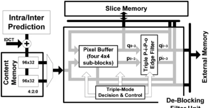
This section presents a high-throughput architecture with the hybrid filtering schedule. The associated block diagram is de-picted in Fig. 3. Two dedicated single-port SRAMs (content and slice) are designed to not only store the current and neighboring pixels but also achieve an efficient data access. Furthermore, we propose the hybrid filtering schedule and introduce four 4 4 pixel buffers to reduce the numbers of processing cycles.
A. Memory Organization
The proposed memory organizations are twofold; content and slice memory. The address depth is decided by the YUV for-mats (4:4:4, 4:2:2, or 4:2:0), and the data word size is based on the 32-bit of the column-of-pixel (CoP) [see Fig. 4(a)] for the reduced memory accesses in the intra/inter prediction unit [8]. The content memory stores the unfiltered pixels prior to the de-blocking filter. Moreover, it adopts the ping-pong structure and stores two MBs to resolve the structural hazard when reading and writing processes occur simultaneously. Hence, the content
memory is of size (in 4:2:0). On the
other hand, the slice memory stores the upper and left neigh-boring pixels for follow-up filtering processes. Considering a
TABLE II
COMPOUNDMETHOD FOR THESTRENGTHDECISION
Fig. 2. (a) Data flow and (b) pseudo-code of the in/post-loop algorithm.
Fig. 3. Block diagram of in/post-loop dedblocking filter.
frame size of in Fig. 4(b), each square represents the 16 16 MB. Each MB contains 16 points and 4 4 pixels
within each point. When filtering processes are performed from the MB index to , upper and left neighbors will up-date the pixel values as the arrows indicate. The shaded region should be kept when the filtering index is . Therefore, the size of slice memory is for the 4:2:0 format.
B. Hybrid Filtering Schedule
We propose a hybrid filtering schedule to reuse the interme-diate data and thereby eliminate the additional memory accesses when deblocking filter changes the filtered edges from vertical to horizontal direction. Fig. 5(a) describes the standard-defined filtering orders where vertical edges are filtered first, followed by horizontal edges. However, a main drawback of this direct approach is that the intermediate data have to be written into the internal memory in one direction and then read again in another direction. For instance, considering the black region in Fig. 5(a),
Fig. 4. Data organizations of (a) content and (b) slice memory.
Fig. 5. (a) Standard-defined and (b) proposed schedule.
Fig. 6. (a) Partitioned MB and (b) each time index for the hybrid filtering schedule.
the edge #1 will be filtered first, followed by the edge #5. After that, the processing data in the black region cannot be reused since the filtering orders between vertical and horizontal edges become longer (i.e., #5 versus #17). Therefore, the memory accesses are required in both vertical and horizontal directions. To alleviate this problem, we develop a hybrid filtering schedule without affecting the standard-defined data dependency in Fig. 5(b) and all unshaded numbers are performed in 8 8 post-loop filters. Considering the orders in the black region to perceive a contrast, the black region can be reused because the orders between different directions become close. Therefore, the
proposal prevents the data re-access for different directions and reuses the intermediate pixels to reduce the processing cycles.
Though Sheng et al. [6] proposed a novel schedule to reduce the processing cycles, this schedule requires eight 4 4 sub-blocks as the kept buffers. To reduce this buffer size, each MB can be partitioned into two main parts (i.e., Deblocking
Filter-MB-Upper or Lower) in Fig. 6(a), and each part is composed of eight
time indexes to perform the filtering procedure in Fig. 6(b). Each bold line represents the edge to be filtered in the corresponding time index. As a result, our kept buffer size is four 4 4 sub-blocks where is located on shaded regions. By the same way, the proposed schedule is performed on the chroma MB as well.
C. High-Throughput Architecture
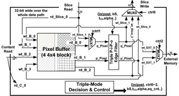
The high-throughput architecture with hybrid filtering schedule is presented in this subsection. The detailed signal flow of Fig. 3 has been redrawn in Fig. 7. Specifically, all signals are 32-bit wide and possess the CoP organization. The signal names represent the writing/reading to/from the storage modules in-cluding the slice, content, and external memory. Accordingly, the behavior of Fig. 7 can be divided into two main parts: writing
processes and
reading processes .
The key idea of the high-throughput architecture is that the content memory is exploited only for the reading processes. In Fig. 7, the writing signal, is activated on the edges
Fig. 7. Detailed architecture for the in/post-loop deblocking filter.
TABLE III
VALUES OFt WITH AFUNCTION OFQP
TABLE IV
POST-LOOPFILTERINGPERFORMANCE INTERMS OFLUMAPSNR
6, 10, 14, and 16 because the lower subblocks become the upper neighboring subblocks of [see Fig. 6(a)]. Therefore, the writes the filtering results into slice memory for follow-up filtering processes. For the , it writes filtered data into the external memory. On the other hand, the reading signal, , is activated on vertical edges while the is valid on horizontal edges. In addition, the directly feeds through the pixel buffers. In other words, content memory is employed for the reading processes, and there is no need to write the filtered results into the content memory in one direction and thereby read them in another direction. Therefore, the proposal exploits four 4 4 buffers to reuse the intermediate pixel and eliminate the writing accesses of content memory.
IV. SIMULATION ANDIMPLEMENTATIONRESULTS
A. Performance Evaluation
The modifications of the post-loop filter improve the integra-tion efficiency at a cost of slight performance degradaintegra-tion. For the experiments of MPEG-4’s post-loop filter, the thresholds of and (see Table II) are employed without loss of generality. Further, we adopt Table III as the induced term of . QP stands for “quantizer precision,” and we use 5-bit as a default value that ranges from 0 to 31. All alterations of the MPEG-4’s post-loop algorithm have been addressed in Sec-tion II, and specific results are given in Table IV. All sequences are defined in CIF (352 288) and intra-period 15 with 30 fps
Fig. 8. Subjective quality comparison between the post-loop filter and proposed design. (a) Without filter. (b) MPEG-4’s filter. (c) Proposed. TABLE V
CYCLEANALYSIS OF THEDEBLOCKINGFILTERS
throughout 300 frames. We show that the performance degrada-tion is less than 0.05 dB as compared to the MPEG-4’s post-loop filter [2]. From the subjective point of view, we capture the 20th frame to give a comparison in Fig. 8.
B. Processing Cycle Analysis
To clarify the cycle reduction, we formulate processing cycles in (1) and (2) where C.C. means cycle counts. The overall cycles of deblocking filters can be considered as a combination of the pre-process, filter-process and post-process. The pre-process is an initial stage which loads external data (neighboring pixel) into slice memory while the post-process is a write-back stage which writes filtered results from slice memory to external memory. In the filter-process, the pro-cessing cycles include slice or content Memory to pixel Buffers (i.e., -to- ), generic filtering, and pixel Buffers to slice Memory (i.e., -to- ). The processing cycles of the generic filtering are which become a lower bound to fulfill filtering processes if the rest of processing cycles are zero in an ideal case.
Total Cycle Counts
(1)
(2) Based on the proposed hybrid filtering schedule, the overall cycles are 243 and close to a lower bound of processing cy-cles. Table V shows a detailed cycle analysis. In our design, the neighboring pixel can be fetched from the slice memory, and the filtered results are written into the external memory without going through the slice memory. As a result, the cycle counts of the pre-process and post-process can be eliminated. In the filter-process stage, the evaluated cycle counts are 148 cy-cles for luma MB and 88 cycy-cles for chroma MB. Specifically, we take 8 cycles (DF-MB-U+ DF-MB-L) in the
-to- stage. There are 4 32 cycles required to filter hori-zontal and vertical edges in a luma MB. Moreover, we need 12 cycles (i.e., -to- ) to write the filtered results for the
edges . Overall, we need 148 (i.e., )
cycles to accomplish filtering processes in a luma MB. By the same analysis, we need 88 (i.e., for each chroma) cycles in a chroma MB. Therefore, there are total 243 cycles with extra 7 cycles for the data hazard (ie., ). The cycle overheads in the control logic can be neglected since it acts as a pipelined fashion. In addition, the processing cycles of the post-loop filter are identical to that of the in-loop filter because they share the same architecture and control flows. In
TABLE VI
HARDWARESUMMARY FOR THEDEBLOCKINGFILTER
conclusion, 243 cycles are close to a lower bound (192 cycles) by the proposed schedule.
To enhance the system performance, this VLSI solution is designed to achieve high throughput as well as integration effi-ciency. The proposal is implemented using a 0.18- m CMOS process. Excluding the internal memory, the synthesized gate counts are 21.1 K which is reduced to 70% of the original design that realize in-loop or post-loop filtering process sep-arately. Moreover, it achieves 4 10 MB/s of throughput rates when operating at 100 MHz. Finally, Table VI reveals that the throughput rates of the proposed design are about 1.5–2.5 times larger than that of existing approaches [4]–[6].
V. CONCLUSION
In this paper, the algorithms of an in/post-loop deblocking filter and its architecture have been presented. Firstly, we de-velop an in/post-loop deblocking algorithm that can be recon-figured as a filter for the H.264/AVC or MPEG-4 standard re-quirements. In particular, we propose a triple-mode decision and triple P-i-P-o edge filter to improve the integration efficiency. The overall cost can be reduced by 30% compared to the sepa-rate design. Secondly, we propose the hybrid filtering schedule to reuse the intermediate data and reduce processing cycles. We use four pixel buffers to perform the horizontal and vertical edge filter in a hybrid scheduling flow. Finally, an in/post-loop
deblocking filter with hybrid filtering schedule is implemented using a 0.18- m CMOS process. 4 10 MB/s of throughput rates can be achieved at a 100-MHz clock rate and is 1.5–2.5 times higher than that of existing designs [4]–[6]. Therefore, the proposal is suitable for high-throughput or multiple standard re-quirements such as Digital-TV and HD-DVD devices.
REFERENCES
[1] S. Srinivasan, “Windows Media Video 9: Overview and applications,” Signal Process.: Image Commun., vol. 19, pp. 851–875, 2004. [2] S. D. Kim, J. Yi, H. M. Kim, and J. B. Ra, “A deblocking filter with
two separate modes in block-based video coding,” IEEE Trans. Circuits Syst. Video Technol., vol. 9, no. 1, pp. 156–160, Feb. 1999.
[3] P. List, A. Joch, J. Lainema, G. Bjontegaard, and M. Karczewicz, “Adaptive deblocking filter,” IEEE Trans. Circuits Syst. Video Technol., vol. 13, no. 7, pp. 614–619, Jul. 2003.
[4] Y.-W. Huang, “Architecture design for deblocking filter in H.264/JVT/ AVC,” in Proc. ICME, Jul. 2003, vol. 1, p. 1-693-6.
[5] S.-C. Chang, W.-H. Peng, S.-H. Wang, and T. Chiang, “A platform based bus-interleaved architecture for de-blocking filter in H.264/ MPEG-4 AVC,” IEEE Trans. Consum. Electron., vol. 51, no. 1, pp. 249–255, Feb. 2005.
[6] B. Sheng, W. Gao, and D. Wu, “An implemented architecture of de-blocking filter for H.264/AVC,” in Proc. IEEE ICIP, Oct. 2004, vol. 1, pp. 665–668.
[7] S. Srinivasan, T. W. Holcomb, and P. Hsu, “In-loop deblocking filter,” U.S. Pat. 2005/0013494 A1, Jan. 20, 2005.
[8] T.-M. Liu, W.-P. Lee, T.-A. Lin, and C.-Y. Lee, “A memory-efficient deblocking filter for H.264/AVC video coding,” in Proc. IEEE ISCAS, May 2005, pp. 2140–2143.