Proceedings of the 1996 IEEE
lntemational Conference on Robotics and Automation Minneapolis, Minnesota
-
April 1996Adaptive Fuzzy Hybrid Force/Position Control for Robot
Manipulators Following Contours of an Uncertain Object
Feng-Yih
Hsu'
and Li-Chen
F ' U ~ , ~
Dept.
of
Electrical Engineering'
Dept.
of
Computer Science & Information Engineering2
National Taiwan University, Taipei, Taiwan, R.O.C.
Abstract
This paper proposes an adaptive fuzzy hybrid force/position control scheme, which can force the end eflector of robot manipukators to follow the contour of an object in lack of knowledge of the exact ge- omeotric shape. The control objective is to perform hybrid force/position control regardless of the exis- tence of
the
manapdator dynamics. The control algo- rithm proposed can adaptively update the position tra- jectory command as well as fuzzy contml d e s , and consequently, guarantee the global stability and drive the tracking errors to a neighborhood of zero. The present work is applied to the control of a five degree- of-freedom(DOF)
articulated robot manipulator. Sim- ulation results show that the proposed contml architec- ture is featured in fast algorithmic convergence.1
Introduction
A human, even if blind, can adapt to the uncertain surrounding environment by touching various objects there and gradually updating his perception about that world. But today's robot manipulators are lack-
ing such kills, particularly, with respect to the var- ied contour-following tasks involving mechanic opera- tions. The robot manipulators have to be taught or told in advance what the exact contour of object is so that they know how to perform the contour-following
task. As a result, it will reduce flexible application of the robot manipulators when versatile tasks are desig- nated to them. In fact, force sensing along the surface of an object can help the robot manipulators to rec- ognize the uncertain environment, similar to human sensing. There have been several researches efforts re- lated in estimation of constraint surface by force sens- ing [1]-[2].
Another occasion where the force sensing is applied
to the robot manipulators is force/position control in performing contour-following tasks, for example, de- burring tasks and grinding tasks. To achieve that con- trol task, the robot end-effector has to follow the de- sired position trajectory as well as the desired force trajectory. Being different from the problem of sole position control, the above problem is not only to con- sider the robot manipulator dynamics but also to con- sider the interaction between the robot manipulators and the environment. Therefore, a force model to express the relation between the robot manipulators and the environment is necessary to analyze the prob- lem. So far, the control schemes incorporating differ- ent kinds of force model may be classified into three types mainly: constraint robot control [3], compliant control [4]-[5] and hybrid force/position control[6]-[8]. For robot manipulators to perform contour-following tasks, the hybrid force/position control turns out to be a more suitable control approach since most object sur- faces to be contacted are rigid enough, compared the passive devices mounted onto the end-effector
,
such as some elastic strings, so that transient excessive con-tact force can be avoided. In this paper, we focus our
attention on the hybrid force/position control with un- certain shaped object.
On the other hand, the adaptive fuzzy control schemes have been demonstrated with better perfor- mance in the presence of system uncertainty [9]-[lo]. Here, we will modify it to solve the problems men- tioned above.
2
Problem Formulation
Consider a robot manipulator whose end-effector is in contact with an object with an aim to compliantly
robot
r
n
end effcctor
object
U
Figure 1: The robot performing contour-following
following a desired contour on the surface of the object,
as depicted in Fig. 1. For simplicity in the coordinate transformation, we assume that the Cartesians coor- dinates of the end-effector in the world frame { W } , x c may be represented as a function of its joint coordi- nates in the reference frame, q , i.e.,
where xc = [ x c l , - . . ,xC6lT =
[ZF,~;]~
with x p ER3
being the position vector and xm EE3
being the ori- entation vector, and q = [q1,
-
.
.
,
qnIT. Differentiating equation (1),
we can derivewhere J ( q ) E is a Jocabin transform matrix and is assumed to be of full rank for q lying in a compact set in the joint space, so that there exists a one-to- one mapping between xc and q in a properly defined compact set [ l l ] . Thus, J has a sudo-inverse matrix J + , satisfying
JJ+
= I . Then, we can derive the dynamics of the robot manipulator in the world frame as follows:M ( x c ) Z C
+
C ( x c , k c ) k c+
G ( x c )+
D ( x C , k c ) = F, + F, where M ( z c ) E E6x6 is the inertia matrix, C ( x c , i c ) k cis the vector representing the centrifugal and Coriolis forces satisfying M
-
2C is a skew-symmetric matrix,G(z,) is the vector of gravitational forces, D ( x c , k c ) is the vector of friction forces, Fc is the vector con- sisting of contact forces and moments, and F is the vector consisting of control input forces and moments.
Also, the torque vector T in the joint coordinate can
be derived as T = J T ( q ) F .
Given the robot dynamics (3), more importantly, the control task is to perform the force control as well
(3)
as the position control. Therefore, in addition to the dynamics terms of robot manipulators, the contact force term Fc in (3) has to be compensated, partic- ularly, in the force control problem, leading to a force model required to be analyzed. From Fig.1, when the end-effector compliantly performs the contour- following on the object, the desired force trajectories are usually designed such that the force elements are along the directions normal to the object’s surface, whereas the desired position trajectories are along the directions tangent to the object surface. To make such complex problem more tractable, some mild assump- tions are given below.
There is only single contact point. The shape of the object is smooth.
Hook’s Law can be applied to the contact force model.
The friction forces are small and hence can be negligible.
x,, i,, fc and
jc
are measurabe.Based on the assumptions above, the moment (vec- tor) is approximately zero for the single contact point and the force elements tangential to the object sur- face are regarded as zero. Therefore, the vector of contact force and contact moment is defined as Fc =
[fTm3T = [fcT,O,O,OIT, where fc and m, represent
the force vector and the moment vector, respectively. fithermore, applying Hook’s Law to the contact force model, fc can be found as
f,
= -k,(x, -zs), where zsis the end-effector position on the surface of the object before deformation and satisfies that xp
-
z8 is parallel As mentioned earlier, our objective is to perform hybrid force/position control in the contour-following task. However, as a matter of fact, the precise “ de-sired contour ” on the object surface is difficult to be
specified in the presence of uncertainty in the object shape. Hence, the desired positional trajectory after priorly described in the worlc! frame as
Gd
E R3 along the undeformed contour on the object surface, needs to be repetitively corrected in a moving frame until the aforementioned objective is met. Therefore, consider a moving frame as { V} affixed to xs consisting of three orthonormal bases n1, n2, and n3 as depicted in Fig.2. The first basis vector n1 representing the direction ofcontact force fc is expressed as
to fc.
f c
llfcll
’
virtual desired contour
/ A ”
{
13
moving frame{
w>
world frameFigure 2: The end effector contacting the object under assumption that the end-effector i s always in contact with the object. Obviously, in the absence of friction force, n1 will be normal to the object surface assuming the deformation is rather small. After nl is given, the desired force trajectory f d can then be
easily expressed in this moving frame as follows:
f d = f d m n l , (5)
where f d m = llfdll is the scalar desired force mag- nitude. The second basis vector nz representing the direction of the desired positional trajectory direction is constructed via the following procedure. First, let
(6)
A h h f C
e, = x p d
-
2 8 = XpGpd-
( x p+
k,)
represent the virtual position error between the virtual desired trajectory
Sd
and the contact point on the undeformed object surface 5 , . Next, we define thetrajectory error e, tangential to the object surface as e, = e,
-
(E,.
n 1 ) n l = 2,-
E T n l n l ,where
‘+’
represents the inner product operator. Then,122 is defined as follows:
(7) A
n~ =
{
g - p IlesII#
0;0, otherwise;
Finally, the last basis vector is given as n3 = n l x nz, where ‘ x
’ represents the outer product operator.
[Remark] :
In fact, if the direction of friction force is opposite to the direction of the end-effector velocity, then n1 can
be modified as follows:
where nu =
&.
Practically speaking, the end-effector position ex- pressed in the frame { V } will have nonzero value only along n1 axis but zero value along the other axes. Let
zul denote that nonzero scalar value, and thus the practical end-effector position may be written as
x p = x ,
+
xV1n1Clearly, x , will exactly follow if e^, can approach zero. Fwthermore, let the desired position trajectory be repetitively updated as follows:
(9)
where the index k is the number of times for which the end-effector goes around the object.
To derive the contact force model subject to uncer-
tain geometric object surface containing the point, x g .
So long as ke is precisely known and the desired force trajectory f d is formulated as follows:
(11)
f d m
ke
f d = $ - n i = k x f d n l ,
where x f d = f d m is given, then the force error vector ef = f d
+
fc = e f m n l-
-
ktZ(xfd - x ) n1can be replaced by the the position error vector epf =
e z f n l , where ezf = x f d
-
x u l . Define the desiredposition trajectory in the world frame can be expressed
as follows:
zPd = x ,
+
e,+
z f d n l1
k e
= x p
+
-
j c + e ,+
x f d n l (12)Hence, the dynamics (3) can be transformed to a posi- tion control problem. In fact, if x p can approach x p d , then the contour-following task is solved. When the desired position trajectory xPd is given by equation
(12), the desired orientation trajectory is denoted as
Xmd, which is designed from the need of task or from
the moment siganls [6]. Let X d = [ X p z X m : l T represent
the desired position/orientation trajectory. Then, the tracking error e is defined as e = zc
-
x d = [e;,where e,, = xpd
-
x p and em = xmd - x m . Now define the sliding mode vector s = [ S I ,.
-
.
) sgIT as s = e+
Xe,where X is a positive constant so that the dynamic equation (3) can be rewritten as follows:
M i zz M 3 ,
+
CX,+
D
+
G-
F,-
F (13)Design the control law as
where K = diug(kl
. .
,,
k6) is a positive definite ma- trix, h = [h1,.--,h6lT = MX,+
CX,+
G+
D is the robot dynamics term with 5, = x d+
Xe, and vector, then equation (13) can be written as:fe = [*kp k Tn l n r , O,O,
oIT
is additional compensationM i = - K e S
-
C S , (15) where K , is expressed as:In fact, K , is a positive definite matrix and can be Apparently, if the robot dynamic system is reduced into the equation (15) by the control law (14), then the
system tracking error e will be driven to zero asymp- totically [12]-[13]. Unfortunately, the prsent prob-
lem is much more difficult than those proposed works
[8],[10] because z s , e, and n1 now involve the system states such as x p and
f,,
and the derivatives of those states are hardly measurable, which hence results in inaccessibility to the signal Z p d .On the other hand, it is well known that computed torque control algorithm appears to be very compli- cated in the case of multi-degree-freedom robot manip- ulators. The sensing time of the force/torque sensor is much longer than that of the motor encoder, measur- ing the position of robot manipulators. Consequently, to obtain reasonally good performance of the overall controlled system, it is important to maintain high enough control servo rate as well as to take as much much manipulator dynamics into account as possible, the control algorithm to be designed should meet the objectives of complete dynamics control and simple implementation. Given this aim, in the next section we will propose an adaptive fuzzy hybrid force/position control scheme as a solution.
derived from the expression of nlnTep = e p f = K e f . 1
3
Adaptive
Fuzzy
Hybrid
Force/Position Control
Referring to section 2, the control law is given as
follows:
where fa = [ f a l ,
. .
,
fs6IT represents the fuzzy controlcompensator to compensate for the nonlinear function vector h consisting of the robot dynamics and the addi- tional uncertainties excited by the contact force. Con- sider the fuzzy rule structure based on as a decentral- ized concept, consisting of with R I , RP,
.. ., and
R6F = K s
+
fd+
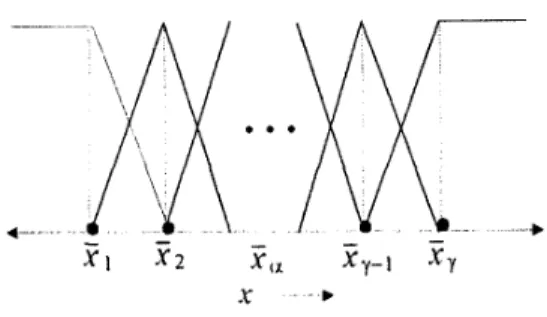
fe + f a , (16)Figure 3: The membership function candidates
rule tables as follows:
Rl[i] : If x c l is L r ) and s1 is M ! i ) , then f S l is QY’
&[i] : 1fz,6 is
I,!)
and 36 is M : ~ ) , then f a 6 isQP)
(17)
where L f ) , M j i ) and
0:’
represent the fuzzy sets associated with the i-th rule of the j-th rule table, corresponding to fuzzy variables x c j , s j and f S j , re-spectively. Based on this rule structure, the sup-min compositional operator and center-of-area defuzzifier strategy are choosen here [lo]. Thus the j-th element of the fuzzy output vector fa can be derived as follows
[lo]:
f 83 . = @T<. 3 3 ’ (18)
where Oj is the j-th column vector of an ‘Y x 6 constant
parameter matrix 0 and is the j-th column vector of an ‘Y x 6 regressor matrix
E ,
withT
being the rule number for every rule table.Here, our objective is to determine an optimal parameter matrix, with minimal magnitude, O* =
[Of
-
.
SO;. . .
Og] that can robustify the closed-loop system, and a suitable regressor matrix which can re- duce the complex implementation to a simple one. To achieve this goal, the membership functions p ( z c j ) and p ( s j ) (see Fig. 3) are set to be:as 5 =?Fa; (0,1], otherwise.
p ( z ) =
{
i!i:
as 5 2za+l
or 55
Fa-l; (19)where ?Ea is denoted ils the center of a fuzzy set with
Q being any integer index and satisfying 1
<
Q<
y,leading to much shorter computation time and facili- tating subsequent determination of the parameter ma- trix [lo]. Before defining the optimal parameters, we
Figure 4: The A-type robot arm
define the modified sliding mode vector SA,
as
follows:{:-CXj, a S S j <aj;
s A j = ~j
-Pj,
a~ sj>
Bj;
(20) othewise.It is obvious that if SA,
#
0, then sj will be outsidea deadzone range
4
= [aj,Pj].
Based on this fact, then the j-th column vector of optimal parameter matrixQ* is d e f k e d follows:
Qj
= crrgnin[szcp,,EQjTesgn(sai)2
[hjl], for S A jf o ,
(21)
where z = [ Z : , S ~ ] ~ is all input fuzzy variables andE is a compact domain set. Consider the adaptive control law is given as follows:
Qj = r s ~ ~ ( j , for z E E , (22)
where T is a positive constant. Furthermore, as- sume that
lhjl
can be bounded by a smooth function H j (scj, sj) when z falls into the compact domain set E . Then, the following theorem is valid.Theorem 1 If the control law and the update law are given as in equation (16) and in equation (22), then the tracking error vector e will converge to a neighborhood of zero asymptotically.
4
Simulation Results
A
five degree-of-freedom (DOF) articulated robot arm is set up in the Intelligent Robot Laboratory of Dept. of Computer Science & Information En- gineering in National Taiwan University, as depictedin Fig. 4. An elliptical cylinder object is located on the table, expressed as
$
+
= 1 and 0 <_ x c 35
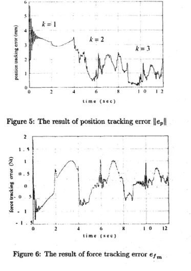
50. At the beginning, the virtual desired contour is given as a circle of radius 50" in zcl -xc2t i m e ( s e c )
Figure 5: The result of position tracking error llepl\ _______----
t . 5 ,
l i m e ( s e c )
Figure 6: The result of force tracking error efm
plane with the expression:
$ +
~w.
= 1 andsc3 is a sinusoidal wave. The desired position trajecto- ries corresponding to this virtual contour are given as s c l ( t ) = 50cos(0.5xt), z c z ( t ) = 3 0 0 + 5 0 s i n ( 0 . 5 ~ t ) and zc3(t) = 25(1 - ms(0.57~t)). The desired force magni- tude trajectory fdm is given as fdm = 10-5ezp( - t ) N t
with inintial contact force 5 N t being given. The total rule number of fuzzy controller is 6 x 21 x 21 and initial parameter matrix of fuzzy rules, 0, are set to zeros. The stifhess
ke
= 1 0 ( N t / m m ) is given. The norm of position trajectory error, llepll is listed in Fig. 5 .At
the beginning, since initial parameter matrix are set to zeros, which is similar to only use the PD controller to compensate for the uncertainties in the first period of tracking motion, after the first period the tracking er- ror is quickly driven toward zero. On the other hand, the force error e f m is given in the Fig. 6, we can find that the error is converging to zero. Besides, the vir- tual desired position trajectoryGd
converges to the real contour of the object, shown in Fig.7.60, initial virtual dcsircd contour (h ‘1) dcsircd contour
(k
=2) 100 5 0 250 -50Figure 7: The result of virtual desired trajectory ii&
5
Conclusions
We had proposed an adaptive fuzzy hybrid force/position controller, which can update fuzzy rules to compensate for the robot dynamics along with the force dynamics induced by the contact between end- effector and object, and identify the actual desired contour of the object. For illustration, a simulation is conducted and satisfactory results have been observed. Actual experiment is under way.
References
M. Blauer and P. R. Belanger, “State And Pa- rameter Estimation for Robotic Manipulators Us- ing Force Measurements, ” IEEE h n s . Autom.
Cont., vo. 32, Dec. 1987
T. Yoshikawa and A. Sudou, “ Dynamic Hybrid
Poition/Force Control of Robot Manipulators--0n- Line Estimation of Unknown Constraint, ” IEEE
Bansactions on Robotics and Automation vo. 9, no. 2, p p . 220-225, April 1993
J.
-H. Jean and L.-C. Fu, “ An Adaptive ControlScheme for Coordinated Multimanipulator Sys- tems, ” IEEE h n s a c t i o n s on Robotics and Au-
tomation vo. 9, no. 2, p p . 226-231, April. 1993 S. A. Schneider and Robert H. Cannon, Jr, “ Ob-
ject Impedance Control for Cooperative Manipu- lation: Theory and Experimental Results, ” IEEE
Tkansactioas on Robotics and Automation VO. 8,
no. 3, pp. 383-394, June 1992
[5] W. McCormick and H. M. Schwartz, “ An Inves-
tigation of Impedance Control for Robot Manip- ulators,” The International Journal of Robotics Research vol. 12, no. 5, October 1993, pp. 473-489
[6] K. Guglielmo and N. Sadegh, “ Implementating a
Hybrid Learning Force Control Scheme, ” IEEE
ControE Systems vo. 14, no. 1, p p . 72-79 Feb. 1994 [7] D. Jeon and M. Tomhuka, “Learning Hybrid Force and Position Control of Robot Manipulators,” IEEE iYansactions on Robotics and Automation
V O . 9, 110.
4,
p p . 423-432, Aug. 1993[8] M. H. Raibert and J. J. Craig, “Hybrid Posi-
tion/Force Control of Manipulators” ASME Jornal
of Dynamic Systems, Measurement, and Control vol. 1 0 2 ~ ~ . 126-133, 1981
[9] F. -Y. Hsu and L. -C.
Fu,
“Adaptive Robust Fuzzy Control for b b o t Manipulators’’
IEEE Confer- ence on Robotics and Automation, p p . 629-634, 1994[lo] F. -Y. Hsu and L. -C.
Fu,
“A New Design of Adap- tive Robust Fuzzy Controller for Robot Manipula- tors, ” IEEE Conference on Robotics and Automa-tion, p p . 863-868, 1995
[ll] J. Marsden, Elementary Classical Analysis. San
[12] J-J E. Slotine and W.
Li,
Applied Nonlinear Con- trol, Englewood Cliffs, NJ: Prentice Hall, pp. 278- 284,1991.[13] G . Niemeyer, J-J E. Slotine, “ Performance in
Adaptive Manipulator Control ”
,
The Interna-tional Journal of Robotics Research, vol. 10, no. fianciso: W. H. Reeman, 1974