Brief Papers
_______________________________________________________________________________Variable Structure-Based Nonlinear Missile Guidance/Autopilot Design With
Highly Maneuverable Actuators
Fu-Kuang Yeh, Kai-Yuan Cheng, and Li-Chen Fu
Abstract—In this brief, we propose a variable structure based nonlinear missile guidance/autopilot system with highly maneuver-able actuators, mainly consisting of thrust vector control and di-vert control system, for the task of intercepting of a theater ballistic missile. The aim of the present work is to achieve bounded target interception under the mentioned 5 degree-of-freedom (DOF) con-trol such that the distance between the missile and the target will enter the range of triggering the missile’s explosion. First, a 3-DOF sliding-mode guidance law of the missile considering external dis-turbances and zero-effort-miss (ZEM) is designed to minimize the distance between the center of the missile and that of the target. Next, a quaternion-based sliding-mode attitude controller is devel-oped to track the attitude command while coping with variation of missile’s inertia and uncertain aerodynamic force/wind gusts. The stability of the overall system and ZEM-phase convergence are an-alyzed thoroughly via Lyapunov stability theory. Extensive simu-lation results are obtained to validate the effectiveness of the pro-posed integrated guidance/autopilot system by use of the 5-DOF inputs.
Index Terms—Attitude control, bounded target interception, nonlinear system, quaternion, variable structure.
NOMENCLATURE Acceleration vector. Disturbances vector. Pitch angle of nozzle. Yaw angle of nozzle. Thrust vector.
Gravitational acceleration vector. Moment of inertia matrix. Nominal part of . Variation of .
Distance between nozzle and c.g. Displacement vector. Mass of the missile.
Derivative of . Magnitude of thrust. Quaternion.
Position vector.
Manuscript received October 1, 2002; revised December 4, 2003. Manuscript received in final form February 9, 2004. Recommended by Associate Editor P. K. Menon. This work was supported by the National Science, Taiwan, R.O.C., under Grant NSC 92-2212-E-002-044.
F.-K. Yeh is with the Chung-Shan Institute of Science and Technology, Taoyuan, 325, Taiwan, R.O.C. (e-mail: [email protected]).
K.-Y. Cheng and L.-C. Fu are with the Department of Electrical Engineering and Information Engineering, National Taiwan University, Taipei, 106, Taiwan, R.O.C. (e-mail: [email protected]).
Digital Object Identifier 10.1109/TCST.2004.833622
Unit vector of . Magnitude of . Present time. Torque. Velocity vector. Exhaust velocity. Angular velocity vector.
A. Subscripts
Body coordinate frame. Disturbances. Desired. Error. Gravity. Missile. Initial time.
Perpendicular to line-of-sight (LOS). Divert control.
Target/Thrust.
I. INTRODUCTION
G
ENERALLY speaking, there are two principal phases for missiles that try to intercept theater ballistic missiles. One is the midcourse guidance [1], the stage before the missile can lock onto the target by its own sensor, whose task is to deliver the missile to some place near the target subject to some addi-tional conditions, such as suitable velocity or appropriate atti-tude. On the other hand, the homing guidance [2], i.e., the ter-minal guidance, will refer to the period after the distance be-tween the center of the missile and that of the target is less than some prespecified value, which often leads to a situation where the sensor on the missile can lock onto the target. Based on the concept of the proportional navigation (PN) guidance law, con-stant bearing guidance is often employed on the intercept mis-siles. Ha and Chong developed a new command to line-of-sight (CLOS) guidance law for the short-range surface-to-air missile via feedback linearization [3], and then its modified version [4] with improved performance. As for Moon et al. [9], they pro-posed the missile guidance law using variable structure con-trol, where the input command is derived under the condition wherein the target acceleration is treated as an uncertainty. An adaptive sliding-mode guidance of a homing missile was pre-sented by Zhou et al. [10] to online estimate some necessary parameters so as to provide robustness to the disturbances. 1063-6536/04$20.00 © 2004 IEEEBesides guidance, attitude control is another important issue to be addressed for successful missile’s operation. Quaternions are used in navigation and guidance algorithm to eliminate the singularities present with direction cosine matrices. It is quite often that quaternion representation has been adopted to de-scribe the attitude of a spacecraft [5], because it is recognized as a kind of global attitude representation. To cope with the non-ideal factors surrounding the spacecraft under attitude control and to enhance the robustness property of the system, sliding mode control has been employed by Chen and Lo [6], which was then followed by a smooth version [7] incorporating a boundary layer as has been proposed by [8] to avoid the chattering phe-nomenon, but at the price of slightly degrading the tracking ac-curacy. A missile equipped with thrust vector control (TVC) can effectively control its acceleration direction [1] when the missile’s fin fails, which in turn implies that the maneuver-ability/controllability of the missile can be greatly enhanced during the stage when the speed of the missile is slow and/or the air density surrounding the missile is low. In this brief, we in-vestigate the variable structure (VS)-based missile guidance/au-topilot problem for a missile equipped with TVC and divert con-trol system (DCS) so that the intercepting missile is able to ful-fill the purpose of successful interception of an inbound target missile in a single intercepting phase.
II. PRELIMINARIES
A. Equations of Motion for Missiles with TVC
The motion of a missile can be described in two parts as fol-lows:
Translation:
(1)
Rotation:
(2) where , and all the variables are defined in the nomenclature.
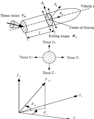
After referring to Fig. 1(a)–(c), the force and torque exerted on the missile can be, respectively, expressed in the body coor-dinate frame as
(3) (4)
where is the aforementioned variable
moment in the axial direction of the missile. Let the rotation matrix denote the transformation from the body coordinate frame to the inertial coordinate frame. From (1) to (4), the mo-tion model of the missile can then be written as
(5)
(6)
where and .
B. Zero-Effort-Miss Phase
Assume that both the missile and the target are moving only with constant gravitational acceleration, i.e.,
(7) Therefore, the relative position vector and the relative velocity vector at can be, respectively, expressed as
(8) Thus, zero-effort-miss (ZEM) can be computed as
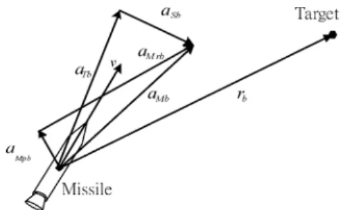
(9) If the convergence of is fast enough, the relative velocity will soon almost be lined up with LOS (see Fig. 2) and, hence,
. Apparently, from (9) one can then conclude that ZEM as , which is our ideal goal.
III. GUIDANCESYSTEMDESIGN
The equations of relative motion in terms of the relative
po-sition and the relative velocity are
as follows:
and (10)
where , , and the translation motion of a
missile is defined as (1).
To proceed, we first derive the equation of the relative motion
perpendicular to the LOS ( ) as follows:
(11)
where and
.
Referring to (11), an adequate design of is the following: (12)
where is a positive definite
diag-onal matrix, and is a switching function of the sliding mode control, which readily yields
(13) Let be a Lyapunov function candidate, and evaluate the time derivative of along the trajectories of the system (13) as follows:
(14)
Fig. 1. (a) TVC actuator with single nozzle and rolling torque scheme. (b) Missile’s divert control system (bottom view). (c) Two angles of TVC in body coordinate frame.
Fig. 2. Relative velocity between missile and target.
where we use the fact . It is evident that if we choose
, , 2, 3 and
, then (14) becomes
(16) where ( ) is the minimum eigenvalue of . Thus, via Lyapunov stability theory, we can conclude that the speed component will gradually diminish before ZEM phase is reached.
IV. AUTOPILOTSYSTEMDESIGN
The attitude of a rigid body may be described in quaternion. Thus, it can be defined as four parameters involving and , i.e.,
(17)
In theory, it can be verified that the time derivative of a quater-nion is as
(18) To demonstrate the robustness of the controller, we allow (2) and (18) to be subjected to (bounded) input disturbances and
the uncertain quantities and , where ,
. Let the torque input be proposed as
(19)
where , .
, ,2,3, whereas is a sign function, and is a sliding surface variable defined
as , with . If the
inequality condition shown below can be guaranteed
(20) where
(21) whose bounding function is obviously a function of , , , and . Here, let the Lyapunov function candidate be set as
.
From the sliding-mode theory, once the reaching condi-tion is satisfied, the system is eventually forced to stay on
the sliding manifold, i.e., , where
. It has been shown that [2] the system origin is indeed exponentially stable. Taking the first-order derivative of , we have
(22) Therefore, it is evident that (22) becomes
(23)
for , where is the minimum eigenvalue of ,
a positive definite diagonal matrix. As a result, the exponential stability and robustness of the autopilot system can be achieved.
V. INTEGRATEDSTABILITYANALYSIS
To verify the stability of the overall system, we define the Lyapunov function candidate of the overall system as
. The first-order time derivative of the Lyapunov function can be derived as
(24) referring to (14) and (22).
Now, we are ready to state the following theorem which will provide conditions under which the proposed overall sliding mode guidance and autopilot system controlled by TVC, DCS, and rolling moment guarantee the stability of the entire system and the target-reaching objective is achieved.
Theorem 1: Let the equation of relative translational motion
perpendicular to LOS and the relative rotational motion be de-scribed as in (2), (11), and (18), the sliding mode guidance law be proposed as in (12), the torque input of the autopilot be given as in (19), and the guidance law be switched to ZEM phase when
. If is such that , where is the
starting time, and is bounded away from zero, then the in-tegrated overall guidance and autopilot systems will drive the missile to enter the ZEM phase eventually so that the bounded target interception of the integrated system can be achieved.
Sketch Proof of Theorem 1: From (24), the expression of
can be simplified as
(25)
Let the desired acceleration be defined in (12) perpendic-ular to LOS for the sake of guidance, and let the torque input be shown in (19) for attitude tracking, where both can be absolutely computed. Based on the methodology in the aforementioned, can be re-expressed as
(26) which means that is positive definite and, hence, , as via use of Lyapunov stability theory before entering ZEM phase. Due to the derivation of ZEM phase, the minimum distance between the missile and the target will be less than the prespecified value during ZEM phase, and the target will be destroyed by choosing a smaller and triggering the missile’s explosion when the closest distance be-tween the missile and the target is within the indicated effective interception range. Finally, to show that Theorem 1 is satisfied, we need to show that before entering ZEM phase, which has been proved in [1]. Therefore, the target-tracking objective during the flight before entering ZEM phase can be completed as derived by the aforementioned proof of theorem 1, but after the ZEM phase, the principal goal of bounded target intercep-tion as claimed by the aforemenintercep-tioned theorem can be achieved.
Fig. 3. Relative relation diagram in body coordinate.
Accordingly, the desired overall acceleration perpen-dicular to the LOS can be derived due to the result in Section III, which together with in the direction leads to the desired acceleration (see Fig. 3) of the missile, namely
Hence, the resulting acceleration of the missile due to TVC and DCS together will lie on the plane . We note the following two facts: 1) projection of the desired resulting acceleration onto the axis of is simply and 2) projection of onto the axis perpendicular to the plane will be identically zero. Then, we can derive the following constraint equations of in the body coordinate frame as:
By Cramer’s rule, the acceleration [see Fig. 1(b)] generated by the divert control system, denoted as
, can be derived as
Remark 1: To avoid the singularity for computing the , we propose one possible solution to modify the force from the divert control system when the singularity condition “ ” occurs as follows:
and if
if
VI. SIMULATION
To validate the proposed sliding-mode guidance and autopilot of the missile system, we provide a realistic computer simula-tion in this secsimula-tion. We assume the target is launched from some-where 600 km far away. The missile has a sampling period of 10 ms. The bandwidth of the TVC is 20 Hz and the two angular displacements are both limited to 5 . Here, we consider the mis-sile’s variation of the moment of inertia. Thus, the inertia matrix and the rate of its variation including the nominal part , and the uncertain part , used here are as follows:
where
Apparently, all the components of the inertia matrix and its variation depend on the mass and size of the missile [11], the specific impulse and fuel mass fraction of the propellant [12]. The attitude’s initial conditions of the missile is set as
, i.e., vertical onto the launch pad, the missile’s initial angular velocity is as , and the variation of missile’s mass is as (kg/s) for the initial mass (kg) and the specific impulse
(s). Furthermore, we also consider the aerodynamic force and wind gusts exerted on the missile by including the term
(Nt-m) for the rotation motion as described in (2) and
( ) for the translation motion as described in (6), for ,2,3, where is the step function. Besides that, we also check the force which is produced by the divert control system equipped at the center of gravity.
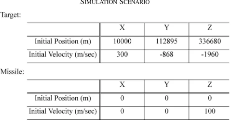
In numerical simulation, the feasibility of the presented ap-proach is satisfactorily demonstrated by the results of simula-tion scenario shown in Fig. 4. The total simulasimula-tion time of in-tercepting phase is 109.46 s, and the ZEM phase starts when the distance between the missile and the target is less than 100 m and lasts for only about 0.02 s. Finally, the shortest distance at the intercepting point is less than 1 m. The effect of the in-tercepting missile can be shown as in Fig. 4(a) and (b) since the lower velocity missile intercepts the ballistic missile with higher velocity after entering its reentry phase. The final velocity of the intercepting missile is 1230.6 m/s, which is almost one-third of
Fig. 4. Results of simulation scenario.
the velocity, 3168.6 m/s, of the target at the final time. On the other hand, the attitude tracking can be verified by the results of Fig. 4(c) and (d), which demonstrate successful tracking effects in terms of the quaternion angle and the sliding surface vari-able, respectively, for the rotation motion. From Fig. 4(e) and (f),
which show that a relatively larger value of control torque input occurs at the start during the entire flight phase of the missile, one can conclude that economical power consumption should be enough to complete the attitude tracking almost throughout the intercepting period. Finally, the plausible divert acceleration of DCS, less than , where is the gravitational acceleration, is shown in Fig. 4(g). In order to strengthen the applicability of the DCS actuator, we adopt a low-pass filter with bandwidth 5 Hz to limit the response performances of the actuator, and the desired force of the intercepting missile for the translation mo-tion remain realistic enough to achieve the satisfactory ballistic missile interception.
VII. CONCLUSION
The overall process of intercepting a ballistic missile gen-erally includes two parts: midcourse and terminal phases. In this brief, we focus on the overall phase composed of the above two phases of the interception, which is a period of time lasting until the ballistic missile is destroyed by the intercepting missile. Considering the properties of TVC, DCS, and nonideal conditions during the interception phase, we employed the controller incorporating variable structure based nonlinear missile guidance and autopilot systems, which can robustly adjust not only the missile attitude but also the translational dis-placement even under the conditions of model uncertainty and disturbances, such as variation of missile’s inertia, influence of aerodynamic force and unpredictable wind gusts. We respec-tively proved the stability of the individual guidance, autopilot and integrated systems via Lyapunov stability theory. Finally, after switch to ZEM phase, a bounded target interception can be achieved. A numerical simulation has been conducted to verify the feasibility of the integrated sliding-mode guidance and the autopilot systems with 5-DOF inputs.
TABLE I SIMULATIONSCENARIO
REFERENCES
[1] F.-K. Yeh, K.-Y. Cheng, and L.-C. Fu, “Nonlinear optimal sliding mode midcourse controller with thrust vector control,” in Proc. Amer. Control
Conf., 2002, pp. 1348–1353.
[2] L.-C. Fu, C.-W. Tsai, and F.-K. Yeh, “A nonlinear missile guidance con-troller with pulse type input devices,” in Proc. Amer. Control Conf., 1999, pp. 3753–3757.
[3] I. Ha and S. Chong, “Design of a CLOS guidance law via feedback lin-earization,” IEEE Trans. Aerosp. Electron. Syst., vol. 28, pp. 51–63, Jan. 1992.
[4] J. Huang and C.-F. Lin, “A modified CLOS guidance law via right in-version,” IEEE Trans. Aerosp. Electron. Syst., vol. 31, pp. 491–495, Jan. 1995.
[5] B. Wie, H. Weiss, and A. Arapostathis, “Quaternion feedback regulator for spacecraft eigenaxis rotations,” J. Guid. Control Dyn., vol. 12, no. 3, pp. 375–380, 1989.
[6] Y.-P. Chen and S.-C. Lo, “Sliding-mode controller design for spacecraft attitude tracking maneuvers,” IEEE Trans. Aerosp. Electron. Syst., vol. 29, pp. 1328–1333, Oct. 1993.
[7] S.-C. Lo and Y.-P. Chen, “Smooth sliding-mode control for spacecraft attitude tracking maneuvers,” J. Guid. Control Dyn., vol. 18, no. 6, pp. 1345–1349, 1995.
[8] J. J. E. Slotine, “Sliding controller design for nonlinear systems,” Int. J.
Control, vol. 40, no. 2, pp. 421–434, 1984.
[9] J. Moon, K. Kim, and Y. Kim, “Design of missile guidance law via variable structure control,” J. Guid. Control Dyn., vol. 24, no. 4, pp. 659–664, 2001.
[10] D. Zhou, C. Mu, and W. Xu, “Adaptive sliding-mode guidance of a homing missile,” J. Guid. Control Dyn., vol. 22, no. 4, pp. 589–594, 1999.
[11] R. Resnick and D. Halliday, Physics, 4th ed. New York: Wiley, 1992, vol. 1.
[12] P. Zarchan, Tactical and Strategic Missile Guidance, 2nd ed. Washington, DC: American Institute of Aeronautics and Astronautics, Inc., 1990, vol. 157.