Automatic feature point extraction on a human
face in model-based image coding
Ho-Chao Huang Ming Ouhyoung Ja-Ling Wu
National Taiwan University
Department of Computer Science and Information Engineering
Taipei 10764, Taiwan
1 Introduction
Thevideo phone or video conference has become one of the most popular video applications on ISDN and other service networks. In these applications, the human face is the major component of communicated video, and the capability of the video compression algorithms for dealing with the human face will effect the video quality significantly. Most moving picture coding algorithms such as the Moving Picture Experts Group (MPEG) and H.261, which have been used widely in existing video phone systems, use the motion compensated/ discrete cosine transform (MCIDCT)based coding algorithm, but this general purpose coding scheme cannot deliver high— quality images under very low bit rate constraints.
In Ref. 1 the model-based image coding (MBIC) was proposed. In previous research, the model for a human face was established,2 and the MBASIC system, which is designed to compress the image data for a human face, was proposed in Ref. 3. The MBASIC system separates the face region from the background image, points out the feature points of outline and expressions of the face, and synthesizes the human face by adjusting the existing 3-D facial model with these feature points.
Paper VCI-02 received Sep. 21, 1992; revised manuscript received Jan. 31, 1993; accepted for publication Feb. 16, 1993.
1993 Society of Photo-Optical Instrumentation Engineers. 0091-3286/93/$2.OO.
Abstract. A preliminary version of a feature point extractor is proposed. In existing model-based coding systems, the feature points of the human face are extracted manually. To make model-based image coding more practical, a coder that can automatically extract the feature points must be developed. We define an ideal feature point extractor and discuss both the requirements and problems. A preliminary solution has been implemented. The proposed feature point extractor can automatically ex-tract the feature points of eyebrows, eyes, the outline of a face, and some other useful information. It can be combined with model-based image coding and used in the video phone/conference systems.
Subject terms: visual communication; automatic feature point extraction; computer
graphics; data compression; image coding; video coding. OpticalEngineering 32(7), 1571—1580 (July 1993).
Althoughthe MBASIC has the great potential of com-pressing image data at a very low bit rate with good picture quality, many problems still exist. One of the major problems of MBASIC is that the feature points can hardly be extracted
automatically from the input image. In most existing
MBASIC systems, these feature points are extracted
manually4 or pointed out by spots or indicators.5 These meth-ods are not reasonable solutions for the video phone system because the coder of this system must compress the video automatically in real time. To make the MBASIC practical, automatic extraction of the feature points is a must.
In this paper, a preliminary version of a feature point extractor (FPE) is proposed. An FPE can automatically find the positions of feature points, such as the ends of eyebrows, eyes and mouth, as well as the outline pointsof a face, from an input image. From our experiments and with some rea-sonable assumptions, the proposed version of FPE can find the end points of eyebrows and eyes with relatively high percentages of correctness (about 87%) and estimate the po-sition and shape of the mouth and the outline of face with fairly good accuracy. Combining MBASIC with this new FPE greatly increases its practicability.
The paper is organized as follows. The outline of MBASIC is first reviewed in Sec. 2. Section 3 addresses the require-ments and the desired functions of an ideal FPE. The algo-rithm of the proposed preliminary version of FPE is given in Sec. 4, and some corresponding experimental results are
E6ckTr"",
Image
Analysis Synthesis
Parameters
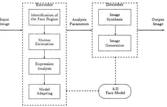
Fig. 1 Block diagram of human face model-based image coding system.
shown in Sec. 5.Finally, Sec. 6 gives the conclusions and the direction of future works.
2
Review of Human Face MBASICIn the facial MBASIC system,3 both the encoder and the decoder contain a 3-D wire frame facial model, which rep-resents a general human face from about 400 up to 3000 triangles. The encoder (see Fig. 1) analyzes the input image by separating the face region from the background image, estimating the motion of the person's face and analyzing the facial expressions. The encoder transmits the analyzed pa-rameters that will be received by the decoder to adjust the 3-D facial model, then synthesizes and generates the output image. The residual signal of the original image and the reconstructed image is then coded, transmitted, and
recon-structed by a wave-form coder.4
Theproblem of feature point extraction. To adjust the
generalhuman face model to fit the face obtained from the input image, some feature points of the human face, such as the end points of eyebrows, eyes, and mouth, as well as the control points on the outline of face, must be identified first. There are two conventional strategies for extracting the fea-ture points:
Strategy I: extracting feature points manually
In some existing MBASIC system such as model-based! wave-form hybrid coding,4 the strategy of feature extraction is as follows. In the leading image of the sequence, feature points are extracted manually. The points are roughly tracked by block matching in the succeeding frames. Templates of eyebrows, eyes, and the mouth of the past frames are used for this block matching.
Strategy
II: tracking feature points by bright spotsInanother model-based coding system, the so-called facial 1572/OPTICALENGINEERING/July 1993/Vol. 32 No.7
animation,5 the luminance of the input image is suppressed and the feature points are tracked by small round adhesive spots from the tape on a face. The problem of extracting feature points of a human face becomes tracking the bright spots in a dark environment.
Bothmethodsdescribed above are not suitable solutions of MBASIC for video phone and video conference. In a video phone, the video encoder is expected to compress the input image within 1/30 to 1/8 s without any manual operation. The other workable approach for extracting the feature points is to paste some conspicuous tapes on the faces of the people using the video phone. Although this method is considered to be a convenient and effective way to solve the problem of feature point extraction, it is quite impolite, actually, im-possible, to ask users like managers of companies to stick
some tapes on their faces during the meeting. Therefore, the taping is only an experimental skill but not a practical so-lution. Because of the drawbacks of the existing techniques mentioned above, it seems necessary and useful to develop a new skill for the automatic feature point extraction, to make the MBASIC for real-time video applications practical. This
fact motivates our work.
3 Ideal FPE and its Problems
To design a feasible FPE, we must define the functions we want the FPE to have, to understand the characteristics of input images and to realize what problems will be encoun-tered during the development of the FPE.
3.1 The Ideal FPE
The basic functions of an ideal FPE are:
1 . Separatingthe face region from the background image. In most situations, the input image contains not only the user' s face but also some background objects. The
Eri&kkir
: Identificationof
Input : theFace Region
Image I Output Image I. J I 3-D
r
I FaceMoaeideal FPE must separate the human face from the back-ground image so that the operations of following func-tions can be isolated from the interferences caused by these irrelevant objects.
2. Scratching the outline of the human face and pointing out the control points of the face' s shape.
The next function of FPE is to find the contour of the human face. Because the face region found by the pre-vious function may be noisy, the FPE needs a special low-pass filter to smooth the contour.
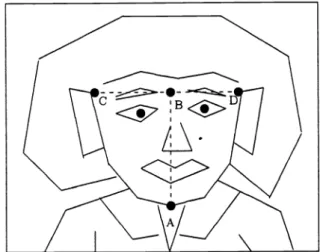
After the outline of the face is found, the FPE is able to identify the control points (see Fig. 2) of a face's shape such as the center points of the lower jaw (A) and brows (B) and the positions of the temples (C) and (D).Theline segment AB defines the length and di-rection of the human face' s major axis, and the width of head is defined by the length of line segment CD. 3. Finding the sense organs, including the eyebrows, eyes,
ears, nostrils, and mouth.
When the region and direction of the face are deter-mined, it is possible to find the sense organs, such as the eyebrows, eyes, ears, nostrils, and the mouth, which are the major components of the general human model. 4. Extracting the feature points and expression parameters
of the face.
The most important function of FPE is to extract the feature points. The end points of eyebrows and eyes, the width of nostrils, heights of ears, and shape of mouth are all the important information that the coder can use to catch the expression of the user and recon-struct a lifelike image. Figure 3 shows the desired fea-ture points that must be extracted by FPE.
The basic requirements of an ideal FPE are: 1. Automatic execution.
As discussed in the previous section, the MBASIC for real-time video applications does not allow manual process. All functions must be done automatically. 2. User independent.
An ideal FPE is expected to extract the correct feature points regardless of who is using the MBASIC system; even though all the facial features, such as the facial width-to-length ratio, the size, shape, and symmetry of sense organs, and the color and luminance of the face, are user dependent.
3. Environment independent.
An ideal FPE must separate the face from the ground image regardless of the objects in the back-ground image, the direction of the user' s face, the po-sition of the user's face in the input image, and the distance from the user to a camera. The FPE must also recognize the sense organs from the user's face even if the user wears glasses, is bearded, and so on.
3.2
The Problems of an Ideal FPEThe desired functions and basic requirements of the ideal FPE have already been stated above. Many challenges must
Fig. 2 The control points of a human face, A and B are the center points of lower jaw and brows, respectively, C and D are the tem-AB defines the length and direction of major axis of face, and CD defines the width.
Fig. 3 The feature points of a human face.
be faced when developing the FPE:
1 . Itis difficult to separate the face from the background image clearly. In most cases, some chrominances and luminances of background objects around the user's head are close to those of the human face. To differ-entiate those objects from the outline of a face is not easy.
2. Eventhough the region of a human face can be clearly separated, the sense organs may not all appear in the input image because the user may not face the camera directly, or some objects such as the eyebrows and the mouth may be covered by hair, glasses, or a beard. It is hard to define the objects that are partially visible on the input image.
3. Evenif the objects are all shown on the image, their control points or feature points cannot be easily found by a simple extraction algorithm. The shape of a mouth and the outline of a lower jaw, for example, are not clearly identified in most images.
4. Theface may be segmented by some other objects, such as sunglasses. In this case, the complete region of a face can hardly be obtained.
5. The brightness, contrast, and the chrominance of the face may change from image to image. It is not easy to get the characteristics of the feature points.
4
The Preliminary FPETheproposed preliminary FPE (PFPE) is addressed in this section. To solve the problems listed above, we made some reasonable assumptions as to the necessary conditions of the input image.
1. Theuser' s face must appear at about the center of the input image.
2. The area ofthe user' s face must be atleast one-sixteenth the size of the input image. (The reason to choose the size is that in video conferencing, the human's face is the major component of the input image. Thus, we assume the user' 5 face will occupy at least one sixteenth the size of the input image, and to reduce the interfer-ence of other objects, we do not choose a larger size.) 3. The eyebrows, eyes, and mouth must be visible. 4. The user cannot wear sunglasses or glasses with a black
frame.
5. The angle of the major axis and the perpendicular line of the user's face cannot be greater than 90 deg. In practical uses, assumption 1 is only needed in the first frame of the video, the central point of the human's face in the second frame can be obtained by calculating the central point of the found human's face in the first frame, and the central points of the subsequent frames can be iteratively found in the same way. Under these assumptions, which are justified in most video conference applications, the design
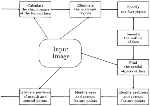
and development of a FPE are no longer far from possible. The flowchart of the PFPE is shown in Fig. 4.
4.1 Preprocessor: Calculating the Chrominance and Luminance of a Human Face
First,the average chrominance and luminance of the center area of the input image are calculated as those of a human face. Under assumptions 1 and 2, the selected area is 1/16 of the input image size, and is shown in Fig. 5.
The chrominance and the luminance of the human face Cface are defined, respectively, as:
1
C(n),
Cface —
the size of selected area n Eselected area (1)
1574/OPTICAL ENGINEERING/July 1993/Vol. 32 No.7
Fig. 4 The flowchart of the PFPE.
I
I-Selected Area Center PointHtH
tT
1'I
Fig. 5 The selected region of the input image for calculating the chrominance of the human face.
u-w
flIHIIIiTiTi
(a)
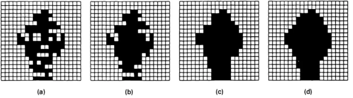
Fig. 6 The examples of the execution results of the processes: specifying the face region and smooth-ing the outline of the face: (a) the original largest objects, (b) the same object after fillsmooth-ing the holes inside it, and (c) and (d) the results of the largest object after the fill-up process and the low-pass filter of the smoother, respectively.
1
L(n),
Lface —the size of selected area n selected area (2) where the C(n) and L(n) are the chrominances and luminances of the original pixels. The Cface 5 used by the eliminator (see Sec. 4.2) and the Lface 5 then referred by the object finder (see Sec. 4.5) to specify the special objects.
4.2 Eliminator: Eliminating the Irrelevant Regions
Whenthe chrominance of face is calculated, defined as Cface, the threshold THCf 5 also determined. We assume that the pixels with the chrominances between Cface THCface and Cface + THCf are the candidate pixels of the face. The pixels with the chrominance values outside this range are elimi-nated.
Let C(n) be the chrominances of the original pixels, then the output pixels' chrominance values C(n) are defined as:
I Cface if Cface THCf C(n) Cface + THCf C(n) =
lo
otherwiseThe reason for using the chrominance as the reference instead of the luminance is that the luminances of pixels on the face may change drastically, caused by the lighting and geometry. Although both the luminance and chrominance are the linear combinations of RGB components, the experiments show that the homogeneity of the chrominances of the pixels of the face is higher than that of the luminances.
4.3 Face-Finder: Specifying the Face Region
After the irrelevant regions are eliminated by the previous
process, some objects with chrominances similar to that of the human face are retained in the image. Under assumption 2 of PFPE, the face region occupies at least one-sixteenth of the image. Therefore, the largest object that contains the larg-est amount of adjacent pixels is selected as the human face. The largest object usually contains a large number of holes as shown in Fig. 6(a). The FPE must draw the outline of the object and fill the holes inside the largest object. The result of this process is shown in Fig. 6(b).
4.4 Smoother:
Smoothing the Outline of a FaceTheoutline of the human face is usually a highly noisy con-tour. The smoother, which smoothes the outline of the face, contains two functions: (1) the ''fill-upprocess' 'and(2) the "low-pass filter," to eliminate this noise.
The fill-up process uses a special function to fill up the hollows of the contour. The fill-up function is defined as: £(n) = min[ max X(n —i), max X(n + i)1
OazWSfi OzWSfi4 (4)
where WS is the window size for the fill-up process, X(n) is the x or y component of the n'th pixel of the original contour, and the X (n) is the output contour signal.
When the holes have been filled up, the outline of the face is then smoothed by a low-pass filter; that is,
(n)=[X(n—2)+3X(n—1)+3X(n)+X(n+1)I
(5)Examples of the results performed by the fill-up process and the low-pass filter are shown in Figs. 6(c) and 6(d), (3) respectively.
4.5
Object-Finder: Finding the Special Objects ofa Face
Afterexecuting the smoother, we find the face region; then we can focus on the face region to search for the special objects on the face. To recognize these special objects, the special areas are specified as the candidates of special objects by the following function:
2Lface3
Oj(n) = OscL(n)sc— n a selected area (6)
where if 5 equal to one iff is true and equal to zero iff is false, L(n) is the luminance of the pixel X(n), and the Oj(n) is set to one if the pixel X(n) is in the face region and its luminance is less than or equal to 2/3 times that ofthe selected area defined in the preprocessor.
Under our experiments, the luminances of the special ob-jects such as the eyebrows, eyes, nostrils, and mouth are darker than that of the face region, thus, we select the pixels
max
Oj(n)e object set and S[Oj(n)JS[Oj(HEB)]
1576/OPTICALENGINEERING/July 1993/Vol. 32 No.7
wherefh is definedas: T(CHEBCLEB).
CHEBCQf(fl) X S[Oj(n)] X 20
fh=
ICHEBCOI(fl)3ICHEBCLEB
and
lower eye=Oj[idx( max
Oj(n)eobject set and S[Oj(n)IS[Oj(LEB)]
wheref1 is defined as:
T(CHEBCLEB). CLEBCQJ(fl) X S[Oj(n)] X 20
fi = ICLEBCOI(fl)3ICIEBCLEBI I 01 D 02
__________________
E B zz:::I:III:;:I::I::::: (10)\::.I.IIIIII:\04
03f1
___________________ (11)Fig.7 Typical special objects found by the object finder.
(12) whose luminance is much smaller than that of the face region.
The adjacent pixels X(n) with Oj(n) equal to one are then
grouped into the same special object. Because of the effect where T(i) is the function that exchanges the x and y com-caused by the smoother, some darker areas such as the hair ponents of the segment ,andf. g denotes the inner product may be included in the face region, thus, decreasing the cor- of the vectors f and g.
rectness of the following function. Therefore, the special The functions to find the feature points of the eyes are areas next to the boundary of the face region are deleted from similar to those in the eyebrow finder and are omitted here. the list to eliminate the side effect of the smoother.
4.8 Estimator: Estimating the Positions of the 4.6 Eyebrow-Finder: Identifying Eyebrows and Mouth and Nostrils, and the Control Points of a
Extracting their Feature Points Face'5 Outline
Underassumption 5, at least one of the eyebrows will be the The final function of PFPE is the estimator, which can es-highest special object found by the object finder. After elim- timate the positions and draw the shapes of the mouth and mating the objects with a size less than a threshold THspecjai, nose and the control points of the outline of the user' s face. the higher eyebrow can be found by the function: The position of the mouth is below the eyes, and at a distance from the eyes of about two to four times that from higher eyebrow =Oj{idxmax[height of Oj(n)]} , (7) the eyes to eyebrows. In general, the shape of the mouth varies greatly and we cannot use it to assist the PFPE to find where the idx(g) returns the index number ofthe special object the mouth. The nostrils are located between the eyes and
with the height equal to g. mouth, and near the mouth. It is not difficult to find them
Once the higher eyebrow is found as shown in Fig. 7, we and draw their shapes.
can find the two pixels A and B such that the distance A is Finally, the estimator needs to find the control points of the largest among all pixel pairs within the higher eyebrow. the outline of a face. The face region has been already spec-The other feature points D and E can also be found by search- ified in the face finder, and the major axis of the face is ing for the pixel pairs whose distance is the longest and the normally parallel to the perpendicular bisecting lines of the angle betweenAi and Z is about 90 deg. Finally, the higher eyes and eyebrows. With this information, the control points eyebrow is eliminated from the set of the special objects. of the face can be found easily. The procedure to perform
The second eyebrow, lower eyebrow, is defined by: the functions of the estimator described in this subsection is still under development.
LEB =Oj{idx[maxS(OJ(fl))!S(HEB)Icos(LC,lCHEBA)I]} (8)
5
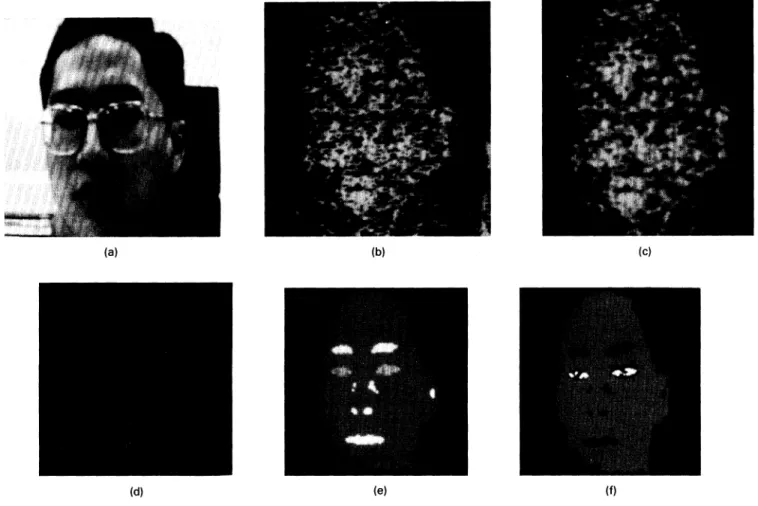
Experimental ResultswhereHEB is higher eyebrow, S(O) is the size of the object Several experimental results are shown in this section. In 0, C, is the center point of the object Oj(n), and the term these experiments, the THCface S fixed at five by practice. LEB will be used in the following to replace the term lower Figure 8(a) shows the input image captured by a camcorder,
eyebrow. and the format of pixels is shown in Fig. 9; Fig. 8(b) shows
The feature points of the LEB can be found by the same the result performed by the eliminator; Fig. 8(c) is the output algorithm that was used to find the feature points of the HEB, image of the face finder; Fig. 8(d) is the resultant image of and the LEB is then deleted from the set of special objects. the smoother, where WS is set at 20; Fig. 8(e) shows the objects found by the object finder, eyebrow finder, and eye 4.7 Eye-Finder: Identifying Eyes and Extracting finder with THspeciaiequalto 10 pixels; and finally,Fig. 8(f)
their
Feature Points shows the example of pasting theeyebrows and eyes by usingFollowing the eyebrows, the eyes of the user' s face can be the feature points found by the PFPE on the user' s face region found by the eye finder. The functions to find the user' s eyes that is also found by the PFPE.
are: In this experiment, the user wears a pair of glasses with
a silver border; The PFPE can find the feature points of
higher eye = Oj[idx( eyebrows and eyes, and scratch the outline of the user' s face
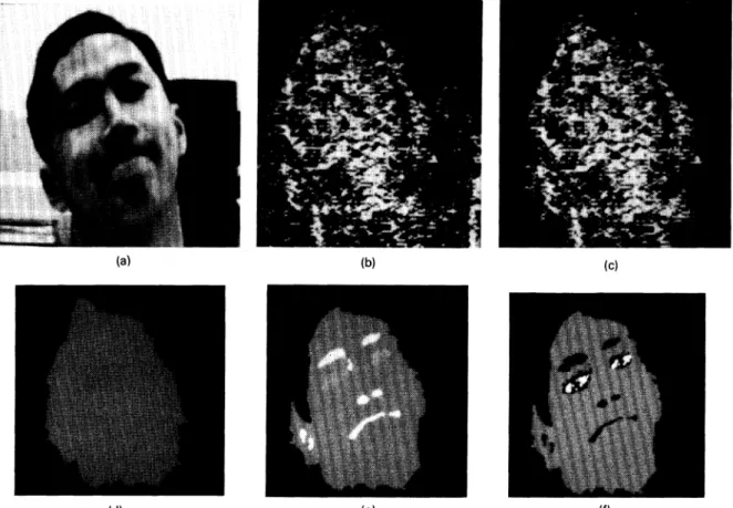
correctly. The resultant images of the second experiment, (9) wherethe user makes grimaces, are shown in Fig. 10. Figure
Fig. 8 The resultant images of PFPE with the user wearing a pair of glasses with silver border.
Pixel
bit no. 15 14 10 9
54
0Fig. 9 The format of an input pixel: the red, green, and blue signals have 5 bits, respectively, and the 15th bit is unused.
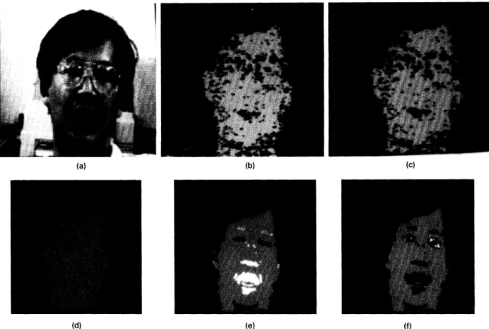
1 1 , thethird set of resultant images, shows a bearded user making grimaces. Finally, Fig. 12 shows the resultant images where the user is bearded and wears a pair of glasses. In all these experiments, the PFPE can do all tasks well.
The execution time of each function unit of the PFPE is listed in Table 1, the PFPE was executed on a PC/486-33 with a MS-DOS 5.0operationsystem and written in Borland
C++ 3.0 language; and the size of input image was
128x
128.From our experiments and the assumptions stated in
Sec. 4, the face regions in the input images can usually be found correctly. The positions and feature points of eyebrows can be extracted with about 95%correctness, and those of eyes can be extracted with about 70% correctness. The overall percentage of correctness for finding the feature points and face regions is about 87%.
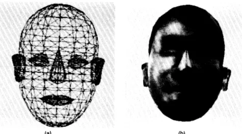
After the feature points of the human face have been found by the PFPE, the MBASIC system could use them to adjust the wire frame model and synthesize a human face using the texture mapping technique.6 The examples of the wire frame facial model and the synthesized textured image, which are obtained from the result of Ref. 7, are shown in Fig. 13.
In the wire frame model, special objects, such as eyes, eyebrows, nose, mouth, and ears, are isolated from the face. A bounding box (or polygon) for each special object can be obtained by using the feature points extracted by the proposed system. Then the wire frame model of the object is translated, rotated, and scaled by dynamic programming to fit the bound-ing box. Finally, a texture-mappbound-ing technique is used to shade the human's face. This method has been used successfully in the "hair-styling" project in our laboratory.
When feature extraction fails, the proposed system does
(a) (b) (c)
(d) (e) (f)
1578/OPTICAL ENGINEERING/July 1993/Vol. 32 No.7
I
Fig. 10 The second set of resultant images from PFPE in which the user grimaces.
(d) (e) (f)
Fig. 11 The third set of resultant images performed by the PFPE. In this example the user is bearded and grimaces.
Fig. 12 The final set of resultant images performed by the PFPE. In this example, the user is bearded
nothing about it. However, in a real video coding system, the hybrid coding method proposed in Ref. 4 should be used. In the hybrid system, the error caused by the extraction failure can be compensated by using the wave-form coding tech-niques.
6 Conclusions and Future Works
In previous sections, we first introduced the existing problem of the MBASIC system, the feature point extraction problem, and list the problems ofexisting feature point extraction strat-egies. These problems make the MBASIC system far from practical and need to be solved.
In this paper, an ideal feature point extractor (FPE) was designed to solve the feature point extraction problem men-tioned above. The basic functions and requirements of the ideal FPE, which can automatically extract the feature points of a user' s face in the input image, are defined, and the problems on developing the ideal FPE are also listed.
A preliminary version of the FPE (PFPE) was developed and described in this paper. The PFPE can automatically search the feature points and control points of the user's face in the input image under some reasonable assumptions. As our experiments show in this paper, the PFPE can find the feature points of the eyes and eyebrows and the outline of the face with a high degree of correctness even though the user wears a set of glasses, makes grimaces, and does not look at the camcorder directly.
Since the automatic feature point extraction is a new re-search topic in MBASIC, the PFPE is not a complete solution yet. Many things need to be done, such as extracting the detail expressions and searching for all feature points without the limitations set by the PFPE. The development of the next version of FPE is our future work.
All the values of the parameters, such as THCface WSfU, and THspeciai, used in the PFPE are determined from exper-iments. Because the performance of the PFPE sensitively depends on these parameters, a systematic algorithm to adjust the values of these parameters may be useful and remains as a future work.
Furthermore, the FPE must be combined with the
MBASIC system for practicaluse. The integration ofthe FPE, modeling and synthesis processes including the texture-mapping technique, is also part of our future work.
Finally, as pointed out by one of the anonymous referees, the main advantage of the proposed system is its practica-bility, in other words, the proposed system provides a simpler, faster, and more reliable feasible solution to the feature point extraction problem than the previous related works given in Refs. 1—5, 8, and9.
Acknowledgment
Theauthors wish to thank the anonymous referees for their valuable comments and suggestions. This work is supported by the National Science Council, Taiwan, under grant num-bers NSC8 1-0408-E-002- 14 and NSC8 1 -0408-E-002- 16.
(d)
and wears glasses.
Table 1 The execution time of each function unit in PFPE. The PFPE was executed on a PC/486-33 with an MS-DOS 5.0 operating
system and written in Borland C ++ 3.0language; and the input image size was 128x 128.
FUllCtiOfl Unit Execution time (ms/frame)
Preprocessor 0.4 Eliminator 58.7 Face-Finder 129.6 Smoother 36.0 Object-Finder 134.3 Eyebrow-Finder 117.8 Eye-Finder 71.4 Total 548.2 References
1. K.Aizawa, H. Harashima, and T. Saito, "Model-based synthetic image coding," Picture Coding Symp. (PCS's 87), pp. 50—51, 9—1 1 June 1987, Stockholm, Sweden.
2. K.Aizawa, T. Saito, and H. Harashima, ''Constructionof a 3-dimensional personal face model for knowledge-based image data compression,' 'Nat.
Conf Record IEICEJ, pp. 1—221, 3—6 September 1986, Musashino, Ja-pan.
3. K. Aizawa, H. Harashima, and T. Saito, ''Model-basedanalysis synthesis image coding (MBASIC) system for a person's face,' ' Sig. Process.
Image Commun. 1(2), pp. 139—152 (October 1989).
4. Y. Nakaya, Y. C. Chuah, and H. Harashima, "Model-based/waveform hybrid coding for videotelephone images," iEEE mt. Confi Acoust. Speech Sig. Process. ICASSP-91, 2741—2744(May1991).
5. L. Williams, ''Performance-drivenfacial animation,' 'Comput.Graph. 24(4),235—242 (August 1990).
6. K. Waters and D. Terzopoulos, ''Modelingand animating faces using scanned data," J. Visual. Comput. Anim. 2, 123—128 (1991).
7. F. Liao, ''Designand implementation of facial texture mapping,' ' NTU
CSIE Term Project Report, unpublished (June 1992).
8. T. S. Huang, S. C. Reddy, and K. Aizawa, "Human facial motion mod-eling analysis and synthesis for video compression,' ' inVisual Corn-rnunications and Image Processing '91: Visual Cornrnunication, Proc. SPJE1605, 234—241 (1991).
9. M. Kaneko, A. Koike, and Y. Hatori, ''Codingof facial image sequence
based on a 3-D model of the head and motion detection,' 'J. Visual Cornrnun. Image Represent. 2(1), 39-54 (1991).
Ho-Chao Huang received the BS degree
from the Department of Computer Science and Information Engineering at the Na-tional Taiwan University, Taipei, in 1990. He is now a PhD student there. His re-search interests include variable-length codes, software-based video data compression, model-based image coding, computer networks, computer graphics, graphics user interface, and multimedia systems. Huang is a student member of
IEEE.
Ming Ouhyoung received the BS and MS degrees in electrical engineering from the
National Taiwan University, Taipei, in 1981
and 1 985, respectively. He received the PhD degree in computer science from the University of North Carolina at Chapel Hill
in 1990. He was a member of the technical
staff at AT&T Bell Laboratories,
Middle-town, during 1990 and 1991 . Since August 1 991 , he has been an associate professor intheComputer Science and Information Engineering Department, National Taiwan University. He has pub-lished papers on signal processing and computer graphics. He is currently engaged in research in the areas of computer graphics,
virtual reality, and multimedia systems. He is a member of ACM and IEEE.
Ja-Ling Wu received the BS degree in electronics engineering from the Tamkang
University, Tamshoei, Taiwan, in 1979 and
the MS and PhD degrees in electrical en-gineering from Tatung Institute of Tech-nology in 1981 and 1986, respectively. From 1 986 to 1 987 he was an associate professor in the Electrical Engineering De-partment at Tatung Institute of Technol-ogy, Taipei, Taiwan. Since 1987 he has been with the Department of Computer Science and Information Engineering, National Taiwan University, where he is presently a professor. Dr. Wu was the recipient of the 1989 Outstanding Youth Medal of the Republic of China and the Outstanding Research Award sponsored by the National Science
Council from 1987 to 1992. He has published more than 100 papers.
His research interests include neural networks, VLSI signal pro-cessing, parallel propro-cessing, image coding, algorithm design for DSP, data compression, and multimedia systems.
1580/OPTICAL ENGINEERING/July 1993/Vol. 32 No.7
(a) (b)