國 立 交 通 大 學
機 械 工 程 學 系
博 士 論 文
新型腰椎獨立式融合器的生物力學分析
Biomechanical Analysis of A New Stand-alone Lumbar Cage
研 究 生:江銘傑
指導教授:洪景華 教授
新型腰椎獨立式融合器的生物力學分析
Biomechanical Analysis of A New Stand-alone Lumbar Cage
研 究 生:
江銘傑
Student: Ming-Chieh Chiang
指導教授:
洪景華
Advisor: Ching-Hua Hung
國 立 交 通 大 學
機械工程學系
博 士 論 文
A Thesis
Submitted to Department of Mechanical Engineering
College of Engineering
National Chiao Tung University
in Partial Fulfillment of the Requirements
for the Degree of
Doctor of Philosophy
in
Mechanical Engineering
November 2013
Hsinchu, Taiwan, Republic of China
i
新型腰椎獨立式融合器的生物力學分析
研究生:江銘傑 指導教授:洪景華 教授國立交通大學機械工程學系
摘 要
腰椎間盤退化和其所引發的各種併發症是目前世界常遭遇的脊椎病變之一,其治療 方式分為保守與手術治療,其中,腰椎間融合術是手術治療方式之一,其方法是清除發 生病變的腰椎間盤,再將自體或異體骨植入,且合併使用椎間融合器,以達到去除病源、 提供穩定脊椎、避免神經壓迫等治療效果。研究指出,在前腰椎融合術(Anterior lumbar interbody fusion, ALIF)單獨使用融合器,無法提供脊椎在後彎動作下足夠的穩定性,必須搭配後位內固定器才能有良好穩性效果,達成椎間融合的目的。但植入後位內固定器 需增開後方傷口,會損壞肌肉血管組織甚至傷及脊神經。因此,一種具備自我穩定能力 的獨立椎間融合器(Self-stabilizing stand-alone fusion cage)設計發展出來,期望透過特殊 的幾何設計,在融合手術時無需搭配後位內固定器就能達成椎間融合的融合效果。
本研究利用一個經過驗證的五節腰椎有限元素模型,在施加伴隨負荷(Follower load) 的情形進行分析,共分為兩個部分,第一部分進行三款 Self-stabilizing stand-alone cage: 新型 Latero 融合器,與兩種舊有的 ALIF 融合器(SynFix,Stabilis),對比傳統 ALIF 融 合器搭配後位內固定器的穩定效果比較,並藉由多種生物評估參數包括:穩定性、環帶 應力、小面關節受力以及植入物應力,來探討三款 Stand-alone 融合器的椎間穩定度與 此三種融合器對於腰椎界面造成的影響。第二部分則對 Latero 融合器提出後續設計建議 並加以分析。 本研究第一部分結果發現,新型 Stand-alone 融合器 Latero 的穩定效果相似於和傳 統 ALIF 融合器搭配後位內固定器,若在考量避免增開後方傷口對病患造成影響的情形 下,建議使用 Latero 融合器,就可提供腰椎間足夠的穩定性與適合融合的環境。第二部 分結果則提出針對 Latero 融合器的後續設計建議。 關鍵字: 前位融合; 獨立式融合器;有限元素分析。
ii
Biomechanical Analysis of A New Stand-alone Lumbar Cage
Student: Ming-Chieh Chiang Advisor: Prof. Ching-Hua Hung
Department of Mechanical Engineering
National Chiao Tung University
ABSTRACT
For anterior lumbar interbody fusion (ALIF), stand-alone cages can be supplemented
with vertebral plate, locking screws, or threaded cylinder to avoid the use of posterior fixation.
Intuitively, the plate, screw, and cylinder aim to be embedded into the vertebral bodies to
effectively immobilize the cage itself. The kinematic and mechanical effects of these
integrated components on the lumbar construct have not been extensively studied. In the
part-1 of this study, a nonlinearly lumbar finite-element model was developed and validated to
investigate the biomechanical differences between three stand-alone (Latero, SynFix, and
Stabilis) and SynCage-Open plus transpedicular fixation. All four cages were instrumented at
the L3-4 level. In the part-2 of this study, the Latero was analyzed for different design
parameters.
The lumbar models were subject to the follower load along the lumbar column and the
moment at the lumbar top to produce flexion (FL), extension (EX), left/right lateral bending
(LLB, RLB), and left/right axial rotation (LAR, RAR). A 10 Nm moment was applied to
obtain the six physiological motions in all models. The comparison indices included disc
ROM, facet contact force, and stresses of the annulus and implants.
At the surgical level, the SynCage-open model supplemented with transpedicular fixation
decreased ROM (>76%) greatly; while the SynFix model decreased ROM 56-72%, the Latero
iii
Stabilis model decreased ROM slightly in extension (11%), lateral bending (21%), and axial
rotation (34%). At the adjacent levels, there were no obvious differences in ROM and annulus
stress among all instrumented models.
ALIF instrumentation with the Latero or SynFix cage provides an acceptable stability for
clinical use without the requirement of additional posterior fixation. However, the Stabilis cage
is not favored in extension and lateral bending because of insufficient stabilization.
iv
誌 謝
首先要衷心地感謝指導教授洪景華老師,願意耗費許多時間教導學生,使學生遭遇 研究瓶頸時,不僅能迎刃而解,且能適時給予信心與鼓勵,引導學生培養獨立研究的態 度與創新構想的思維,讓學生盡情的發揮。 特別感謝陳世豪醫師、林君甫醫師以及林上智教授,在研究上提供了專業智識與寶 貴建議。 感謝廖建忠博士、陳振昇教授、林上智教授、楊秉祥教授、林君甫醫師在百忙之中 挪出時間參加學生口試給於意見,讓學生的論文更加完整。 回首研究所期間,特別感謝實驗室政成學長、正展學長,在遇到困難時,適時剖析 建議與協助;感謝研究室夥伴在學業及生活中的指導與關懷,特別是實驗室生醫組的同 學,在研究生涯中的陪伴,所建立的深厚友誼與每一句歡笑將成為美好的回憶。期間, 也受到交大機械所許多師長、助教的教導與提攜,同樣致上最誠摯的謝意。 最後,僅以此論文獻給我最敬愛的雙親與家人,感恩他們多年來不辭辛勞的養育、 栽培與無怨無悔的付出。 作者:江銘傑 謹誌 中華民國 102 年 11 月v
Table of Contents
Chapter 1 Introduction ... 1
1.1. Overview ... 1
1.2. Motivation and objectives ... 1
1.3. Outline ... 3
Chapter 2 Background ... 5
2.1. Spine anatomy and biomechanics ... 5
2.1.1. Vertebra ... 7
2.1.2. Intervertebral disc ... 8
2.1.3. Facet joint ... 9
2.1.4. Spinal ligaments ... 10
2.1.5. Neural foramen ... 11
2.1.6. Spinal cord and nerve roots ... 11
2.2. Spinal pathology and treatments ... 12
2.2.1. Lumbar spinal stenosis... 13
2.2.2. Conservative therapy ... 16
2.2.3. Decompression surgery ... 17
2.2.4. Fusion surgery ... 18
2.2.5. Lumbar interbody fusion cages ... 21
2.2.6. Minimally invasive techniques and stand-alone implant ... 23
Chapter 3 Materials and Methods ... 26
3.1 Part-1 of this study ... 26
3.1.1. The establishment of intact lumbar spine model (INT model) ... 26
3.1.2. The establishment of implant models ... 40
vi
3.2.1. The different insert positions of Latero model... 46
3.2.2. Different angle of the lateral plate of the Latero ... 47
3.3. Boundary and loading conditions ... 49
Chapter 4 Results ... 51
4.1. Part-1 ... 51
4.1.1. ROM ... 51
4.1.2. Annulus stress ... 54
4.1.3. Facet contact force ... 57
4.1.4. Implant stress ... 59
4.1.5. Endplate stress ... 61
4.2. Part-2 ... 62
4.2.1. ROM of different positions ... 62
4.2.2. ROM of different lateral plate angles ... 64
Chapter 5 Discussion ... 66
5.1. Part-1: Comparison with stand-alone implants and conventional fixation method ... 66
5.1.1. ROM ... 66
5.1.2. von-Mises stress at the vertebra ... 68
5.1.3. Facet contact force ... 69
5.1.4. Stress distribution at the annulus ... 70
5.2. Part-2: The effects of different design factors for Latero device ... 70
5.3. Limitations ... 71
Chapter 6 Conclusion and Future Work ... 73
6.1 Part-1: Conclusion ... 73
6.2 Part-2: Conclusion ... 74
vii
References ... 76 Vita... 88
viii
List of Tables
Table 3. 1: Material properties used in the FE model ... 30 Table 3. 2: Material properties of the implants. ... 45
ix
List of Figures
Figure 2. 1: Vertebral column: Anterior, left lateral and posterior views of the major regions of
the spine [15]. ... 6
Figure 2. 2: The motion segment in the lumbar spine, which composed of two vertebrae and surrounding soft tissue [16]. ... 7
Figure 2. 3: The Shape of a human vertebra: (A) Superior view of the typical lumbar vertebra [16]. (B) The trabecular structure of a lumbar vertebral body in sagittal section [18]. ... 8
Figure 2. 4: In the intervertebral disc, the annulus fibrosus, made up of laminar layers of criss-crossed collagen fibers, surrounds the nucleus pulposus [16]. ... 9
Figure 2. 5: Orientation of lumbar facet to the transverse plane (left) and the frontal plane (right) [16]. ... 10
Figure 2. 6: The major ligaments of the spine [27]. ... 11
Figure 2. 7: Spinal Cord and Nerve Roots [28]. ... 12
Figure 2. 8: The radiograph shows the spinal instability [34]. ... 14
Figure 2. 9: Mono-segmental lumbar spinal stenosis at L4-L5 segment [35]. ... 15
Figure 2. 10: Multi-segmental lumbar spinal stenosis at L3-L5 segment [35]. ... 15
Figure 2. 11: Pathoanatomical illustration of lumbar spine stenosis [35]. ... 16
Figure 2. 12: Pedicle screw instrumentation [51]. ... 18
Figure 2. 13: This radiograph demonstrates a solid bony union between L3 and L4 [53]. ... 19
Figure 2. 14: Common surgical techniques for insertion of a spinal cage. The black arrow indicates the ALIF approach, the red arrow indicates the PLIF approach, and the blue arrow indicates the TLIF approach, and the green arrow indicated the lateral approach... 20
x
Figure 2. 16: Various lumbar interbody fusion cages: (A) SynCage-Open (Synthes Spine, Inc.,
PA, USA); (B) O.I.C. (Stryker Spine, Mahwah, New Jersey, USA); (C) AVS-TL
(Stryker Spine, Mahwah, New Jersey, USA). ... 22 Figure 2. 17: Front and left side views of the four ALIF cages were used in this study. (A)
Latero. (B) SynFix. (C) Stabilis. (D) SynCage-Open... 25
Figure 3. 1: Each spinal component was selected from computed tomography scan DICOM file
to create material-related contours. ... 28 Figure 3. 2: Modeling process of the L3 vertebra: (A) surface geometries of vertebra were
reconstructed through sequential processed computed tomography scan DICOM file;
(B) surface geometry was exported to the DXF file; (C) FE model of the L3 vertebra.
... 29 Figure 3. 3: The lumbar finite element model used in this study (Intact model from L1 to L5
levels) ... 29 Figure 3. 4: Convergence test of the intact model: (A) result of motion changes under flexion;
(B) result of motion changes under extension; (C) result of motion changes under
axial rotation; (D) result of motion changes under lateral bending. ... 31 Figure 3. 5: (A)The illustration of applying follower load; The experiment setting of follower
load ((B) lateral view and(C) front view) [14]. ... 32 Figure 3. 6: Lumbar spine specimen mounted in a spine tester and loaded with a pure moment
plus a follower load [109]. ... 33 Figure 3. 7: (A)The illustration of wrapping element; (B)the wrapping element applied on the
five levels lumbar spine [110,111]. ... 34 Figure 3. 8: Lateral view of Renner's[112] finite element model showing follower load trusses
at each vertebra. ... 35 Figure 3. 9: Finite element model of the lumbar spine with the loads applied in Rolhman's
xi
Figure 3. 10: The illustration of follower load of Rolhman's model [113]. ... 37 Figure 3. 11: The illustration of follower load (simplified: applied in the center). ... 38 Figure 3. 12: The illustration of follower load (bilateral: applied bilaterally) ... 38 Figure 3. 13: Range of motion (ROM) calculated for the L1-L5 segments of intact lumbar
spine is compared to four kinds of preload condition. ... 39 Figure 3. 14: Range of motion (ROM) calculated for the L1-L5 segments of intact lumbar spine
is compared to previous in vitro experiments. (A)Intact lumbar spine without
follower load; (B)intact lumbar spine with simplified follower load. ... 40 Figure 3. 15: The implant devices used in this study. (A)Latero. (B) SynFix. (C)Stabilis.
(D)SynCage-Open ... 41 Figure 3. 16: The vertical view and lateral cross-sectional view of Latero implanted into L3-L4
segment ... 42 Figure 3. 17: The vertical view and lateral cross-sectional view of (A) SynFix and (B) Stabilis
implanted into L3-L4 segment ... 43 Figure 3. 18: The vertical view and rear view of SynCage-Open and the pedicle screws
implanted into L3-L4 segment ... 44 Figure 3. 19: The different positions of Latero model:(A)Anterior; (B)Middle; (C)Posterior 47 Figure 3. 20: The lateral view of (A)Latero-A and (B)Latero-P ... 47 Figure 3. 21: The lateral view of Latero-(30). ... 48 Figure 3. 22: The different bending angle of lateral plate:(A)Oblique view of original plate;
(B)Lateral view of original plate; (C) Lateral view of modified plate. ... 48 Figure 3. 23: The boundary and loading conditions of the simulation were that the inferior
surface of L5 vertebra was fixed, and 10 Nm moment and a 400 N follower load
were applied to the superior surface of L1 vertebra. ... 50
Figure 4. 1: Comparison of the normalized intersegmental ROM among all models under six
xii
Figure 4. 2: Stress comparison of the normalized stress among all models under six motions. (A)
Annulus stress. (B) Implant stress. ... 55 Figure 4. 3: Distribution of the annulus stress for the four models. (A) Extension (B) Left lateral
bending. (C) Right lateral bending. ... 56 Figure 4. 4: Comparison of facet contact force among all models. (A) Extension. (B) Left axial
rotation. (C) Right axial rotation. Middle bars are the surgical level (L3-L4); left and
right bars are the adjacent levels (L2-L3 and L4-L5). ... 58 Figure 4. 5: Distribution of implant stress for the Latero, SynFix, and Stabilis models. (A)
Extension. (B) Left axial rotation. (C) Right axial rotation... 60 Figure 4. 6: Comparison of endplate stress on the lower surface of the L3 vertebra for all models.
... 61 Figure 4. 7: Comparison of the normalized intersegmental ROM among Latero models under
six motions. (A) Surgical level. (B) Upper adjacent levels. (C) Lower adjacent level
... 63 Figure 4. 8: Comparison of the normalized intersegmental ROM among different lateral plate
andgles of Latero models under six motions. (A) Surgical level. (B) Upper adjacent
levels. (C) Lower adjacent level ... 65
Figure 5. 1: Distribution of endplate stress on the upper surface of the L4 vertebra for all models.
1
Chapter 1 Introduction
1.1. Overview
Degenerative disc disease (DDD) in the lumbar spine can be associated with displacement
of the vertebral body. DDD with concomitant spinal stenosis is among the most frequent
conditions in the aging adults. Treatment options for spinal stenosis continue to be discussed
among spine professionals, but several studies have shown that surgical procedures provided
better improvement in pain and function compared to usual nonoperative care [1, 2]. Various surgical options have been studied to evaluate safety and optimal radiological and clinical
options. A new minimally invasive, stand-alone alternative different to conservative and
standard surgical implants has been developed. The new Latero (Latero; A-Spine Asia, Taipei,
Taiwan) device uses the vertebrae as the fulcrums. The lateral vertebral plate utilizes a
stabilizing mechanism which is dissimilar from those of other devices. This technique is novel
in that it can be used to gain access to the lumbar spine via a lateral approach. Hence, the
potential complications with an anterior approach to the lumbar spine can be avoided.
1.2. Motivation and objectives
Interbody cages have been certified to restore disc height and to increase stability of the
spinal segment, and thereby enhance fusion in the surgical treatment of low back pain,
spondylolisthesis and degenerative lumbar disc disease. Since 1991, Obenchain described the
first laparoscopic lumbar discectomy [3], the field of minimally invasive spine surgery has continued to evolve. Surgeon and patient alike have been attracted by the advantages of
minimally invasive surgery, including less tissue trauma during the surgical approach, less
postoperative pain, shorter hospital stays, and faster return to activities of daily living. These
2
lumbar interbody fusion becoming commonly performed procedures [4, 5]. Therefore, surgical options turn to minimize collateral muscle/bone damage while achieving excellent
clinical results, with minimal risk and complication rates.
In this study, a novel stand-alone implant Latero is investigated. As a minimally invasive
option, the lateral approach to interbody fusion avoids related complications from
posterior-approach and anterior-approach, achieves spinal stabilization and provides indirect
decompression [6-11]. Additionally, the lateral approach preserves the inherent biomechanical integrity of the motion segment through maintenance of all the ligamentous structures,
including the anterior longitudinal ligament (ALL) [6, 12, 13], which is considered to be one of the major stabilizing components of the lumbar spine.
The loading conditions for the spinal motions are highly complex, therefore, not been fully
characterized. Various simplifications have been made in experimental and numerical studies.
It is not clear which loading condition deliver more realistic results. An experimental technique,
called follower load, developed by Patwardhan et al. [14], applied compressive preload along a path following the lordotic curve of the lumbar spine, and allowed the in vitro spinal models
to support higher physiologic loads without damage or instability. The follower load was
applied on the lumbar spine to permit a certain amount of shear force in the three-dimensional
FE models. It was shown that the load carrying capacity of the spine was significantly
increased with little change in the shape of the spine at all vertebrae in comparison with the
vertical direction loading. In this study, the follower load setting was investigated using the
finite element (FE) method.
This study focused on the analysis of Latero design. The study was separated into two
parts. In the part-1 of the study, it was focused on comparison of Latero implant with respect
to other stand-alone implants. The finite element models inserting of conventional fusion
devices were created for the evaluation the new implant. These finite element models were
3
extension, lateral bending and axial rotation. In the part-2 of the study, in order to improve the
design of Latero implant, two improvement parameters were proposed: position of implant
and bending angle of lateral plate. The evaluation results derived from finite element models
data were focused on ROM for stability assessment.
1.3. Outline
This dissertation is divided into six chapters:
Introduction:
This chapter introduces the overview, objectives, and outline of this dissertation.
Background:
This chapter reviews the spine anatomy and biomechanics, spinal pathology and
treatments, and follower load settings.
Materials and methods:
The first subject of the chapter includes FE modeling of the five-segment intact
lumbar spine and the validation of follower load setting in FE analysis.
The second subject of the chapter includes the four implant models: Latero, SynFix
(SynFix; Synthes Spine Inc., PA, USA), Stabilis (Stabilis; Stryker, Michigan, USA), and
SynCage-Open (Synthes Spine, Inc., PA, USA) with pedicle screws fixation.
The third subject of the chapter includes the three implant models: Latero inserted in
anterior position, Latero inserted in posterior position and Latero with modified lateral
plate.
The fourth subject includes the boundary and loading conditions.
Results:
The first subject includes data of Latero implantation, SynFix implantation, Stabilis
implantation, and SynCage-Open with pedicle Screws Fixation models.
4
modifications.
Discussion:
The first subject discusses biomechanical effect of Latero implantation compared
with traditional implantations.
The second subject discusses biomechanical effect of Latero implantation with
different implant modifications.
The third subject includes the limitations.
Conclusion and future work:
The concluding remarks and several topics that can be extended from this research
5
Chapter 2 Background
The following sections contain a literature review of the anatomy of the spine, spine
biomechanics, spine pathology, treatments and follower load settings.
2.1. Spine anatomy and biomechanics
The spine consists of a curved stack of 33 vertebra divided structurally into five regions
(Figure 2.1). Proceeding from superior to inferior, there are seven cervical vertebrae (C1-C7),
twelve thoracic vertebrae (T1-T12), five lumbar vertebrae (L1-L5), five fused sacrum vertebrae
(S1-S5), and four small fused coccygeal vertebrae. The vertebrae from each region have similar
parts, but the shapes of vertebrae vary considerably from region to region in the spine.
Because of structural differences and the ribs, varying amounts of movement are permitted
between adjacent vertebrae in the cervical, thoracic, and lumbar portions of the spine. Within
these regions, two adjacent vertebrae and the soft tissues between them are known as a motion
segment. The motion segment is considered to be the functional unit of the spine (Figure 2.2).
Each motion segment contains three joints. The vertebral bodies separated by the
intervertebral disc form a symphysis type of amphiarthrosis. The right and left facet joints
between the superior and inferior articular processes are diarthroses of the gliding type that are
6
Figure 2. 1: Vertebral column: Anterior, left lateral and posterior views of the major regions of
7
Figure 2. 2: The motion segment in the lumbar spine, which composed of two vertebrae and
surrounding soft tissue [16].
2.1.1. Vertebra
A typical vertebra consists of a body, a hollow ring, and several bony processes, such as
the pedicle, lamina, spinous process, and transverse process, as shown in Figure 2.3(A). Each
vertebral body consists of an outer shell of cortical bone and an inner core of cancellous bone.
The vertical and horizontal structure of bone in the cancellous core is called trabecular bone
(Figure 2.3 B). Most of the compressive force acting down the long axis of the spine is resisted
by the cancellous bone because of its dense network of trabecular bone [17]. In general, the vertebral size is progressively increased from the cervical region to the lumbar region.
8
Figure 2. 3: The Shape of a human vertebra: (A) Superior view of the typical lumbar vertebra
[16]. (B) The trabecular structure of a lumbar vertebral body in sagittal section [18].
2.1.2. Intervertebral disc
The intervertebral disc is composed of two parts: the nucleus pulposus and annulus
fibrosus (Figure 2.4). The nucleus pulposus located in the central of each disc which is only
slightly compressible and with 80 % to 88 % water content [19]. In general, the lumbar nucleus fills 30 % to 50 % of the total disc area in cross-section [20]. The annulus fibrosus consists of approximately 15-25 concentric lamellae in the circumferential around the nucleus which
contain collagen fibers [21]. The collagen fibers are oriented approximately 30° angle to the horizontal plane and crisscross to each other in the adjacent lamella. The superior and inferior
cartilaginous endplates cover disc and connect with adjacent vertebrae bodies.
The primary function of the disc is transfer compressive forces evenly from one vertebral
body to the next, while allowing for small-amplitude twisting and sliding movements [22]. The tensile properties of the annulus are stiffer in anterior than the posterolateral regions, with the
9
bending and twisting of adjacent vertebrae, while the innermost lamellae are deformable and
normally behave like a fluid. The endplate not only helps to equalize loading of the vertebral
body but also prevents rapid fluid loss from the nucleus [24].
Figure 2. 4: In the intervertebral disc, the annulus fibrosus, made up of laminar layers of
criss-crossed collagen fibers, surrounds the nucleus pulposus [16].
2.1.3. Facet joint
The size and angulation of the vertebral processes vary throughout the spinal column
(Figure 2.5). This changes the orientation of the facet joints, which limit ROM in the different
spinal regions. In addition to channeling the movement of the motion segment, the facet joints
assist in load bearing. The facet joints and discs provide about 80 % of the spine’s ability to
10
Figure 2. 5: Orientation of lumbar facet to the transverse plane (left) and the frontal plane (right)
[16].
2.1.4. Spinal ligaments
There are a series of ligaments that are important to the stability of the vertebral column.
Important to the lumbar spine are seven types of ligaments (Figure 2.6): ALL and posterior
longitudinal ligament (PLL) are associated with each joint between the vertebrae. The ALL
runs along the front and outer surfaces of the vertebral bodies. It has the most significant effect
for the stability under extension. However, in the ALIF surgery, it was moved out from the
surgical level. The posterior longitudinal ligament runs within the vertebral canal along the
back surface of the vertebral bodies. The ligamentum flavum (LF) is located on the back
surface of the canal where the spinal cord or caude equina runs. The interspinous ligament (ISL)
runs from the base of one spinous process (the projections at the back of each vertebra) to
another. Intertransverse ligament (ITL) and supraspinous ligaments (SSL) run along the tips of
the spinous processes. Joint-related structures called facet capsular ligament (CL) also play an
11
Figure 2. 6: The major ligaments of the spine [27].
2.1.5. Neural foramen
The segmental spinal nerve roots exit through the intervertebral foramen (Figure 2.2). The
intervertebral foramen is bounded by the pedicles superiorly and inferiorly, and ventrally and
dorsally by two major intervertebral articulations. It is bounded ventrally by the dorsum of the
intervertebral disc and the lateral expansion of the posterior longitudinal ligament. Foraminal
disc herniations can impinge on the exiting nerve root, causing radiculopathy. The joint capsule
of the articular facets and the ligament flavum make up the dorsal boundary of the intervertebral
foramen. The remaining space is composed of loose areolar tissue and fat.
2.1.6. Spinal cord and nerve roots
The spinal cord is a column of millions of nerve fibers that run through spinal canal
(Figure 2.7). It extends from the brain to the area between the end of first lumbar vertebra and
top of second lumbar vertebra. At the second lumbar vertebra, the spinal cord divides into
several different groups of fibers that form the nerves that will go to the lower half of the body.
12
neural foramen. This collection of nerves is called the cauda equina while it is still inside the
spinal canal.
A protective membrane called the dura mater covers the spinal cord. The dura mater forms
a watertight sack around the spinal cord and the spinal nerves. Inside this sack, the spinal cord is
surrounded by spinal fluid.
The nerve fibers in spinal cord branch off to form pairs of nerve roots that travel through
the small openings (foramina) between vertebrae and vertebrae. The nerves in each area of the
spinal cord connect to specific parts of body. This is why damage to the spinal cord can cause
paralysis in certain areas and not others; it depends on which spinal nerves are affected. The
nerves of the cervical spine go to the upper chest and arms. The nerves in the thoracic spine go
to chest and abdomen. The nerves of the lumbar spine then reach to legs, bowel, and bladder.
These nerves coordinate and control all the body's organs and parts, and body muscles.
Figure 2. 7: Spinal Cord and Nerve Roots [28].
2.2. Spinal pathology and treatments
The functions of spine are to provide the longitudinal weight support, limit excessive
movement, and protect posterior spinal cord. However, the spinal instability may induce due to
13
congenital anomaly, inflammatory, etc (Figure 2.8). Thus spinal nerve roots or spinal cord may
be compressed and leading low back pain (Figure 2.9). The first choice of treatment for low
back pain is conservative therapy, such as physical therapy or medication. When conservative
treatments fail, spine surgeons may perform either fusion or non-fusion surgery, with the aim of
reducing pain and decreasing disability [29].
2.2.1. Lumbar spinal stenosis
The most common cause of lumbar spinal stenosis (LSS) is initial stage of degeneration
intervertebral disc. LSS defined as narrowing of the spinal canal or intervertebral foramina, is a
common cause of pain, numbness, and weakness. Early descriptions of neurogenic claudication
secondary to lumbar stenosis have been attributed to Verbiest [30]. This syndrome is displayed by radicular pain, which is exacerbated by standing, walking, and other positions that place the
lumbar spine in extension. A flexed posture improves or relieves the symptoms. In severe cases,
sensory loss or motor deficits are evident. Although several theories have been postulated to
explain the occurrence of these symptoms, the precise mechanism remains unclear [31]. It is obvious that the pathological progression begins with degeneration of disc, which finally leads
to loss of disc height. Resultant instability may worsen the spondylosis by inducing facet joint
hypertrophy [32]. Furthermore, hypertrophy of the ligamentum flavum, particularly during extension, contribute to the reduction in size of the thecal sac limiting the space available for the
cauda equine [33].
LSS can be mono-segmental or multi-segmental (Figure 2.9 and 2.10), and unilateral or
bilateral. Anatomically, the stenosis can be classified as central, lateral or foraminal [34]. Depending on the degree of degeneration, central, lateral and foraminal stenosis can occur
alone or in combination. The L4-L5 spinal discs are most frequently affected by LSS, followed
by L3-L4, L5-S1, and S1-S2 [35]. Degeneration of disc often causes a protrusion, which leads to ventral narrowing of the spinal canal (Figure 2.11). As a consequence of disc degeneration,
14
the height of intervertebral space is reduced, which causes the intervertebral foramina to narrow
(foraminal stenosis), exerting strain on the facet joints. Such an increase in load can lead to
facet joint arthrosis, hypertrophy of the joint capsules and the development of expanding joint
cysts (lateral stenosis), which in combination propagate spinal instability [35, 36]. The reduced height of the segment leads the ligamentum flavum to form creases, which exert pressure on the
spinal dura from the dorsal side (central stenosis). Concomitant instability due to loosened
tendons (ligamentum flavum) further propagates preexisting hypertrophic changes in the soft
tissue and osteophytes, creating the characteristic trefoil-shaped narrowing of the central canal
[35-43].
15
Figure 2. 9: Mono-segmental lumbar spinal stenosis at L4-L5 segment [35].
16
Figure 2. 11: Pathoanatomical illustration of lumbar spine stenosis[35].
2.2.2. Conservative therapy
The conservative treatment of LSS comprises a wide variety of methods, such as
ergotherapy, physical therapy, behavioral therapy, girdles, acupuncture, manual therapy and
pharmacological intervention. Few studies have been conducted to demonstrate the
effectiveness of conservative therapy in treating LSS, although those that reported had success
rates of up to 70 %[35, 37, 38, 39]. However, none of the available studies provide sufficient data to support the effectiveness, or any one of the wide range of conservative treatments [40].
17
In the absence of evidence-based clinical guidelines, multidisciplinary approach should be
given preference over a significant therapy [40, 41].
2.2.3. Decompression surgery
Decompression surgery used in LSS aim to decompress the neural elements, without occur
instability of the segment. Such decompression surgery usually leads to relief of pain in the legs
and low back pain [42]. Decompressive surgical procedures include laminectomy and hemilaminectomy, hemilaminotomy, fenestration, and foraminotomy [43]. The complication rates for decompression surgery range from 14 % to 35 % or more [44-47]. Typical complications of decompression surgery include inadequate decompression with significant
residual stenosis, instability of segment, renewed nerve compression, and reossification. All of
these complications result in renewed nerve compression [46-49].
Decompression surgery may cause complication as mentioned above if weight bearing
structures are compromised. Therefore, instrumented is necessary when preexisting or
surgically induced instability is present. Pedicle screw instrumentation is a popular method of
strong fixation to achieve stabilization rate (Figure 2.12). For stabilization of one spinal
functional unit, four pedicle screws are usually used.
However, the use of pedicle screws is technically demanding and associated with certain
risks. Complications were divided into three categories: 1. Infections: deep infections. 2.
Neurological complications: postoperative neurapraxias or permanent neurological disorders. 3.
18
Figure 2. 12: Pedicle screw instrumentation [51].
2.2.4. Fusion surgery
Fusion surgery is needed in cases of severe degeneration disc, instability (rotational or
vertical mobility of the vertebral body >3 mm), spondylolisthesis (>5 mm forward movement
of a lumbar vertebra relative to one below) or scoliosis (lateral curvature of the spine >20°),
because instability can make nerve root compression [52-59].
Spinal fusion is defined as a bony union between two vertebrae spaces following surgical
manipulation [52, 60], and aims to completely eliminate movement by the motion segment
(Figure 2.13). It is an effective technique for treating degenerative spinal instability, and the
final goal of the procedure is to restore disc height, enlarge the stenotic foramen, and support
the anterior spinal column. To maintain the disc height, the fusion surgery requires the use of an
interbody spacer. Although titanium cages are used in this capacity, the two most common
spacers are cortical allografts and polyetheretherketone (PEEK) cages. In general, bone grafts
are placed into the interface between vertebral bodies to maintain disc height and to accelerate
bone growth into neighboring vertebrae. These bone grafts may be autografts, allografts or
19
Figure 2. 13: This radiograph demonstrates a solid bony union between L3 and L4[61].
The surgical techniques can be classified as the anterior lumbar interbody fusion (ALIF)
approach, posterior lumbar interbody fusion (PLIF) approach, transforaminal lumbar interbody
fusion (TLIF) approach, and lateral approach by the insertion of the spinal cages (Figure 2.14).
In general, the ALIF approach includes the removal of the ALL, the anterior portions of the disc
annulus, and the nucleus before implanting an interbody fusion cage (Figure 2.14; black arrow)
[62]. For the PLIF approach, a partial laminectomy, discectomy and nucleotomy are performed, which includes the removal of the ISL, SSL, LF, posterior portions of the disc annulus, and the
total nucleus. In addition, a certain portion of the facet joint can be removed to give the nerve
roots more space (Figure 2.14; red arrow) [63]. The TLIF approach was modified from the PLIF approach. The TLIF procedure preserves the ISL of the lumbar spine and preserves the
contralateral laminar surface as an additional surface for bone graft. (Figure 2.14; blue arrow)
[64]. Lateral approach is performed through a lateral, retroperitoneal, transpsoas approach to the anterior column, and uses real-time directional neuromonitoring to ensure safe passage
through the psoas muscle, avoiding the nerves of the lumbar plexus (Figure 2.14; green
20
Figure 2. 14: Common surgical techniques for insertion of a spinal cage. The black arrow
indicates the ALIF approach, the red arrow indicates the PLIF approach, and the blue arrow
indicates the TLIF approach, and the green arrow indicated the lateral approach.
The fusion surgery is very successful in the treatment of deformity as well as degenerative
conditions of the lumbar spine. Fusion provides stabilization of the spine, protection of neural
elements, maintenance of neural decompression. Historically, spine surgery was performed
through a posterior approach as it was the most direct pathway to the bony structures. All
types of fusion surgery approaches are recommended for combination with traditional pedicle
screw fixation to increase stabilization and fusion rates (Figure 2.15). The pedicle screw can
be used for unilateral or bilateral pedicle screw fixation. Unilateral pedicle screw fixation was
used with the TLIF surgery to provide stability in minimally invasive surgery, but the
asymmetric construct will result in spine segment destabilization and a decrease in spine
stiffness. However, the use of pedicle screws is technically demanding and associated with
certain risks. Typical complications of pedicle screws surgery include infections, neurological
risk and implant failures [50]. At present, ALIF combined with posterior pedicle screw fixation can provide better stability than other fusion techniques. Therefore, SynCage-Opne
(Figure 2.16A) interbody cage supplementation with posterior pedicle screw fixation was
21
Figure 2. 15: Interbody fusion combined with posterior pedicle screw fixation [65].
2.2.5. Lumbar interbody fusion cages
A problem associated with the use of autologous bone grafts in interbody fusion is the
high morbidity of the donor site. Many attempts have been made to avoid the use of tricortical
autologous grafts. This has resulted in the use of different materials such as bioceramics,
corals, allografts, and constructs made from carbon fibre or metal. The most popular method
to achieve interbody fusion has been autologous bone grafts, but the use of instrumentation
has increased. Using slightly oversized cages, a distraction between the vertebral bodies
would occur so that intervertebral height is restored. The end result would be bone ingrowth
from the endplates through the fenestrations of the cages into the impacted cancellous bone.
Both cortical allografts and PEEK cages are highly effective in promoting interbody
fusion, maintaining postoperative disc space height, and achieving desirable clinical outcomes
in patients who undergo fusion surgery. However, the advantages of PEEK cages include a
lower incidence of subsidence and their radiolucency, which permits easier visualization
of bone growth. The common design is either cylindrical or trapezoid in shape and often uses
serrated anchorages on the upper and lower surfaces to prevent loosening or subsidence of the
cage [66-69].
22
fusion cage is made of a variety of biocompatible materials, including stainless steel, titanium
alloy, carbon fiber-reinforced polymer (CFRP), and PEEK [70]. Due to the high mechanical strength of these materials, a spinal interbody fusion cage can provide better longitudinal
support than a traditional bone graft, without causing collapse. Second, rough or specific
designs can be found on the contact surfaces of spinal cages. In order to prevent cage slippage,
rough contact surfaces, saw teeth, spikes or threads have been designed to increase stability
between fusion devices and endplates. Third, these implants are usually designed to be hollow,
with small pore or openings on the wall. These hollow cages can be filled with bone grafts to
promote bone growth. Furthermore, only small amounts of cancellous bone are required,
because there is no longer need for the cubic graft to be a spacer. The small pores and openings
on the wall allow the growth of bone through the cage, resulting in bony fusion. Therefore,
spinal fusion cages can avoid donor site morbidity and increase fusion rates.
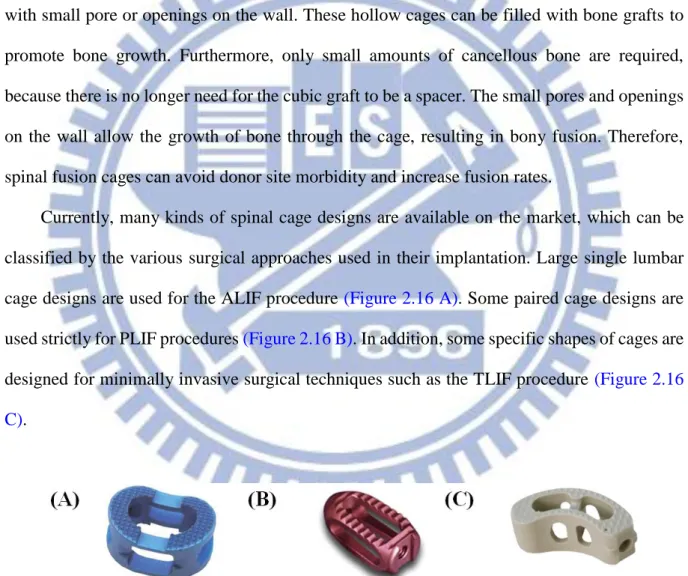
Currently, many kinds of spinal cage designs are available on the market, which can be
classified by the various surgical approaches used in their implantation. Large single lumbar
cage designs are used for the ALIF procedure (Figure 2.16 A). Some paired cage designs are
used strictly for PLIF procedures (Figure 2.16 B). In addition, some specific shapes of cages are
designed for minimally invasive surgical techniques such as the TLIF procedure (Figure 2.16
C).
Figure 2. 16: Various lumbar interbody fusion cages: (A) SynCage-Open (Synthes Spine, Inc.,
PA, USA); (B) O.I.C. (Stryker Spine, Mahwah, New Jersey, USA); (C) AVS-TL (Stryker Spine,
23
2.2.6. Minimally invasive techniques and stand-alone implant
Since 1991, when Obenchain described the first laparoscopic lumbar discectomy [3], the field of minimally invasive spine surgery has continued to evolve. Surgeon and patient alike
have been attracted by the advantages of minimally invasive surgery, including less tissue
trauma during the surgical approach, less postoperative pain, shorter hospital stays, and faster
return to activities of daily living.
The reported advantages of minimally invasive surgery led to the laparoscopic anterior
lumbar approach and mini-open ALIF becoming commonly performed procedures [71-80]. However, when examining the researches that have been performed to date, the results
showed that ALIF has provided less than desirable stability in unstable spinal segments [81]. Presently, it is common to clinically perform an additional posterior fixation to recover the
stability of spinal segments, as well as to enhance the fusion. The construct stability can be
further enhanced by the supplementation of posterior fixation such as pedicle or facet screws
[82, 83]. However, the significant morbidities of the combined anterior and posterior approaches have been mentioned [84]. Therefore, if sufficient stability can be provided in a single surgery, the problems that arise from extensive anterior and posterior approaches can
be reduced.
The stand-alone implants can be inserted via anterior or lateral approach with minimal
operative morbidity and without causing damage to posterior bony elements and neural,
vascular, and muscular tissues [85]. These stand-alone implants could reduce the postoperative pain and number of days of hospitalization, and could lead to a quick return to one’s daily routine.
Development of cages combining with integrated fixation may provide surgeons with
sufficient construct stability to allow stand-alone use, removing the need for additional
fixation. These stand-alone devices generally comprise a interbody cage with single or
24
adjacent inferior and superior vertebral bodies [85, 86] (Figure 2.17). The stand-alone implants have been used in ALIF treatment and their ability to stabilize the intervertebral
motion has been reported to be superior in flexion and bending compared to extension and
rotation[81, 87].
In the literatures [71, 72, 81], comparisons between different conventional stand-alone ALIF cages have been extensively conducted by the experimental, numerical, and clinical
methods. Using human cadavers as specimens, the three-dimensional stiffness tests in
Schleicher’s study [71] demonstrated the effective stabilization ability of the stand-alone SynFix cage in all physiological motion directions. In Chen's study [88], the numerical results showed no differences of ROM in extension and lateral bending between the SynCage-Open
and the stand-alone Stabilis cage. Except for the differences among cage frames, the stabilizing
mechanism might contribute to the postoperative outcome of the stand-alone ALIF[85]. Cho et al. [72] demonstrated that the stand-alone ALIF cage could assure good clinical results in the surgical treatment of symptomatic lumbar intervertebral foraminal stenosis in a mid-term
follow up. From the biomechanical viewpoint, however, the insertion depth and holding power
were quite different between the plate, screw, and cylinder, thus, potentially affecting the
stabilizing ability of the stabilizing mechanisms [89]. At present, there has been no extensive study devoted to investigate the kinematic and mechanical differences between the plate-,
screw-, and thread-type stand-alone cages.
The current study describes a novel, minimally disruptive spine device called the Latero
(Figure 2.17 A). This novel device can be used to gain access to the lumbar spine via a lateral
approach that passes through the retroperitoneal fat and psoas major muscle. Hence, the
potential complications with an anterior approach to the lumbar spine can be avoided, major
vessels are not encountered. In this study, two conventional stand-alone cages, consisting of
trapezoid frames that incorporates the stabilizing components were also investigated. The
25
implant (Figure 2.17 C) accommodates a threaded cylinder to anchor the superior and inferior
endplates. Simultaneously, SynCage-Opne (Figure 2.17 D) interbody cage supplementation
with posterior pedicle screw fixation was selected to represent the traditional fusion model in
this study.
Figure 2. 17: Front and left side views of the four ALIF cages were used in this study. (A)
26
Chapter 3 Materials and Methods
3.1 Part-1 of this study
Initial promise of a stand-alone interbody fusion cage to treat chronic back pain and
restore disc height has not been fully realized. In some instances, a posterior spinal fixation
has been used to enhance stability and increase fusion rate. In the part-1 of this study, a new
stand-alone cage is compared with two conventional stand-alone implants and one
conventional fixation method (ALIF plus pedicle screws: A+P) based on the finite element
analysis, with a focus on investigating cage-bone interface mechanics and stress distribution
on the adjacent tissues.
3.1.1. The establishment of intact lumbar spine model (INT model)
To create a three-dimensional FE model, computed tomography scan DICOM files of the
L1 to L5 lumbar spine of a middle-aged male were obtained at 1-mm intervals. The
commercially available visualization software Amira 3.1.1 (Mercury Computer Systems, Inc.,
Berlin, Germany) was used to describe cross-section contours of each spinal component in
accordance with gray scale value (Figure 3.1). Then, the three-dimensional surface geometries
were constructed through sequential processed cross-section contours as shown in Figure 3.2 A.
Each spinal component was exported as a Drawing Exchange Format (DXF) file and converted
to the Initial Graphics Exchange Specification (IGES) file as shown in Figure 3.2 B. The FE
analysis software ANSYS 14.0 (ANSYS Inc., Canonsburg, PA) was used to reconstruct the FE
model by converting the IGES file to ANSYS Parametric Design Language (APDL) code in
Figure 3.2 C. The INT model was an osseo-ligamentous lumbar spine, which included the
vertebrae, intervertebral discs, endplates, posterior bony elements, and all seven ligaments
27
Eight-node solid element (SOLID185) were used for modeling the cortical bone,
cancellous bone, posterior bony element, cartilage endplate, and annulus ground substance. The
cortical bone and cancellous bone were assumed to be homogeneous and transversely isotropic
[90]. The posterior bony element and cartilage endplate were assumed to be homogeneous and isotropic [90]. The intervertebral disc consisted of annulus ground substance, nucleus pulposus and collagen fibers embedded in the ground substance. The nonlinear annulus ground substance
was simulated by using a hyper-elastic Mooney-Rivlin formulation [91, 92]. The collagen fibers simply connected between nodes on adjacent endplates to create an irregular criss-cross
configuration. These irregular angles of collagen fibers were oriented within the range of the
Marchand’s study[93]. In the radial direction, twelve double cross-linked fiber layers were defined to decrease elastic strength proportionally from the outermost layer to the innermost.
Therefore, the collagen fibers in different annulus layers were weighted (elastic modulus at the
outermost layers 1-3: 1.0, layers 4-6: 0.9, layers 7-9: 0.75, and at the innermost layers 10-12:
0.65; cross sectional areas at the outermost layers 1-3: 1.0, layers 4-6: 0.78, layers 7-9: 0.62, and
at the innermost layers 10-12: 0.47) based on previous studies [94, 95]. The nucleus pulposus was modeled as an incompressible fluid with a bulk modulus of 1666.7 MPa by eight-node
fluid elements (FLUID80) [90]. 43 % of the cross-sectional area in the disc was defined as the nucleus, which was within the range of the study by Panagiotacopulos (30-50 %) [96]
Therefore, approximately 47 % to 49 % disc volume was assigned to nucleus pulposus. All
seven ligaments and collagen fibers were simulated by using two-node bilinear link elements
(LINK10) with uniaxial tension resistance only, which were arranged in an anatomically
correct direction [97]. The cross-sectional area of each ligament was obtained from previous studies [94, 98, 100], and material properties of the spine are listed in Table 3.1. The facet joint was treated as having sliding contact behavior using three-dimensional eight-node
surface-to-surface contact elements (CONTA174), which may slide between three-dimensional
28
between a pair of facet surfaces was kept within 0.5 mm [90]. The stiffness of the spinal structure changes depending on the contact status, so the standard contact option in ANSYS
was adopted to account for the changing-states nonlinear problem in this study. In addition, the
element’s shape will change after applying bending moments, thus changing the individual element stiffness. Therefore, the large displacement analysis option in ANSYS was chosen to
solve this geometric nonlinear problem. The INT model consisted of 112,174 elements and
94,162 nodes [102, 103].
Figure 3. 1: Each spinal component was selected from computed tomography scan DICOM file
29
Figure 3. 2: Modeling process of the L3 vertebra: (A) surface geometries of vertebra were
reconstructed through sequential processed computed tomography scan DICOM file; (B)
surface geometry was exported to the DXF file; (C) FE model of the L3 vertebra.
Figure 3. 3: The lumbar finite element model used in this study (Intact model from L1 to L5
30
Table 3. 1: Material properties used in the FE model
Material Element type Young’s modulus (MPa)
Poisson’s ratio Area (mm2) References Vertebral Cortical 8node-Solid 185 Ex=11300 Ey=11300 Ez=22000
xy=0.484
xz=0.203
yz=0.203 - [90] Gx=3800 Gy=5400 Gz=5400 Cancellous 8node-Solid 185 Ex=140 Ey=140 Ez=200
xy=0.45
xz=0.315
yz=0.315 - [90] Gx=48.3 Gy=48.3 Gz=48.3Posterior bony element 8node-Solid 185 3500 0.25 - [90] Disc
Nucleus pulposus Annulus Ground substance
8node-Fluid 80 8node-Solid 185 1666.7 C10=0.42 C01=0.105 - - - - [90] [98, 91] Annulus fibers 2node-Link 10 [94, 95]
Outmost (1-3 layers) 550 - 0.76 Second (4-6) 495 - 0.5928 Third (7-9) 412.5 - 0.4712 Innermost (10-12) 357.5 - 0.3572 Cartilaginous endplates 8node-Solid 185 24 0.4 - [90] Ligaments* ALL 2node-Link 10 7.8 - 24 [98,95,98] [100] PLL 10 - 14.4 TL 10 - 3.6 LF 15 - 40 ISL 10 - 26 SSL 8 - 23 CL 7.5 - 30
*ALL, anterior longitudinal ligament; PLL, posterior longitudinal ligament; TL, transverse
ligament; LF, ligamentum flavum; ISL, interspinous ligament; SSL, supraspinous ligament; CL,
capsular ligament.
3.1.1.1. Convergence test of INT model
In order to get reliable data, convergence test were conducted. Three mesh densities
31
finest model: 112,174 elements / 94,162 nodes) were selected to test ROM in the intact model
(Figure 3.4). The boundary and loading conditions of the test were that the inferior surface of
L5 vertebra was fixed, and 10 Nm moment and a 150 N pressure preload were applied to the
superior surface of L1 vertebra.
Compared with normal model and finest model, the variation of ROM was within 1.03%
in flexion (less than 0.2o), 4.39% in extension (less than 0.5o), 0.01% in axial rotation (less than 0.2o), and 0.001% in lateral bending (less than 0.1o). From the simulation results, the normal model only required fewer computational times to complete. However, several contact surfaces
in facet joint have stress concentration owed to the lower smooth geometry for fewer elements
and nodes. Therefore, the appropriate mesh density (finest model) was selected in this study.
Figure 3. 4: Convergence test of the intact model: (A) result of motion changes under flexion;
(B) result of motion changes under extension; (C) result of motion changes under axial rotation;
32
3.1.1.2. Follower load setting
During tasks of daily living the lumbar spine withstands compressive loads of very high
magnitude along with significant amounts of motion. Compressive loads can easily approach
several thousand Newtons during some lifting tasks [104]. Physiologic compressive loads applied to individual lumbar motion segments and the stiffening effect of compressive preload
on single functional spine units has been investigated [107]. For the in virtro test, difficulty arises in terms of stability of the lumbar spine when physiologic compressive loads are
applied to the entire lumbar spine. The traditional vertical preloads are unable to stabilize the
whole lumbar spine specimens under higher physiologic magnitude because the spine without
active musculature is unstable at around 100-200 N of vertical preload [108]. The follower load technique, described by Patwardhan et al. [14], applied compressive preload along a path following the lordotic curve of the lumbar spine, and allowed the in vitro spinal models to
support higher physiologic loads without damage or instability(Figure 3.5)[14, 109].
Figure 3. 5: (A)The illustration of applying follower load; The experiment setting of follower
load ((B) lateral view and(C) front view) [14].
Based on Patwardhan's [14] study, Rohlman [110] used ten fresh-frozen human cadaveric lumbar spines to determine the influence of different loading conditions on
33
intradiscal pressure and intersegmental rotation at all levels of the lumbar spine by applying
loads, including pure moments of 3.75, 7.5, and 7.5 Nm plus a follower load of 280 N (140 N
on each lateral side)(Figure 3.6). The 280 N corresponds to the partial body weight above the
L1 vertebra of a person weighing 66 kg. The results showed that a follower load in the range
of the partial body weight is sufficient to stabilize the spine.
Figure 3. 6: Lumbar spine specimen mounted in a spine tester and loaded with a pure moment
plus a follower load [110].
Because of the technical limitation of the current experimental set-up, a physiologic
compressive preload was applied only while assessing the kinematics in flexion and extension,
and was not applied in lateral bending or axial rotation. The preload resulting from muscle
activity has a stabilizing effect on a motion segment; therefore, the results pertaining to lateral
bending and axial rotation may be viewed as a worst-case scenario.
In finite element studies, the application of a great number of muscle forces is not a
problem, but still seldom used as the muscle forces are not known. The influence of muscle
34
element method. Patwardhan [14] support the following hypothesis concerning the action of muscles in the context of a frontal plane model: Muscle activation causes the internal force
resultant to follow a path approximating the tangent of the spinal curve, thereby minimizing the
internal shear forces and bending moments and loading the whole lumbar spine in nearly pure
compression.
Various numerical models have been used to show the follower load activation effectively
on the lumbar spine. Shirazi-Adl [111, 112] developed a method to apply physiologic compression to the lumbar spine through the use of posture changes and “wrapping” elements which wrap around prescribed spatial targets in the center of the endplates of each motion
segment such that the compressive load remains perpendicular to the mid-plane of each disc
(Fig 3.7). The caudal vertebra S1 is fixed while the remaining vertebrae L1-L5 are
unconstrained. Axially fixed compression loads of up to 2800 N are incrementally applied at
all L1-L5 vertebral centers (80% at the L1 and the rest evenly distributed among remaining
L2-L5 vertebrae to account for differential compression loads along the lumbar spine).
(A) (B)
Figure 3. 7: (A)The illustration of wrapping element; (B)the wrapping element applied on the
five levels lumbar spine [111,112].
35
model through a pair of two-node thermo-isotropic truss elements. The follower load trusses
were attached bilaterally to the cortical shell of the vertebrae of each motion segment such that
each truss spanned the disc, approximately passing through the instantaneous center of rotation
of each motion segment, optimizing the follower load path (Figure 3.8). Compressive load was
applied to each motion segment by inducing contraction in each of these truss elements by
decreasing the temperature in each truss. The results demonstrate that the ability of a large
follower load to stiffen the spine in all three planes. Because the follower load concept acts to
mimic optimized muscles forces, this study illustrates the important role of muscles in
providing spinal stability.
Figure 3. 8: Lateral view of Renner's[113] finite element model showing follower load trusses at each vertebra.
In Rohlmann's [114] study, the weight of the upper body acts in the center of gravity. Since flexion and extension occur in the sagittal plane, only four muscle groups were
simulated: left and right erector spinae, plus left and right rectus abdominis. A compressive
36
(Figure 3.9). The follower load was accomplished by forces of constant magnitude acting in the
centers of adjacent vertebral bodies (Figure 3.10).
Applying a follower load instead of a great number of small forces simulating the local
dorsal muscles makes realistic loading in in vitro studies feasible. It seems that for sagittal
plane motion few global muscle forces are sufficient to achieve realistic results. Rohlmann's
[114] results showed that the follower load is a suitable tool to adjust the intradiscal pressure to physiological values without significantly affecting intersegmental motion. However, the
local muscles act at a larger lever arm to the center of rotation than a follower load and thus
have a greater stabilizing effect. Therefore, local muscles contribute somewhat more to the
equilibrium of spinal moments than the follower load.
Figure 3. 9: Finite element model of the lumbar spine with the loads applied in Rolhman's
37
Figure 3. 10: The illustration of follower load of Rolhman's model [114].
In this study, two kinds of follower load setting for the finite element analysis were
proposed. In order to obtain a suitable setting for the follower load. The simpilied follower
load was applied on the center of the vertebra (Figure 3.11). In this setting, two hypotheses
are used. Firstly, a follower load was applied in the centers of vertebral bodies to substitute
for the unknown stabilizing effect of local muscles [114]. Secondly, the thermo-isotropic truss element is used to guarantee the resultant force always toward the center of the next vertebra
[113]. The second follower load setting is more close to the experimental set-up. The bilateral follower load was applied through the cable guides on the both side of the spine (Figure 3.12).
The two-node truss element is used to present the cable. The downward force was applied at
38
Figure 3. 11: The illustration of follower load (simplified: applied in the center).
Figure 3. 12: The illustration of follower load (bilateral: applied bilaterally)
In order to estimate both kinds of follower loads, a 10 Nm moments for four
physiological motions were applied. And there are four kinds of loading: 0 N (pure moment),
150 N (vertical load), 400 N (follower load: simplified) and 400 N (follower load: bilateral).
The results are shown in Figure 3.13. The results show that the simplified and the bilateral
follower load have similar performance in flexion, extension and rotation. But the bilateral
follower load setting shows significantly high stiffness in lateral bending. It is because of the
technical limitation of this set-up. Therefore, the results pertaining to lateral bending has the
39
of the Latero device is going to interfere with the guide device for the cable. Finally, since the
bilateral follower load setting is worse, the simipied follower load setting was used in further
study.
Figure 3. 13: Range of motion (ROM) calculated for the L1-L5 segments of intact lumbar
spine is compared to four kinds of preload condition.
3.1.1.3. Validation of INT model
For the validation of the INT model with follower load, the ROM of the intact model
under different loading moments was compared to Rohlmann’s[104] in vitro cadaveric study. Under 7.5 N-m moments without preload and with a 280 N follower load, the total ROM of
five segments lumbar were within one standard deviation in flexion-extension, axial rotation,
and lateral bending. The results are shown in Figure 3.14. The present model was verified for
40
Figure 3. 14: Range of motion (ROM) calculated for the L1-L5 segments of intact lumbar spine
is compared to previous in vitro experiments. (A)Intact lumbar spine without follower load;
(B)intact lumbar spine with simplified follower load.
3.1.2. The establishment of implant models
In order to establish the implant models, the geometric appearances of the implant
devices should be obtained. The implant devices were re-created by CAD software from the
real product and then transferred into the ANSYS software to construct the implant FE
41
Figure 3. 15: The implant devices used in this study. (A)Latero. (B) SynFix. (C)Stabilis.
(D)SynCage-Open
3.1.2.1. FE model of Latero implant (Latero model)
This model was a spine model implanted with the Latero device at the L3-L4 segment
(Figure 3.16). The Latero integrates a lateral vertebral plate into the trapezoid frame which is
bent to be parallel to the coronal plane. The geometry of the Latero device was re-created by
CAD software from the real product and then transferred into the ANSYS software to
construct the LateroFE model. The surface between the plate and the cage was modeled as
full bonding. The surface between the bones and the Latero device was modeled as a
surface-to-surface contact. The effect of teeth on the cage and the lateral plate of the Latero
device was simplified by assigning a higher coefficient of friction (0.8) to the contact area.
The higher coefficient of friction (0.8) was used in the contact interface to prevent device slip
motion [94]. The material used for the Latero device was Titanium alloy for the lateral plate and PEEK for the main cage. The Young’s modulus and Poisson’s ratio were listed on Table 3.2.
42
Figure 3. 16: The vertical view and lateral cross-sectional view of Latero implanted into
L3-L4 segment
3.1.2.2. FE models of conventional stand-alone ALIF implants (SynFix model and Stabilis model)
The SynFix and Stabilis devices were implanted at the L3-L4 segment for the
conventional stand-alone models (Figure 3.17). The SynFix system uses four screws to lock
the adjacent vertebrae (Figure 3.17 A). The Stabilis system accommodates a threaded cylinder
to anchor the superior and inferior endplates (Figure 3.17 B). The contact surfaces of the screw
with the bone and with the cage are set to be full bonding. The coefficient of friction of the
bone-cage interfaces was 0.8 to mimic a serrated surface for the initial stability of the trapezoid

![Figure 3. 10: The illustration of follower load of Rolhman's model [113]. ............................](https://thumb-ap.123doks.com/thumbv2/9libinfo/8509248.185730/13.892.123.819.296.907/figure-the-illustration-follower-load-rolhman-s-model.webp)
![Figure 2. 1: Vertebral column: Anterior, left lateral and posterior views of the major regions of the spine [15]](https://thumb-ap.123doks.com/thumbv2/9libinfo/8509248.185730/20.892.155.794.127.922/figure-vertebral-column-anterior-lateral-posterior-views-regions.webp)
![Figure 2. 2: The motion segment in the lumbar spine, which composed of two vertebrae and surrounding soft tissue [16]](https://thumb-ap.123doks.com/thumbv2/9libinfo/8509248.185730/21.892.132.806.130.913/figure-motion-segment-lumbar-composed-vertebrae-surrounding-tissue.webp)
![Figure 2. 4: In the intervertebral disc, the annulus fibrosus, made up of laminar layers of criss-crossed collagen fibers, surrounds the nucleus pulposus [16]](https://thumb-ap.123doks.com/thumbv2/9libinfo/8509248.185730/23.892.123.789.285.892/figure-intervertebral-annulus-fibrosus-laminar-collagen-surrounds-pulposus.webp)
![Figure 2. 8: The radiograph shows the spinal instability [34].](https://thumb-ap.123doks.com/thumbv2/9libinfo/8509248.185730/28.892.136.758.385.895/figure-radiograph-shows-spinal-instability.webp)
![Figure 2. 13: This radiograph demonstrates a solid bony union between L3 and L4 [61].](https://thumb-ap.123doks.com/thumbv2/9libinfo/8509248.185730/33.892.121.810.98.908/figure-radiograph-demonstrates-solid-bony-union-l-l.webp)
![Figure 2. 15: Interbody fusion combined with posterior pedicle screw fixation [65].](https://thumb-ap.123doks.com/thumbv2/9libinfo/8509248.185730/35.892.132.797.110.577/figure-interbody-fusion-combined-posterior-pedicle-screw-fixation.webp)