行政院國家科學委員會專題研究計畫 成果報告
數位典藏資訊之版權保護與驗證技術之研究(二)
計畫類別: 個別型計畫 計畫編號: NSC92-2422-H-009-010- 執行期間: 92 年 03 月 01 日至 93 年 02 月 28 日 執行單位: 國立交通大學資訊科學學系 計畫主持人: 蔡文祥 共同主持人: 吳大鈞 報告類型: 完整報告 處理方式: 本計畫可公開查詢中 華 民 國 93 年 5 月 18 日
行政院國家科學委員會補助專題研究計畫
成果報告
※※※※※※※※※※※※※※※※※※※※※※※※※※
※ ※
※
※
※ ※
※ ※
※ ※
※※※※※※※※※※※※※※※※※※※※※※※※※※
計畫類別:個別型計畫
計畫編號:NSC92-2422-H-009-010
執行期間:92 年 3 月 1 日至 93 年 2 月 29 日
計畫主持人:交通大學蔡文祥教授兼副校長
共同主持人:高雄第一科技大學吳大鈞副教授
執行單位:國立交通大學資訊科學系
數位典藏資訊之版權保護與驗證技術之研究(二)
A Study on Copyright Protection & Authentication
Techniques for Digital Information Archiving(2)
目錄
第一部份:成果報告成果略述………01 第二部分:計畫技術內容概述………03 一、視訊資料之資訊隱藏技術之開發………03 二、浮水印植入軟體之多家授權機制及技術之開發………04 三、影像及視訊多家授權機制及技術之開發………04 四、影像認證中心之運作………05 第三部份:已開發技術詳述………06Chapter 1—Data Hiding in MPEG Videos for Covert Communication………07
Chapter 2—Content Verification of MPEG Videos by Random Signal Hiding………33
Chapter 3—Multiple Authorizations for Images, Videos or Software Packages ………...…56
Chapter 4—Video Authentication for Copyright Claim………63
附件一:科學博物館所提建議之回覆..……….………...……66
附件二:交大與台中自然科學博物館會議記錄……….67
附件三:參加「第二屆數位典藏技術研討會」發表之論文— “Hiding Authenticable General Digital Information behind Binary Images with Reduced Distortion” ………69
第一部份 期末執行成果略述
本計畫「數位典藏資訊之版權保護與驗證技術之研究」執行時間為 92 年 3 月 1 日至 93 年 2 月 28 日,需完成之工作項目包括: 1. 視訊資料之資訊隱藏技術之開發﹔ 2. 浮水印植入軟體之多家授權機制及技術之開發﹔ 3. 影像及視訊多家授權機制及技術之開發; 4. 影像認證中心之運作。 針對上述四項技術,本計畫團隊經過一年積極的研究,已經完成視訊資料之資訊隱藏技 術之開發、浮水印植入軟體之多家授權機制及技術之開發、影像多家授權機制技術之開發、 視訊多家授權機制,以及影像認證中心之運作等成果。 此外,在去年 7 月 18 日,本計畫團隊與推廣辦公室合辦「數位典藏專業培訓課程系列四— 數位典藏版權資訊研討會」,邀集數位典藏單位以及相關學術單位共二十多個單位參加。除 了講解版權保護與驗證技術之發展歷程及現況之外,同時也發給參加人員「資訊保護家 2.0 版」應用軟體,讓各單位能在現場實際操作及發現問題。本計畫團隊也針對此次蒐集的問題 詳加研究並予以改進。 同時,本計畫也與台中自然科學博物館進行合作,除了去年與其數位典藏人員進行交流, 並聽取其意見,計畫團隊也針對其建議改善資訊保護家軟體,其意見與改善情形詳見附件一; 此外,去年計畫團隊在發展出初步研究成果之際,於 92 年 11 月 14 日前往自然科學博物館展 示軟體,並再次與其計畫人員交換意見、進行研討,本計畫綜合整理此次科博館對於目前軟 體所提供的意見(詳見附件二),同時針對科博館的意見,也提出解決的方法並持續修改軟 體,以期更加符合使用者的需求。 而在去年 7 月 22 日、23 日由數位典藏技術分項所舉辦的第二屆數位典藏技術研討會中, 本計畫發表了一篇論文─「Hiding Authenticable General Digital Information Behind Binary Images with Reduced Distortion」,其詳細內容如附件三。為了讓典藏單位能更了解浮水印的技術內涵,本計畫在今年 11 月 1 日出刊的《國家數位 典藏通訊》中,介紹本計畫所研發之軟體及相關技術。
此外依所研究的影像認證中心之運作,本計畫在一年前成立了交通大學影像認證中心, 而在本年度內,本中心設計了註冊證明書(詳見附件四),作為典藏單位到認證中心來註冊
對數位典藏單位有實質上的幫助。
值得一提的是本計畫團隊參加 2004 年數位典藏國家型科技計畫浮水印技術評比競賽獲 得「一般彩色影像組」與「大型彩色影像組」第一名。
第二部分:計畫技術內容概述
在技術部分,本計畫所需完成之工作項目有視訊資料之資訊隱藏技術之開發、浮水印植 入軟體之多家授權機制及技術之開發、影像及視訊多家授權機制及技術之開發、以及影像認 證中心之運作等四項,在這個部分將針對這些技術作概略的說明。 一、視訊資料之資訊隱藏技術之開發 視訊資料之資訊隱藏技術研發,主要進行下列兩項工作。 A. 以資料隱藏技巧植入註解資料於 MPEG 檔案中 由於視訊的傳輸必須要經過壓縮後才能達到快速傳輸的效果,因此,視訊的註解資訊 隱藏的技術首先要考慮到視訊的壓縮。目前有關於視訊隱藏的研究中,所能隱藏的機密資 訊限制在某幾類可以容忍失真的資訊形式上,如聲音、靜態與動態影像,因此本計畫的目 的之一便是研究視訊隱藏任意格式秘密資訊的可能性。一般來說,若要將一秘密資訊隱藏 在視訊中,可選擇在壓縮前、壓縮時以及壓縮後三種不同時機進行藏入動作。而資料取出 的方法,相對也有三種不同進行時機與之對應。本計畫團隊所採取的方式是在壓縮後將秘 密資訊藏入視訊檔案之中。 B. 以資料隱藏技巧植入認證資料於 MPEG 檔案中 由於認證浮水印較數位簽章的認證方式有更高的可攜性,因此,在本計畫中,我們採 用易碎浮水印的機制,研究的方法是根據人類視覺模式,將易碎浮水印以肉眼不可見的方 式植入視訊資料中。植入時並考慮幾何座標的位置,即在視訊某部分被修改的情況下,也 能夠影響所植入的浮水印,並根據浮水印的破壞情況,可以判別被竄改的部分。我們浮水 印認證方式的設計符合以下的需求: (1) 就一個畫面而言,我們將所隱藏之認證資訊必須平均分布於整個畫面中。因為畫 面中的每一個位置均有可能會被改變,一旦畫面內容被改變,所隱藏的認證資訊也跟著被 破壞。 (2) 當認證資訊隱藏到畫面中,會造成畫面的品質少部份的破壞或失真,所以我們所 使用的隱藏技術必須對畫質的影響不大。 (3) 認證資訊添加的過程所需要的時間愈少愈好。 如上所述,視訊資料量龐大,通常會以壓縮的方式以便儲存與傳輸。因此,在隱藏認 證浮水印時,也需要考慮到隱藏的時機。為了快速的添加浮水印,我們採取在壓縮後才進二、浮水印植入軟體之多家授權機制及技術之開發 本計畫團隊今年度發展出「資訊保護家 2.0 版」應用軟體,提供「數位典藏國家型科 科技計畫」之主題計畫將其 BMP、JPG 以及 GIF、TIFF 無壓縮等格式的靜態影像,以不同 的方法藏入多種版權資訊,以及進行自我驗證的動作。藉由「資訊保護家 2.0 版」,使用 者可針對上述四種數位影像格式,嵌入多種資訊以達到不同的功效。這些資訊分別為「註 解資訊」、「可視版權保護浮水印」、「不可視版權保護浮水印」,以及「驗證資訊」四 種。 先前使用的「資訊保護家 1.0 版」應用軟體採用不同的序號來管理,擁有此套軟體者, 能對其擁有影像執行藏入多種資訊及進行自我驗證的動作。而沒有此軟體者就無法一窺影 像中之奧秘。使用此軟體亦可對先前已藏入資訊之影像再藏入新資料,此時系統會覆蓋原 先藏入之舊資料。但倘若某個影像 A 已由「典藏機構甲」加入浮水印資訊而得影像 B,而 「典藏機構乙」若沒有先行驗證影像 B 中之浮水印資訊,仍可用其擁有的軟體對影像 B 執 行藏入新的浮水印的動作而得影像 C,新浮水印資訊會覆蓋掉原「典藏機構甲」所加入之 浮水印,也就是說影像 C 中無法得到「典藏機構甲」的浮水印。這時「典藏機構甲」與「典 藏機構乙」可能就會產生糾紛。當然,如果「典藏機構甲」曾經將影像在本認證中心註冊 則自然可以判定版權。 本計畫為避免此種因不小心而產生的典藏困擾與版權糾紛,發展出多家授權機制及技術, 並整合至「資訊保護家 2.0 版」。本計畫團隊所採行的做法是給每一典藏機構所擁有「資訊 保護家」應用軟體一個不同的設定值。當影像由某典藏機構之「資訊保護家」植入浮水印的 同時,也會自動植入該設定值。當任何影像要植入浮水印訊號時,系統會先自動查驗此影像 中是否已經存在不是該典藏機構的設定值,如果有的話則無法對此影像進行植入新資料之動 作。加入此機制後,因為只有使用原機構的「資訊保護家」才能對此己加入設定值的影像植 入新浮水印資訊,所以就不會發生前述糾紛。影像自我驗證及抽取資訊等動作則不檢查該設 定值,也就是說各典藏機構都可以利用其所擁有的「資訊保護家」查看其他典藏機構的影像 中之浮水印資訊。 三、影像及視訊多家授權機制及技術之開發 同一張影像(或視訊)若授權給多家機構運用,有可能發生其中某一授權機構侵權,卻 無法得知是哪一機構違法。舉例言之,某一機構可能將所獲授權影像(或視訊)再出售圖 利,但影像(或視訊)被發現時,卻無法得知是那一機構出售的,因為有多家機構皆擁有該 授權影像(或視訊)。因此我們藉由浮水印技術,在影像(或視訊)中藏入註解資訊來判定典 藏單位的授權機制,舉例來說,就是在註解資訊中藏入授權單位名稱、授權時間、授權內 容合約等,以此來達到影像(或視訊)多家授權的機制。 四、 影像認證中心之運作
在此我們希望建立一套視訊認證機制,用以保護數位資料的完整性及其版權。
。
我們所 提出的視訊的認證程序和認證中心是一個兩層的架構,最上層的稱為 Central AC,底層的稱 為 Local AC,下圖則是認證中心的架構圖。Central AC 是整個認證中心架構的最頂端,當底 下的 Local AC 發生爭議時就必須請求 Central AC 作公正的驗證工作。而 Local AC 則是一般 的片商、多媒體工作室或是電視台…等需要作視訊認證的地方。Local authentication center Local authentication center
Local authentication center
Local authentication center Central authentication center
Chapter 1
Data Hiding in MPEG Videos for Covert
Communication
1.1 Introduction
Due to the high availability of the Internet and the advance of multimedia techniques, there are many applications of digital data on the network. For example, images may be used for covert communication by data hiding techniques. However, the data hiding capacity of one image is usually not large. When the amount of secret data to be transmitted is huge, we have to use a lot of images for covert communication. A video usually consists of a long series of images, so we propose in this study a video data hiding method for the covert communication of large amounts of data. The proposed method is introduced in this chapter. In Section 1.1.1, some related problem definitions are given, and in Section 1.1.2 the basic ideas of the proposed method are presented. In Section 1.2, the proposed data hiding method is described, and the corresponding data extraction method is stated in Section 1.3. In Section 1.4, several experimental results are shown to prove the feasibility of the proposed method. Finally, some discussions and a summary of the proposed method are made in the last section of this chapter.
1.1.1 Problem Definition
When applying video data hiding techniques for covert communication, the data hiding capacity and the imperceptibility of the hidden data are two of the major concerns. In most existing methods, DCT coefficients in the frequency domain are used to hide data. However, not all types of frames of MPEG videos are suitable for data embedding in the DCT domain. At least, it is not easy
A solution for this problem is just to use the I frames of MPEG videos to hide data. However, most of the frames in an MPEG video sequence are inter-coded frames, instead of just I frames. To increase the data hiding capacity, embedding data in inter-coded frames is necessary. Aiming at this goal, an adaptive and efficient data hiding method utilizing both DCT coefficients and motion vectors of I, P, and B frames is developed in this study. The imperceptibility of the hidden data is also maintained by a method which selects proper frequency coefficients and motion vectors for data hiding.
1.1.2 Proposed Ideas
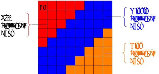
For I frames, it is proposed in this study to hide data into the middle frequency band of the DCT coefficients, which is one of the three frequency bands in an 8×8 DCT block defined in this study, as illustrated in Figure 1.1. On the other hand, the locations of the DCT coefficients used to hide data are selected dynamically in order to promote the security of the hidden data.
The idea of hiding data in P and B frames proposed in this study is to make a slight modification of the motion vectors in the frames. But not all motions vectors can be used to hide data. The reason will be explained in Section 1.2.2.
1.2 Hiding Secret data in MPEG Videos
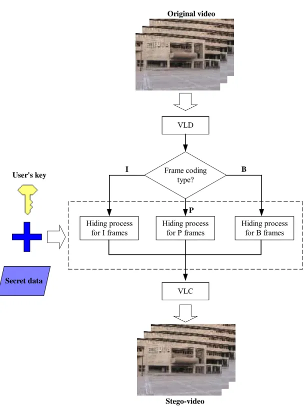
In this section, the proposed processes of hiding data into different types of frames of MPEG videos will be described. An illustration of the hiding method is shown in Figure 1.2. In Section 1.2.1, the process for hiding data in I frames will be described. The process for hiding data in P frames will be described in Section 1.2.2. Finally, the process for hiding data in B frames will be
Figure 1.1 Locations of the three frequency bands in a DCT block defined in this study. DC
Low
Frequency
Band
Middle
Frequency
Band
High
Frequency
Band
described in Section 1.2.3.
1.2.1 Process for Hiding Data in I Frames
Because I frames are coded without referencing to other frames, all macroblocks in an I frame are intra-coded. This coding fashion is similar to the compression technique of the JPEG standard. Therefore, a DCT-based method which is usually used for JPEG images is developed in this study to hide data into I frames.
Each 8×8 luminance block in an I frame can be used to hide four bits of data by making a slight modification of the DCT coefficients, and the imperceptivity of the hidden data can still be maintained because only coefficients at proper locations in the DCT domain are selected to hide data in the proposed method.
The selection of the coefficient locations in the DCT domain for data hiding will influence the degree of the imperceptibility of the hidden data, and so is an important task. In this study, the DCT coefficients with larger magnitudes are selected to hide data, because changing a larger DCT coefficient by decrementing or incrementing it by a small value will be less perceivable, compared with making the same decrement or increment in a smaller DCT coefficient. In addition, the user’s key will be hidden in the first I frame in order to ensure that the hidden data can be extracted only
Original video VLD Frame coding type? Hiding process for I frames Hiding process for P frames Hiding process for B frames I P B VLC Stego-video User's key Secret data
by a user who has the correct key.
The quantized DCT coefficients of each 8×8 block of a given I frame are taken as input to the data hiding process for I frames after performing variable length decoding on the input video. A detailed algorithm of the process is described in the following.
Algorithm 1: Hiding process for I frames.
Input: an I frame F in the quantized DCT domain, a user’s key R, and a secret data file D. Output: a stego-frame F’.
Steps:
1. With the aim of hiding 4-bit data in each 8×8 luminance block of F, compute data hiding capacity L as follows: , 8 4 4 ) ( R× C × × = mb mb L (1.1)
where mbR is the number of macroblocks in one row of F, and mbC is the number of
macroblocks in one column of F. And get L bytes from the secret data D.
2. Define four sections in the middle band in the DCT domain in a zigzag scanning order, as shown in Figure 3.3, and then find the DCT coefficient Ci whose magnitude is the maximum in each section.
0 1 5 6 14 15 27 28 2 4 7 13 16 26 29 42 3 8 12 17 25 30 41 43 9 11 18 24 31 40 44 53 10 19 23 32 39 45 52 54 20 22 33 38 46 51 55 60 21 34 37 47 50 56 59 61 Section 1 Section 2
3. Hide a bit d of D into each Ci according to the following two types of rules. (1) When Ci ≥ 0: + = = + = = unchanged. leave C otherwise C C set then odd is C and i D if C C set then even is C and i D if i i i i i i i , ; 1 , 0 ) ( ; 1 , 1 ) ( (1.2) (2) When Ci < 0: − = = − = = unchanged. leave C otherwise C C set then odd is C and i D if C C set then even is C and i D if i i i i i i i , ; 1 , 0 ) ( ; 1 , 1 ) ( (1.3)
I frame in the quantized DCT domain
Compute the data hiding capacity (L) of the input I frame
Find the coefficient whose magnitude is the maximun in each pre-defined section Ci is even? Ci is odd? Set Ci = Ci + 1 Set Ci = Ci + 1 Set Ci = Ci - 1 Set Ci = Ci - 1 Leave Ci unchanged Leave Ci unchanged No No No Yes Yes Yes No d = 1? Ci 0?≥ Ci 0?≥ No A bit d A selected coefficient Ci MB0MB1
A luminance block in each MB Each intra-coded MB L0 L1 L2 L3 Yes Yes Stego-frame MB0MB1 Secret data
Inter-coded frames are encoded by motion compensation prediction to reduce temporal redundancy. Therefore, hiding data in the motion vectors can utilize efficiently the information in the video bitstream to increase the data hiding capacity of the inter-coded frames. Moreover, there are still some intra-coded macroblocks which can be used to hide data in inter-coded frames.
In P frames, there are forward-coded and intra-coded macroblocks; therefore, two different hiding processes are proposed.
A. Hiding process for FMBs
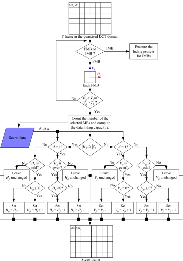
The motion vector of each forward-coded macroblock consists of a horizontal component and a vertical component. Each component will be used to hide data in the proposed method. However, not all of the forward-coded macroblocks are suitable for hiding data. First, only those macroblocks whose horizontal or vertical component magnitudes are large are selected. In other words, only those macroblocks which represent faster physical motions are utilized. This way, making a modification of the motion vector to hide data, will cause less perceivable degradation of the stego-video quality. Next, the magnitudes of the horizontal and vertical components of each selected forward-coded macroblock are compared with each other. The component whose magnitude is larger is selected to hide data, because changing a component whose magnitude is larger will be less perceivable, compared with changing another whose magnitude is smaller. A flowchart of the hiding process for forward-coded macroblocks is shown in Figure 1.5 and the corresponding detailed algorithm is described in the following.
Count the number of the selected MBs and compute
the data hiding capacity L A bit d Each FMB FMB or IMB ? Hfi Hfi > T1or V fi > T1 ? Leave Hfi unchanged fi fi V H ≥ Set Hfi = Hfi+ 1 d = 1? Hfi is even? Hfi 0?≥ Set Hfi = Hfi+ 1 Set Hfi = Hfi - 1 Leave Hfi unchanged Hfi 0?≥ Hfi is odd? d = 1? Leave Vfi unchanged Vfi is even? Vfi is odd? Vfi 0?≥ Vfi 0?≥ Set Vfi = Vfi + 1 Set Vfi = Vfi - 1 Set Hfi = Hfi - 1 Set Vfi = Vfi + 1 Set Vfi = Vfi - 1 Leave Vfi unchanged Vfi Yes Yes Yes Yes Yes Yes
Yes Yes Yes
Yes Yes No No Yes No No No No No No No No No No FMB Execute the hiding prosess for IMBs IMB Stego-frame MB0MB1
P frame in the quantized DCT domain
MB0MB1
Secret data
Output: a stego-frame F’. Steps:
1. For each forward-coded macroblock of the input P frame F, use the following rule to decide if the macroblock is proper to hide data:
, 1 1 or V T
T
Hfi > fi > (1.4)
where Hfi and Vfi are the horizontal component and the vertical one of the i-th forward-coded macroblock, respectively; and T1 is a pre-defined threshold value. And
then count the number N of selected proper macroblocks to compute a data hiding capacity L = N/8.
2. Hide a bit d of D into a corresponding selected motion vector according to the following four types of rules.
When |Hfi| ≥ |Vfi| and |Hfi| ≥ 0: + = = + = = unchanged. H leave otherwise, H H set then odd is H and d if H H set then even is H and d if fi fi fi fi fi fi fi ; 1 , 0 ; 1 , 1 (1.5) When |Hfi| ≥ |Vfi| and |Hfi| < 0: − = = − = = unchanged. H leave otherwise, H H set then odd is H and d if H H set then even is H and d if fi fi fi fi fi fi fi ; 1 , 0 ; 1 , 1 (1.6) When |Vfi| > |Hfi| and |Vfi| ≥ 0: + = = + = = unchanged. V leave otherwise, V V set then odd is V and d if V V set then even is V and d if fi fi fi fi fi fi fi ; 1 , 0 ; 1 , 1 (1.7) When |Vfi| > |Hfi| and |Vfi| < 0: − = = − = = unchanged. V leave otherwise, V V set then odd is V and d if V V set then even is V and d if fi fi fi fi fi fi fi ; 1 , 0 ; 1 , 1 (1.8)
Notice that the selection of the value of T1 is a tradeoff between the data hiding capacity and
video, however, at the expense of the resulting video quality. B. Hiding process for IMBs
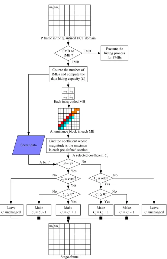
The hiding process for the intra-coded macroblocks of P frames is similar to the method used for I frames, except that now the number of the intra-coded macroblocks in an input P frame should be counted to compute the data hiding capacity before the data hiding work is started. A flowchart of the data hiding process for intra-coded macroblocks is shown in Figure 1.6 and a corresponding detailed algorithm is described in the following.
Algorithm 3: Data hiding process for the IMBs of P frames.
Input: a P frame F in the quantized DCT domain and a secret data file D.
Output: a stego-frame F’.
Steps:
1. Count the number N of the intra-coded macroblocks of the input P frame F, and compute the data hiding capacity L = (N×4×4)/8.
2. Define four sections in the middle band in the DCT domain in a zigzag scanning order, as shown in Figure 1.3, and find the DCT coefficient Ci whose magnitude is the maximum in each section.
3. Hide a bit d of D into the coefficient Ci according to the Equations (1.2) and (1.3).
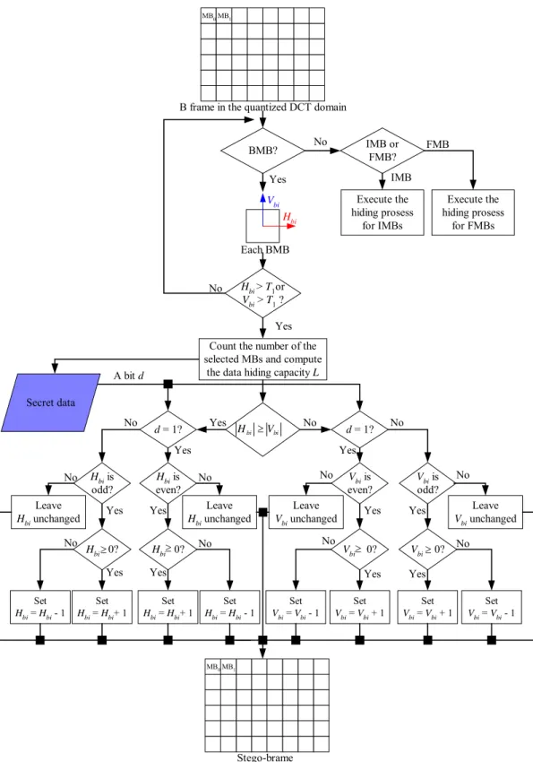
1.2.3 Process for Hiding Data in B Frames
The hiding process for the FMBs and IMBs of B frames are similar to that for P frames;
P frame in the quantized DCT domain
Counte the number of IMBs and compute the data hiding capacity (L)
Find the coefficient whose magnitude is the maximun in each pre-defined section
Ci is even? Ci is odd? Make Ci = Ci + 1 Make Ci = Ci + 1 Make Ci = Ci - 1 Make Ci = Ci - 1 Leave Ci unchanged Leave Ci unchanged No No No Yes Yes Yes No d = 1? Ci 0?≥ Ci 0?≥ No A bit d A selected coefficient Ci A luminance block in each MB
Each intra-coded MB L0 L1 L2 L3 Yes Yes FMB or IMB ? Execute the hiding process for FMBs FMB IMB MB0MB1 Stego-frame MB0MB1 Secret data
moreover, there is the new type of backward-coded macroblock (BMB) which can be used to hide data in B frames. A flowchart of the hiding process for backward-coded macroblocks is shown in Figure 1.7 and a corresponding detailed algorithm is described in the following.
Algorithm 4: Hiding process for the BMBs of B frames.
Input: a B frame F in the quantized DCT domain and a secret data file D.
Output: a stego-frame F’.
Steps:
1. For each forward-coded macroblock of the input B frame F, use the following rule to decide if the macroblock is proper to hide data:
, 2 2 or V T
T
Hbi > bi > (1.9)
where Hbi and Vbi are the horizontal and vertical components of the i-th forward-coded macroblock, respectively, and T2 is a pre-defined threshold value. And then count the
number N of the selected macroblocks to compute the data hiding capacity L = N/8. 2. Hide a bit d of D into the corresponding selected motion vector according to the
following four types of rules.
When |Hbi| ≥ |Vbi| and |Hbi| ≥ 0: + = = + = = unchanged. H leave otherwise, H H set then odd is H and d if H H set then even is H and d if bi bi bi bi bi bi bi ; 1 , 0 ; 1 , 1 (1.10)
When |Hbi| ≥ |Vbi| and |Hbi| < 0:
Count the number of the selected MBs and compute
the data hiding capacity L A bit d Each BMB BMB? Hbi Hbi > T1or Vbi > T1 ? Leave Hbi unchanged bi bi V H ≥ Set Hbi = Hbi+ 1 d = 1? Hbi is even? Hbi 0?≥ Set Hbi = Hbi+ 1 Set Hbi = Hbi - 1 Leave Hbi unchanged Hbi 0?≥ Hbi is odd? d = 1? Leave Vbi unchanged Vbi is even? Vbi is odd? Vbi 0?≥ Vbi 0?≥ Set Vbi = Vbi + 1 Set Vbi = Vbi - 1 Set Hbi = Hbi - 1 Set Vbi = Vbi + 1 Set Vbi = Vbi - 1 Leave Vbi unchanged Vbi Yes Yes Yes Yes Yes Yes
Yes Yes Yes
Yes Yes No No Yes No No No No No No No No No No Yes Execute the hiding prosess for IMBs No Stego-brame MB0MB1
B frame in the quantized DCT domain
MB0MB1 IMB or FMB? Execute the hiding prosess for FMBs IMB FMB Secret data
− = = − = = unchanged. H leave otherwise, H H set then odd is H and d if H H set then even is H and d if bi bi bi bi bi bi bi ; 1 , 0 ; 1 , 1 (1.11) When |Vbi| > |Hbi| and |Vbi| ≥ 0: + = = + = = unchanged. V leave otherwise, V V set then odd is V and d if V V set then even is V and d if bi bi bi bi bi bi fi ; 1 , 0 ; 1 , 1 (1.12) When |Vbi| > |Hbi| and |Vbi| < 0: − = = − = = unchanged. V leave otherwise, V V set then odd is V and d if V V set then even is V and d if bi bi bi bi bi bi bi ; 1 , 0 ; 1 , 1 (1.13)
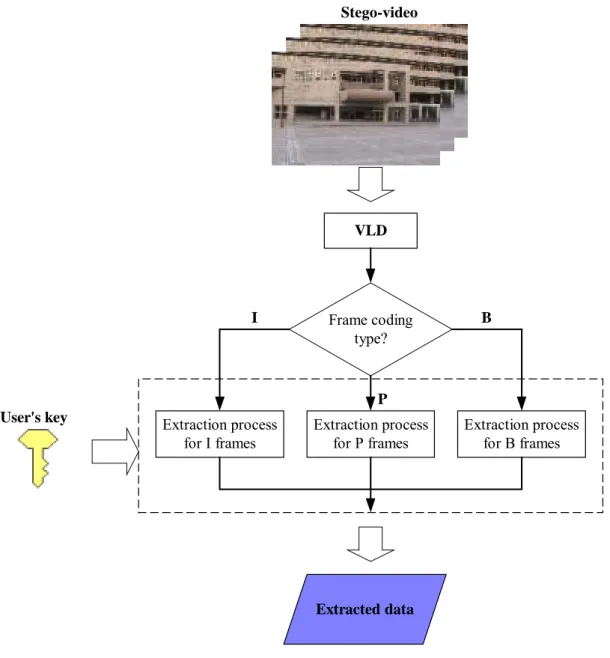
1.3 Extracting Secret Data from MPEG
Videos
In this section, the processes of extracting the hidden data from an input MPEG video will be described. An illustration of the proposed data extraction method is illustrated in Figure 1.8. In Section 1.3.1, the process for extracting data from an I frame will be described. Next, the process for extracting data from a P frame will be described in Section 1.3.2. Finally, the process for extracting data from a B frame will be described in Section 1.3.3.
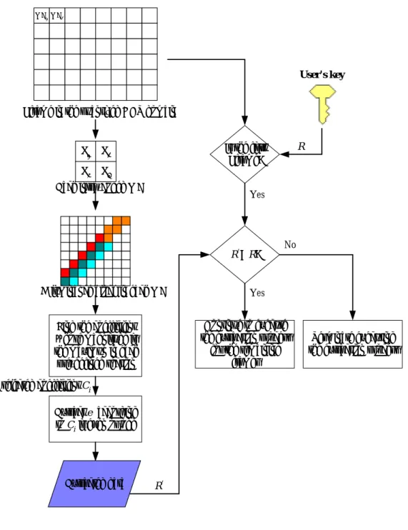
1.3.1 Process for Extracting Data from I Frames
The proposed data extraction process starts with the verification of the user’s key hidden in the first I frame. After performing variable length decoding on the input video, the quantized DCT coefficients of each 8×8 block of the I frame are retrieved and taken as input to the extraction process for I frames. A flowchart of the extraction process is shown in Figure 1.9 and a corresponding detailed algorithm is described in the following.
Stego-video VLD Frame coding type? Extraction process for I frames Extraction process for P frames Extraction process for B frames I P B User's key Extracted data
Algorithm 5: Extraction process for I frames.
Input: an I frame F in the quantized DCT domain and a user’s key R.
Output: an extracted data file E.
Steps:
1. For each 8×8 luminance block of the input frame F, find the DCT coefficient C whose
I frame in the quantized DCT domain
Find the coefficient whose magnitude is the maximun in each pre-defined section
Extract e according to Ci is even or odd A selected coefficient Ci
MB0MB1
A luminance block in each MB Each intra-coded MB L0 L1 L2 L3 Is the first I frame? R' = R? User's key Continue to execute the extraction process
for the remaining frames
Terminate executing the extraction process
R R' Yes Yes No Extracted data
= . otherwise , 0 odd; is if , 1 Ci e (1.14)
When F is the first frame of the input video, get the correct key R’ from the extraction result to verify the correctness of the input key R. If R is not identical to R’, the extraction process is terminated; otherwise, continue to execute the extraction process for the remaining frames.
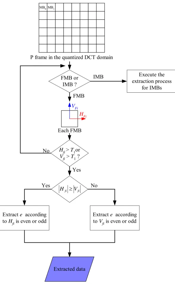
1.3.2 Process for Extracting Data from P Frames
A. Extraction process for FMBs
A flowchart of the extraction process for forward-coded macroblocks is shown in Figure 3.10 and a corresponding detailed algorithm is described in the following.
Algorithm 6: Extraction process for the FMBs of P frames.
Input: a P frame F in the quantized DCT domain.
Outputs: an extracted data file E.
Steps:
1. For each forward-coded macroblock of the input P frame F, use the following rule to check whether there are data hidden in it:
, 1 1 orV T
T
Hfi > fi >
where Hfi and Vfi are the horizontal and vertical components of the i-th forward-coded macroblock, respectively, and T1 is a pre-defined threshold value.
2. Extract a bit e as part of E from each corresponding motion vector according to the following two types of rules.
When |Hfi| ≥ |Vfi|: = . otherwise , 0 odd; is if , 1 Hfi e (1.15) When |Hfi| < |Vfi|: = . otherwise , 0 odd; is if , 1 Vfi e (1.16)
B. Extraction process for IMBs
A flowchart of the extraction process for the intra-coded macroblocks is shown in Figure 1.11 and a corresponding detailed algorithm is described in the following.
Algorithm 7: Extraction process for the IMBs of P frames.
Input: a P frame F in the quantized DCT domain.
Output: an extracted data file E.
Steps:
1. For each 8×8 luminance block of each intra-coded macroblock of the input P frame F, find the DCT coefficient Ci whose magnitude is the maximum in each pre-defined section to decide the locations used to hide data.
P frame in the quantized DCT domain Each FMB FMB or IMB ? HFi Hfi > T1or Vfi > T1 ? fi fi V H ≥ MB0MB1 VFi Yes No FMB Execute the extraction process for IMBs IMB Extract e according to Hfi is even or odd Extract e according to Vfi is even or odd Yes No Extracted data
P frame in the quantized DCT domain
Find the coefficient whose magnitude is the maximun in each
pre-defined section
Extract e according
to Ci is even or odd
A selectedd coefficient Ci
MB0MB1
A luminance block in each MB Each intra-coded MB L0 L1 L2 L3 FMB or IMB ? FMB Execute the extraction pocess for FMBs IMB Extracted data
A flowchart of the data extraction process for backward-coded macroblocks is shown in Figure 1.12 and a corresponding detailed algorithm is described in the following.
Algorithm 8: Extraction process for the BMBs of B frames.
Input: a B frame F in the quantized DCT domain.
Output: the extracted data file E.
Steps:
1. For the motion vector of each backward-coded macroblock, use the following rule to check whether the data are hidden in it.
, 2 2 or V T
T
Hbi > bi >
where Hbi and Vbi are the horizontal and vertical components of the i-th forward-coded macroblocks, respectively, and T1 is a pre-defined threshold value.
2. Extract a bit e as part of E from each corresponding motion vector according to the following two types of rules.
When |Hbi| ≥ |Vbi|: = . otherwise , 0 odd; is if , 1 Hbi e (1.17) When |Hbi| < |Vbi|: = . otherwise , 0 odd; is if , 1 Vbi e (1.18)
B frame in the quantized DCT domain Each BMB IMB ? HBi Hbi > T1or Vbi > T1 ? bi bi V H ≥ MB0MB1 VBi Yes No BMB Execute the extraction pocess for IMBs FMB Extract e according to Hbi is even or odd Extract e according to Vbi is even or odd FMB or BMB? Execute the extraction process for FMBs Yes No Yes No Extracted data
1.4 Experimental Results
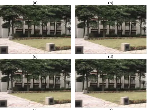
In our experiments, a video with frame size 352×240 was used as the input to hide a secret data file with the size of 2137 bytes. The data capacity of this video is 2554 bytes, so the secret data can be hidden into it completely. The secret data are shown in Figure 1.13, and six frames of the input video are shown in Figure 1.14. 655, 15, 31, 10, 31, and 30 bytes of data were hidden into the six frames, respectively. Six frames of the resulting stego-video are shown in Figure 1.15 and the PSNR values are shown in Table 1.1. The extracted data are shown in Figure 1.16. From Table 1.1, the PSNR values of the six frames are all acceptable. It shows that by applying the proposed method, the secret data can be hidden into MPEG videos imperceptibly.
In addition, the average data hiding capacity in a second is from 2KBs to 3KBs by our experimental experience. It has been found that the data hiding capacity is proportional to the amount of the motions coded in a video.
(a) (b)
(c) (d)
(e) (f) Figure 1.14 Six frames of the input video. (a) The first frame (I frame). (b) The
second frame (B frame). (c) The third frame (B frame). (d) The 4th frame (P frame). (e) The 5th frame (B frame). (f) The 6th frame (B frame).
Table 1.1 The PSNR values of the stego-video.
f0 (I) f1 (B) f2 (B) f3 (P) f4 (B) f5 (B)
PSNR 37.5 38.0 38.1 41.0 38.0 39.6
(c) (d)
(e) (f) Figure 1.15 Six frames of the stego-video. (a) The first frame (I frame). (b) The
second frame (B frame). (c) The third frame (B frame). (d) The 4th frame (P frame). (e) The 5th frame (B frame). (f) The 6th frame (B frame).
Chapter 2
Content Verification of MPEG Videos by
Random Signal Hiding
2.1 Introduction
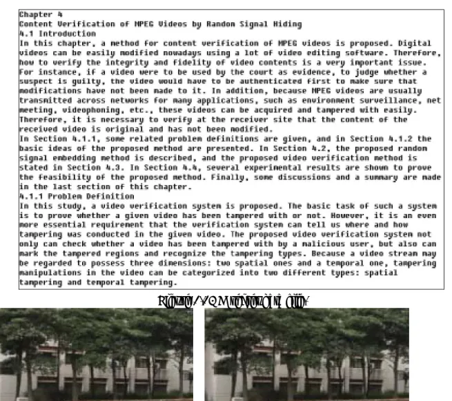
In this chapter, a method for content verification of MPEG videos is proposed. Digital videos can be easily modified nowadays using a lot of video editing software. Therefore, how to verify the integrity and fidelity of video contents is a very important issue. For instance, if a video were to be used by the court as evidence, to judge whether a suspect is guilty, the video would have to be authenticated first to make sure that modifications have not been made to it. In addition, because MPEG videos are usually transmitted across networks for many applications, such as environment surveillance, net meeting, videophoning, etc., these videos can be acquired and tampered with ease. Therefore, it is necessary to verify at the receiver site that the content of the received video is original and has not been modified.
In Section 2.1.1, some related problem definitions are given, and in Section 2.1.2 the basic ideas of the proposed method are presented. In Section 2.2, the proposed random signal embedding method is described, and the proposed video verification method is stated in Section 2.3. In Section 2.4, several experimental results are shown to prove the feasibility of the proposed method.
2.1.1 Problem Definition
tampering types.
Because a video stream may be regarded to possess three dimensions: two spatial ones and a temporal one, tampering manipulations in the video can be categorized into two different types:
spatial tampering and temporal tampering. Spatial tampering means any modification on the image
frame content, and temporal tampering means any manipulation performed on the image frame sequence.
In this study, temporal tampering of videos is categorized further into three types: cropping,
replacement, and insertion. Cropping means deletion of some video frames by a malicious user. An
illustration of frame cropping is shown in Figure 2.1. Insertion means addition of some fake video frames into the original video sequence. An illustration of frame insertion is shown in Figure 2.2. And Replacement means deletion of some video frames, followed by insertion of some other fake ones. An illustration of frame replacement is shown in Figure 2.3.
I 1 B 2 B 3 P 4 B 5 B 6 P 7 B 8 B 9
...
...
...
GOPi I 1 B 2 B 3 P 4 B 5 B 6 P 7 B 8 B 9 GOPj I 1 B 2 B 3 P 4 B 5 B 6 P 7 B 8 B 9 GOPj+1 I 1 B 2 B 3 P 4 B 5 B 6 P 7 B 8 B 9...
...
...
GOPi I 1 B 2 B 3 P 4 B 5 B 6 P 7 B 8 B 9 GOPj I 1 B 2 B 3 P 4 B 5 B 6 P 7 B 8 B 9 GOPj+1Figure 2.1 Illustration of cropping.
I 1 B 2 B 3 P 4 B 5 B 6 P 7 B 8 B 9
...
...
GOPi I 1 B 2 B 3 P 4 B 5 B 6 P 7 B 8 B 9 GOPi+1 I 1 B 2 B 3 P 4 B 5 B 6...
I 1 B 2 B 3...
P 7 B 8 B 9 P 7 B 8 B 9 I 1 B 2 B 3 P 4 B 5 B 6 P 7 B 8 B 9...
GOPi GOPi+1
Figure 2.2 Illustration of insertion. Original video
Tampering
Tampered video
Tampering
Fake video frames
Original video
2.1.2 Proposed Idea
To detect spatial tampering, some random signals, called authentication signals, generated according to a user’s key are embedded in each frame of the video. For I frames, authentication signals are embedded into the coefficients of the DCT domain. For P and B frames, authentication signals are embedded into the motion vectors in the frames.
From our analysis of temporal tampering, two features are proposed in this study for use in detecting temporal tampering in the proposed method. One is the index of the GOP of the video. The other is the number of the inter-coded frames in the GOP. Both features will be embedded into the I frames of a video for the purpose of tampering detection.
2.2 Embedding Random Signals in MPEG
Video
I 1 B 2 B 3 P 4 B 5 B 6 P 7 B 8 B 9...
...
...
GOPi I 1 B 2 B 3 P 4 B 5 B 6 P 7 B 8 B 9 GOPj I 1 B 2 B 3 P 4 B 5 B 6 P 7 B 8 B 9 GOPj+1 I 1 B 2 B 3 P 4 B 5...
...
GOPi B 6 P 7 B 8 B 9 GOPj I 1 B 2 B 3 P 4 B 5 B 6 P 7 B 8 B 9 GOPj+1 I 1 B 2 B 3 P 4 B 5 B 6 P 7...
...
Figure 2.3 Illustration of replacement. Tampering Original video
In this section, the proposed signal embedding method will be described. An illustration of the method is shown in Figure 2.4.
In Section 2.2.1, the process for embedding authentication signals in I frames will be described, followed by a description of the process for embedding authentication signals in P and B frames in Section 2.2.2.
2.2.1 Process for Embedding Random Signals in I Frames
In the proposed signal embedding process for I frames, two DCT coefficients, having the same quantization step size within the MPEG intra-quantization table of an 8×8 luminance block, are selected as a pair to embed an authentication signal. Embedding is made possible by adjusting the relative values of the coefficient pair. Since the quantization step size of the two selected DCT
Original video VLD Frame coding type? Embedding process for I frames I P B VLC Protected video User's key I 1 B 2 B 3 P 4 B 5 B 6 P 7 B 8 B 9 ... ... ... GOPi I 1 B 2 B 3 P 4 B 5 B 6 P 7 B 8 B 9 GOPj Embedding process for P frames Embedding process for B frames Index each GOP (Gi) and
count the number (Ni) of P
and B frames of each GOP
Gi & Ni
coefficients are equal, the relative sizes between them will not be affected even when the coefficients are re-quantized. That is, the embedded authentication signals are robust to survive moderate image recompression.
In this study, the index of the i-th GOP of the input video is denoted as Gi, and the number of the inter-coded frames of the (i-1)-th GOP is denoted as Ni. Gi and Ni are embedded into some pre-defined macroblocks of the i-th I frame in the same fashion as embedding authentication signals, as mentioned previously. In order to extract these two types of features precisely in the verification process, the proposed system duplicates them many times before embedding them to reduce the probability of misrepresentation.
The MPEG intra-quantization table is shown in Table 2.1. Let (x, y) denote the location of a coefficient in an 8×8 block. In this study, the coefficients located at (5, 1) and (6, 0) are selected as a pair to embed an authentication signal. Moreover, the coefficients located at (4, 5) and (5, 4) are selected as a pair to embed Gi and Ni.
Table 2.1 Standard intra-quantization table in the MPEG compression standard (luminance component). (x, y) 0 1 2 3 4 5 6 7 0 8 16 19 22 26 27 29 34 1 16 16 22 24 27 29 34 37 2 19 22 26 27 29 34 34 38 3 22 22 26 27 29 34 37 40 4 22 26 27 29 32 35 40 48 5 26 27 29 32 35 40 48 58 6 26 27 29 34 38 46 56 69 7 27 29 35 38 46 56 69 83
A flowchart of the proposed signal embedding process for I frames is shown in Figure 2.5 and a corresponding detailed algorithm is described in the following.
Algorithm 1: Signal embedding process for I frames.
K times to form a new binary string G’i.
2. Denote the binary form of Ni as Ni =n1n2…nL2, where L2 is the length of Ni. Duplicate Ni K times to form a new binary string N’
i.
3. For each 8×8 luminance block B, combine the input key R and the position P of B in F to form a seed for a random number generator to produce an authentication signal S.
4. Select the two DCT coefficient located at (5, 1) and (6, 0) in the intra-quantization table as a pair P1 = (C1, C2) to embed S. Before embedding S, compute diff1 = |C1 − C2|. Embed S
into P1 according to the following two types of rules.
When diff1 ≤ T3: = − > = − > . , ; , 3 2 1 1 2 3 2 1 2 1 T C C and C C set then even is S if T C C and C C set then odd is S if (2.1) When diff1 > T3: + = − = < − = + = < ); 2 / ( ) 2 / ( , ); 2 / ( ) 2 / ( , 3 1 2 3 1 1 1 2 3 1 2 3 1 1 2 1 T M C and T M C set then C C and even is S if T M C and T M C set then C C and odd is S if (2.2)
where M1 is the mean of C1 and C2 calculated as M1 = (C1 + C2)/2, and T3 is a pre-defined
threshold value.
5. If the block B is one of the pre-defined blocks selected to embed Gi or Ni, then select the two DCT coefficient located at (4, 5) and (5, 4) as a pair P2 = (C3, C4) to embed a bit b of
G’
i or N’i. Before embedding b, compute diff2 = |C3 – C4|. Embed b into P2 according to the following two types of rules.
When diff2 ≤ T3: = − > = = − > = . , 0 ; , 1 3 4 3 3 4 3 4 3 4 3 T C C and C C set then b if T C C and C C set then b if (2.3) When diff2 > T3: + = − = < = − = + = < = ); 2 / ( ) 2 / ( , 0 ); 2 / ( ) 2 / ( , 1 3 2 4 3 2 3 3 4 3 2 4 3 2 3 4 3 T M C and T M C set then C C and b if T M C and T M C set then C C and b if (2.4)
In the above algorithm, the threshold T mentioned in Step 4 is a tradeoff between the
I frame in the quantized DCT domain
Compute diff1 = |C1 - C2| A luminance block in each MB User's key I 1 B 2 B 3 P 4 B 5 B 6 P 7 B 8 B 9 ... ... ... GOPi I 1 B 2 B 3 P 4 B 5 B 6 P 7 B 8 B 9 GOPj
Index each GOP (Gi) and count the number (Ni) of P and B frames of each GOP
0 1 5 6 14 15 27 28 2 4 7 13 16 26 29 42 3 8 12 17 25 30 41 43 9 11 18 24 31 40 44 53 10 19 23 32 39 45 52 54 20 22 33 38 46 51 55 60 21 34 37 47 50 56 59 61 35 36 48 49 57 58 62 63 Random signal generation diff1 > T3 Set C1 > C2 and |C1 - C2| = T3 Set C2 > C1 and |C1 - C2| = T3 Set C1 = M1 + (T3/2) and C2 = M2- (T3/2) Compute M1 = (C1 - C2)/2 Set C1 = M1- (T3/2) and C2 = M2 +(T3/2)
Duplicate K copies and convert to the binary form
S is even? S is even? MB0MB1 No Yes Yes No Yes No P1 = (C1, C2) & P2 = (C3, C4) P R S Gi & Ni Protected frame MB0MB1
reduce the degradation of the resulting video quality caused by swapping C1 and C2 when the
difference between C1 and C2 is larger than T3.
2.2.2 Process for Embedding Random Signals in P and B
Frames
Since inter-coded frames are encoded by motion compensation prediction, embedding authentication signals in the motion vectors for authenticating the fidelity of inter-coded frames can utilize efficiently the information in the video bitstream. A detailed explanation has been stated previously.
In the proposed signal embedding process for each P or B frame of an input video, every two non-overlapping adjacent macroblocks in a P or B frame are selected to form a pair for embedding an authentication signal. However, not each pair is proper for embedding an authentication signal. The principles of selecting proper pairs are presented in the following.
For each pair of macroblocks (MBi, MBj) in a P frame, there are two candidates for embedding an authentication signal. One is (Hfi, Hfj); and the other is (Vfi, Vfj), where Hfi and Vfi are the horizontal and vertical components of the forward motion vector in the macroblock MBi, and Hfj and Vfj are the horizontal and vertical components of the forward motion vector in the macroblock
MBj. In this study, two principles of how to select a proper pair are proposed. First, motion vectors whose magnitudes are large should be selected. Secondly, the difference between the two components in a candidate pair must be small. The details of the proposed selection process are described in the following.
For each pair of macroblocks (MBi, MBj) in a B frame, there are four candidates: (Hfi, Hfj), (Vfi,
Vfj), (Hbi, Hbj), and (Vbi, Vbj), where Hbi and Vbi are the horizontal and vertical components of the backward motion vector in the macroblock MBi, and Hbj and Vbj are the horizontal and vertical components of the backward motion vector in the macroblock MBj.
A flowchart of the proposed signal embedding process for P and B frames is shown in Figure 2.6 and a corresponding detailed algorithm is described in the following.
P or B frame in the quantized DCT domain
Execute the selection process for
the input pair
User's key Random signal generation Set Hi > Hj and |Hi - Hj| = 1 S is even? S is even? MB0MB1 S R P1 P2 MBi Hi Vi MBj Hj Vj
Each pair of macroblocks
Select (Hi, Hj) or (Vi, Vj)? Set Hj > Hi and |Hi - Hj| = 1 Set Vi > Vj and |Vi - Vj| = 1 Set Vj > Vi and |Vi - Vj| = 1 Yes Yes No No (Hi, Hj) (Vi, Vj) Protected frame MB0MB1
The input pair is selected?
Yes
No
Output: a protected P or B frame F’.
Steps:
1. If the input frame F is a P frame, then perform Step 1.1; otherwise, perform Step 1.2. 1.1 For each pair (MBi, MBj) of non-overlapping adjacent macroblocks in F, select (Hfi,
Hfj) and (Vfi, Vfj) as two candidates for embedding an authentication signal where Hfi and Vfi are the horizontal and vertical components of the forward motion vector in
MBi, and Hfj and Vfj are the horizontal and vertical components of the forward motion vector in MBj. And use the following rule to judge whether (Hfi, Hfj) is proper to embed an authentication signal:
≤ − > > , 1 , , 4 4 fj fi fj fi H H T H T H (2.5)
where T4 is a pre-defined threshold value. If proper, then select (Hfi, Hfj) to embed an authentication signal; otherwise, use the following rule to judge whether (Vfi, Vfj) is proper to embed an authentication signal:
≤ − > > . 1 , , 4 4 fj fi fj fi V V T V T V (2.6)
If proper, then select (Vfi, Vfj) to embed an authentication signal. If the selected pair B consists of the horizontal components, then denote it as (Hi, Hj). On the contrary, if the selected pair consists of the vertical components, then denote it as (Vi, Vj).
1.2 For each pair (MBi, MBj) of non-overlapping adjacent macroblocks in the input B frame F, there are four candidates: (Hfi, Hfj), (Vfi, Vfj), (Hbi, Hbj), and (Vbi, Vbj), where
Hbi and Vbi are the horizontal and vertical components of the backward motion vector in MBi, and Hbj and Vbj are the horizontal and vertical components of the backward motion vector in MBj. The selection process for each pair of macroblocks (MBi, MBj) in a B frame is similar to the process used for P frames. Just use Equations (2.5) and (2.6), and (2.7) and (2.8) below sequentially to judge which candidate can be selected to embed an authentication signal:
≤ − > > . 1 , , 4 4 bj bi bj bi H H T H T H (2.7) ≤ − > > . 1 , , 4 4 bj bi bj bi V V T V T V (2.8)
If the selected pair B consists of the horizontal components, it is denoted as (Hi, Hj). On the contrary, if the selected pair consists of the vertical components, it is denoted as (Vi, Vj).
2. Combine the input key R and the position P of the selected pair B in F to form a seed for a random number generator to produce an authentication signal S.
3. If B is (Hi, Hj) from the first step, use the following rule to embed S:
= − > = − > . 1 , ; 1 , j i i j j i j i H H and H H set then even is S if H H and H H set then odd is S if (2.9)
On the contrary, if B is (Vi, Vj), use the following rule to embed S:
= − > = − > . 1 , ; 1 , j i i j j i j i V V and V V set then even is S if V V and V V set then odd is S if (2.10)
2.3 Content Verification
In this section, the proposed video content verification method will be described. An illustration of the method is shown in Figure 2.7. In Section 2.3.1, the process for verifying the integrity and fidelity of an I frame will be described. Next, the process for verifying the fidelity of a P or B frame will be described in Section 2.3.2.
embedded in each 8×8 luminance block of the I frame. This is useful for detecting spatial tampering. In addition, two pre-defined features can be extracted from each I frames to detect whether
temporal tampering has been attempted inside the input video. One feature is the index of each
GOP, denoted as G’
i; and the other is the number of the P and B frames in each GOP, denoted as
N’ i.
The content verification process for an I frame is divided into two steps. The first is to verify
Suspicious video VLD Frame coding type? Verification process for I frames I P B VLC Verified video User's key I 1 B 2 B 3 P 4 B 5 B 6 P 7 B 8 B 9 ... ... ... GOPi I 1 B 2 B 3 P 4 B 5 B 6 P 7 B 8 B 9 GOPj Verification process for P frames Verification process for B frames Count the number (Ni) of P
and B frames of each GOP
Ni
Verification report
each macroblock and extract G’
i and N’i. The second is to recognize the tampering types. A flowchart of the content verification process for I frames is shown in Figure 4.8 and a corresponding detailed algorithm is described in following.
I frame in the quantized DCT domain
A luminance block in each MB User's key 0 1 5 6 14 15 27 28 2 4 7 13 16 26 29 42 3 8 12 17 25 30 41 43 9 11 18 24 31 40 44 53 10 19 23 32 39 45 52 54 20 22 33 38 46 51 55 60 21 34 37 47 50 56 59 61 35 36 48 49 57 58 62 63 Random signal generation S is odd and C1 C2? S is even and C2 C1? MB0MB1 No Yes P1 = (C1, C2) P R Si ≤ ≤
Label the block as unauthentic
Verify whether each MB is suspicious
Use the relation of 4-neighbors to verify whether each MB is
unauthentic
Mark the unauthentic MBs as the tampered regions Extract G' i and N ' i by the voting scheme P2 = (C3, C4) Recognize the tampering type Verification report MB0MB1 The MB is unauthentic? Yes No
Input: the i-th I frame F and a user’s key R.
Output: the verified I frame and a verification report. Steps:
1. For each 8×8 luminance block B of the input I frame F, combine the input key R and the position P of B in F to form a seed for a random number generator to produce a random signal S.
2. Use the pre-defined pair P1 = (C1, C2) of the DCT coefficients to verify the existence of an
embedded authentication signal according to the following rule:
≤ ≤ . , ; , 1 2 2 1 c unauthenti as block this label then C C and even is S if c unauthenti as block this label then C C and odd is S if (2.11)
3. If the block B is one of the pre-defined blocks selected to embed the index G’i of each GOP, then use the pre-defined pair P2 = (C3, C4) of the DCT coefficients to extract a bit g’(j)
as part of the bitstream g’ according the following rule:
> = ; , 0 , 1 ) ( 3 4 ' otherwise ; C C if j g (2.12)
where 1 ≤ j ≤ L1×K, and L1 is the length of the binary form of G’i, and K is the number of copies used originally.
4. If the block B is one of the pre-defined blocks selected to embed the number N’
i of the P and B frames in each GOP, then use the pre-defined pair P2 = (C3, C4) of the DCT
coefficients to extract a bit n’(j) as part of the bitstream n’ according the following rule:
> = ; otherwise , 0 ; if , 1 ) ( C3 C4 j n' (2.13)
where 1 ≤ j ≤ L2×K, and L2 is the length of the binary form of N’i.
5. After processing each luminance block, employ the following three steps to verify each macroblock MB.
5.1 If two or more of the four luminance blocks of MB are considered unauthentic, then consider MB as suspicious.
5.2 If two or more of the 4-neighbors of a suspicious MB are considered suspicious, then consider MB as unauthentic. The 4-neighbor relationship is illustrated in Figure 2.9. 5.3 Mark unauthentic macroblocks as tampered regions.
, ) ( ) ( 1 0 1 '
∑
− = + × =K a m L a g m V (2.14)where 1 ≤ m ≤ L1. Then, reconstruct g(m) by the following rule:
> = , otherwise , 0 ; 2 ) ( if , 1 ) ( K m V m g (2.15)
where 1 ≤ m ≤ L1. And convertthe binary string g(m) into a decimal value G’i. 7. After extracting all bits of n’, perform majority voting to get a result as follows:
, ) ( ) ( 1 0 2 '
∑
− = + × =K a m L a n m V (2.16)where 1 ≤ m ≤ L2. Then reconstruct n(m) by the following rule:
> = , otherwise , 0 ; 2 ) ( if , 1 ) ( K m V m n (2.17)
where 1 ≤ m ≤ L2. And convertthe binary stringn(m) into a decimal value N’i.
8. If some macroblocks of F are considered unauthentic, decide that spatial tampering has been attempted inside the video. Then use the following rule to determine the temporal tampering type TTT: ≠ − = = − ≠ = − ≠ ≠ − = ≠ − − − − − ; , 0 ) ( 0 1 ) ( ; , 0 1 ) ( ; , 0 1 ) ( ; , 0 1 ) ( ' ' 1 ' ' 1 ' ' 1 ' ' 1 ' cropping is TTT then N N and E and G G if insertion is TTT then E and G G if t replacemen is TTT then E and G G if cropping is TTT then E and G G if i i i i i i i i i i i i i i (2.18) where G’
i and G’i-1 are the GOP indexes extracted from the i-th and (i-1)-th I frame, respectively; N’
i is the number of the P and B frames extracted from the i-th I frame; Ni is the number of the P and B frames in the (i-1)-th GOP of the input video; and Ei is the number of the unauthenticated frames before the i-th I frame.
2.3.2 Process for Verification of Fidelity of P and B Frames
In the content verification process of a P or B frame, a characteristic of inter-coded frames in the MPEG standard can be utilized to verify the fidelity of a frame, that is, the property that the number of the intra-coded macroblocks in P or B frames is usually small. If a P or B frame is manipulated illegally, then most of the macroblocks in the frame will become intra-coded ones, resulting in a great increase of the number of such macroblocks, because the illegal manipulation will cause the frame to become quite different from its reference frame. Therefore, the proportion of the number Nintra of the intra-coded macroblocks to the number Nall of the total macroblocks in the frame can be utilized for verifying the fidelity of the frame first. More specifically, if the proportion of Nintra to Nall is high, then this frame is decided to be unauthentic.
In the second verification step, the number Nsel of the pairs of macroblocks which satisfy the conditions specified by Equations (2.5) through (2.8) presented previously is checked. If Nsel is greater than a pre-selected threshold value, it means that the number of the authentication signals embedded in the frame is large enough, which may be used to verify the fidelity of the frame. On the contrary, if Nsel is smaller than a pre-selected threshold value, it indicates that the authentication signals embedded in the frame are insufficient for reliable fidelity verification. In this case, a method based upon a temporal reference relation is proposed in this study for verifying the frame. The method is presented as follows. For a P frame, if its forward reference frame is authentic, then the current frame is decided to be authentic; otherwise, the frame is decided to be unauthentic, and then the proposed verification system will mark as tampered those regions in the current frame whose corresponding regions in its forward reference frame were marked tampered.
For a B frame, the number Nf of the forward-coded macroblocks of the frame and the number
Nb of the backward-coded macroblocks of the frame must be compared first to decide whether the frame is similar to its forward reference frame or to its backward reference frame. If Nf is greater than Nb, it means the frame is similar to its forward reference frame. In this case, if its forward
Figure 2.9 Illustration of 4-neighbor relationship (The four green macroblocks are the 4-neighbors of the red one).