行政院國家科學委員會專題研究計畫 成果報告
無線區域網路提供區別服務之媒介存取控制機制研究與實
現(2/2)
計畫類別: 個別型計畫 計畫編號: NSC93-2213-E-009-046- 執行期間: 93 年 08 月 01 日至 94 年 07 月 31 日 執行單位: 國立交通大學電信工程學系(所) 計畫主持人: 李程輝 報告類型: 完整報告 處理方式: 本計畫可公開查詢中 華 民 國 94 年 8 月 11 日
Contents
Contents 1
List of Figures 3
List of Tables 4
Abstract 5
Part I: Dynamically Control Data Parameter for Protecting Real-Time Transmissions in IEEE 802.11e EDCA
6
I.1 Abstract………... 7
I.2 Introduction………... 7
I.3 A brief of IEEE 802.11e standard…..…... 8
I.4 Enhanced Distributed Channel Access………... 10
I.5 Proposed Algorithm………...……... 13
Part II: Data Rate Estimation Algorithm for the Scheduler of IEEE 802.11e Wireless LANs 18 II.1 Abstract………... 19
II.2 Introduction………... 19
II.3 HCF Controlled Channel Access………... 21
II.4 Proposed Algorithm………... 25
II.4.1 Data Rate Estimation and Prediction……..…... 26
II.4.3 Delay Analysis………... 30
Part III: Implementation of FPGA 33
III.1 Simulation………... 34
List of Figures
1 Diagram of IEEE 802.11e Architecture………... 9
2 DCF and EDCA Comparison……….………….………. 11
3 The Timing Diagram of EDCA.……….………. 12
4 The Control Mechanism at the t -th interval…..………. 17
5 CFP, CAP, and CP periods in IEEE 802.11e………... 22
6 Structure of service interval in referenced scheduler………... 24
7 Structure of the beacon interval……...…... 26
8 The diagram of data rate prediction…..………….……….. 27
List of Tables
1 Mapping of IEEE 802.1D User Priority to Access Category……….. 10
2 The Default EDCA Parameter Set………..…. 12
3 QoS requirements of different kind of traffic..……… 20
Abstract
With the fast deployment of wireless local area networks (WLANs), the ability of WLAN to support real time services with stringent quality of service requirements has come to the fore. HCF was designed to provide IP quality of service guarantees in IEEE 802.11e WLANs. Compared with the traditional best-effort transmission scheme, IEEE 802.11e presents architecture to do traffic differentiation according to different QoS requirements.
In the part I of the report, we will give a research on mechanisms for IEEE 802.11e EDCA. When the traffic load is getting heavier, the QoS of real-time traffic can not be assured. Thus, we proposed best-effort data control and admission control schemes that enable EDCA to provide quantitative bandwidth guarantees. Real-time transmissions and best-effort data transmissions are handled differently. The access point (AP) helps stations make decisions on acceptance or rejection of real-time traffic and dynamically control the data parameters to protect the existing real-time traffic according to the network condition.
In the part II of the report, from the evaluation of referenced scheduling scheme provided in IEEE 802.11e HCCA, we know that it does not perform well on traffic which is not strictly CBR. Therefore, we propose a more flexible scheme to dynamically adjust the estimation of TXOP allocated to the QSTA with different characteristics of applications. It is a data rate estimation algorithm for the scheduler of the IEEE 802.11e HCCA. With the proposed scheduling algorithm, the QAP can provide guaranteed quality of service parameters such as delay, packet loss rate, and throughput for the QoS-sensitive traffic.
Finally, in the part III, we evaluate our proposed algorithms on the ALTERA APEX 20KE Family BGA 652 PIN Emulation Board.
Part
I:
Dynamically Control Data Parameter for
Protecting Real-Time Transmissions in IEEE
I.1 Abstract
With the fast deployment of wireless local area networks (WLANs), the ability of WLAN to support real time services with stringent quality of service requirements has come to the fore. In the thesis, we evaluate the capability of QoS support in the IEEE 802.11e standard, which is the medium access control (MAC) enhancement for QoS support in IEEE 802.11 standard. We find that EDCA provides satisfactory service differentiation among its different access categories. However, in the case of heavy load traffic, the QoS of real-time traffic can not be assured. Thus, we proposed best-effort data control and admission control schemes that enable EDCA to provide quantitative bandwidth guarantees. Real-time transmissions and best-effort data transmissions are handled differently. The access point (AP) helps stations make decisions on acceptance or rejection of real-time traffic and dynamically control the data parameters to protect the existing real-time traffic according to the network condition.
I.2 Introduction
The past few years have seen an explosion in the deployment of wireless networks conforming to the IEEE 802.11 standard [1]. Consumers require more convenient and powerful wireless technology to facilitate the QoS of the online chatting or videoconference, etc. Therefore, the IEEE 802.11e group is developing MAC improvements to support QoS applications to make more efficient use of the wireless channel.
The original IEEE 802.11 MAC protocol included two modes of operation characterized by coordination functions: DCF and PCF. The IEEE 802.11e draft [2]
mainly concerns the MAC layer protocol, which introducing new EDCA and HCCA mechanisms. That means the modification is only in the MAC layer and it can provide different service quality for traffic streams with different priorities. Many works, [3], [4], [5] and [6], have been done. However, the main focus was on studying the EDCA differentiated mechanisms. Traffic belonging to a higher priority class has a higher probability of transmission, thus achieving a higher throughput when competing with lower priority traffic. But, no guarantee of higher priority traffic in terms of throughput and delay performance is given since the spirit of the IEEE 802.11e is also based on contention based access mechanisms.
In this thesis, we proposed an admission control scheme to protect existing real time traffic at high network loads. With this scheme, we can provide guaranteed throughput of real time traffic. With comparing with the HCCA mechanism, the scheme is easier to be implemented on QAP and QSTA. Then, simulation results demonstrate the practicable to protect the existing traffic and manage the resources effectively according the network condition.
I.3 A brief of IEEE 802.11e standard
No priority mechanism is involved in DCF. All the packets are treated using the first come first serve philosophy. When the number of stations increases, the probability of collision becomes higher and results in performance degradation. Although PCF can support some time-bounded traffic, many problems have not been clearly solved, such as unknown transmission duration of polled stations and hard to predict the amount of frames stations want to send.
To solve these problems, the medium access schemes of IEEE 802.11 are enhanced to the upcoming future standard IEEE 802.11e. In this draft, a new method,
Hybrid Coordination Function (HCF), is introduced to support QoS requirement. The architecture is described in Fig. 1. The HCF defines two medium access mechanisms: one is Enhanced Distributed Channel Access (EDCA) which is for the differential services requirement, and the other is HCF Controlled Channel Access (HCCA) which is used for the integrated services requirement. The EDCA manages the medium access in the CP while the HCF is responsible for the CFP and the CP.
Distributed Coordination Function, DCF Point Coordination Function (PCF) MAC Extent
Used for Contention Services and basis for PCF and HCF HCF Contention Access (EDCA) HCF Controlled Access (HCCA) HCF
Fig.1 Diagram of IEEE 802.11e Architecture
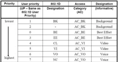
For achieving QoS, HCF introduce four access category (AC) queues and eight traffic stream (TS) queues. When a packet arrives at the MAC layer, it is tagged with a traffic priority identifier (TID) according to its QoS requirement. The packets with TID values from 0 to 7 are mapped into four AC queues and those with TID values from 8 to 15 are mapped into eight TS queues which are specified in IEEE 802.1D, as in Table 1. The reason of separating TS queues from AC queues is to provide strict QoS at TS queues. Transmission opportunity (TXOP) is another feature of the HCF. TXOP is the time interval which is permitted for a certain station, getting the control of the medium, to transmit packets. During the TXOP, a station can transmit a series of packets separated by SIFS. If the frame exchange sequence has been completed, and there is still time remaining in the TXOP, the station can may extend the frame exchange sequence by transmitting another frame in the same access category. The station must ensure that the transmitted frame and any necessary acknowledgement can fit into the time remaining in the TXOP.
Table 1 Mapping of IEEE 802.1D User Priority to Access Category
I.4 Enhanced Distributed Channel Access
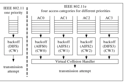
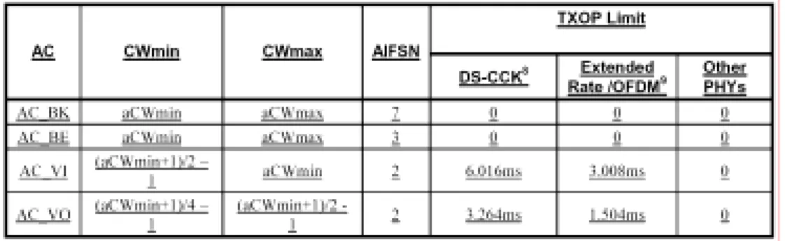
Instead of using a single queue and one channel access function as in DCF, each station implements multiples ACs, as shown in Fig. 2. Each AC queue works as an independent DCF station and uses its own backoff parameters, that include minimum and maximum Contention Windows (CWmin, CWmax), Arbitration InterFrame Space (AIFS) and TXOP duration. These parameters are defining EDCA operation are store locally at the stations. These ones will be different for each access category (queue) and can be dynamically updated by the QoS access point (QAP) for each access category through the EDCA parameter sets. These are sent from the QAP as part of the beacon, and in probe and reassociation response frames. This adjustment allows the stations in the network to adjust to changing conditions, and gives the QAP the ability to manage overall QoS performance. Different IFS and CW sizes for different ACs are introduced to support service differentiation. Operation of each channel access function is similar to DCF. Data transmission begins when the medium is idle longer than the AIFS time, with AIFS ≥DIFS. The AIFS[AC] is determined by equation (I.1) and the default values of the Arbitration InterFrame Space Number
(AIFSN) is defined in Table 2.
AIFS
[ ]
AC = AIFSN[ ]
AC ⋅slot_time+SIFS (I.1)backoff (DIFS) (CW) transmission attempt IEEE 802.11 one priority backoff (AIFS0) (CW0) AC0 backoff (AIFS1) (CW1) AC1 backoff (AIFS2) (CW2) backoff (DIFS3) (CW3) AC2 AC3
Virtual Collision Handler transmission attempt
IEEE 802.11e
four access categories for different priorities
Fig. 2 DCF and EDCA Comparison
As shown in Table 2, different CW sizes are allocated to different AC queues. Assigning a short CW size to a high priority AC ensures high-priority AC is able to transmit frames ahead of low-priority AC. If the backoff counter of two or more parallel ACs in a single station expires simultaneously, a scheduler inside the station treats the event as a virtual collision without recording a retransmission. Then, the TXOP is given to the high-priority AC and the other colliding ACs will enter a backoff process as if a collision on the medium occurred. AIFS is the extra time slots, appended at the beginning of each backoff contention window, which means the backoff random number is between AIFS and AIFS+CW, as shown in Fig. 3. Therefore, different ACs have different length of AIFS, thus reducing the probability of low-priority AC to be transmitted.
Table 2 The Default EDCA Parameter Set
Fig. 3 the Timing Diagram of EDCA
Contention-based medium access is susceptible to severe performance degradation when overloaded. In overload conditions, the contention windows become large, and more and more time is spent in backoff delays rather than sending data. Admission control regulates the amount of data contending for the medium. EDCA admission control is mandatory at the AP, and optional at the station. The QAP may indicate that it requires stations to support admission control and explicitly request access rights by using the admission control mandatory (ACM) flags if they wish to use an access category. Admission control is negotiated by the use of a traffic specification (TSPEC). A station specifies its traffic flow requirements (data rate, delay bounds, packet size, and others) and requests the QAP to create a TSPEC by sending the ADDTS (add TSPEC) management action frame. The QAP calculates the existing load based on the current set of issued TSPECs. Based on the current
conditions, the QAP may accept or deny the new TSPEC request. If the TSPEC is denied, the high priority access category inside the QoS station (QSTA) is not permitted to use the high priority access parameters, but it must use lower priority parameters instead. Admission control is not intended to be used for the best effort and background traffic classes, which classified as AC_BE and AC_BK respectively.
I.5 Proposed Algorithm
In the EDCA mechanism, support of QoS can be easily achieved by reducing the probability of medium access for lower priority access categories. However, at high loadings of traffic, there are a large number of collisions even for high priority access categories so that the EDCA can not ensure achieving the QoS requirements since the EDCA is based on the CSMA/CA mechanism. Without a good admission control mechanism, the existing traffic can not meet the QoS requirements. In IEEE 802.11e, HCCA also provide guarantee QoS, but the mechanism is complex. In previous works, DCF is easier to achieve service differentiations than PCF, so it is the motivation to study the admission control mechanism based on the EDCA of IEEE 802.11e. In [7], [8], [9] and [10], the authors proposed some schemes to protect the existing real time traffic. We extend some of the authors’ ideas and propose new methods that provide procedures at the QAP and QSTAs for the contention-based admission control mechanism. All the procedures do not violate the guideline of the IEEE 802.11e draft and are able to greatly improve quality of services. In the proposed methods discussed below, the real-time traffic, such as video and voice traffic, and the best-effort data traffic are handled separately.
determination as to whether to accept or deny the request according the algorithm implemented in it. The QAP maintains variables TXOPBudget
[ ]
i , SurplusFactor[ ]
iand TxTime[i] for AC i , which i=1 for audio traffic, i=2 for video traffic, and 3i= for best-effort data traffic, respectively. TXOPBudget
[ ]
i is defined as the additional amount of time available for AC i during the next statistic period, hereusing the Beacon interval, Target Beacon Transmission Time (TBTT), as the period. ]
[i
TxTime is used to record the time of the frame transmission and all overhead involved such as SIFS and ACK frame corresponding to the AC of that frame.
[ ]
i torSurplusFac is used for calculating the unpredictable time, such as collisions or
retransmissions. So, the TXOPBudget
[ ]
i is determined by equation (I.2), where ][i
ATL is for the maximum amount of time that may be used for transmissions of AC
i per beacon interval.
TXOPBudget[i]=max
(
ATL[i]−TxTime[i]×SurplusFactor[i],0)
(I.2) Each QSTA has to maintain the following local variables for AC i : ]TxUsed[i ,] [i
TxSuccess , ]TxLimit[i , ]TxRemainder[i , and TxMemory[i]. ]TxUsed[i counts the amount of time occupied by transmissions. TxSuccess[i] counts for the successful transmission time. TxRemainder[i] is defined as equation (I.3).
] [i
TxLimit limits the maximum time that a QSTA could be used to transmit. A QSTA shall not transmit a frame if the time of TxRemainder[i] is not enough to transmit.
] [i
TxMemory memorizes the amount of time that a QSTA transmit frames of priority
i . All these variables update at each TBTT, and will be exploited in next TBTT.
TxRemainder[i]=TxLimit[i]−TxUsed[i] (I.3) So, if the TXOPBudget[i] becomes zero, new QSTAs can not start transmission with AC i and the other QSTAs’ TxMemory[i] remains unchanged. In other words,
when the transmission budget for an AC i is depleted, new QSTA can not transmit
frames of priority i , while the exiting traffic of priority i can not increase the
admitted time. At this moment, new QSTA which want to transmit AC i traffic
should change the parameters to lower priority class according to the IEEE 802.11e standard. If the TXOPBudget[i] is larger than zero, meaning that there is still enough resource, new traffic of priority i is allowed to transmit and its TxMemory[i] is a random time between 0 and TXOPBudget[i] SurplusFactor[i]. The other QSTAs’
] [i
TxMemory is a weighted average of the old TxMemory[i] and the sum of ]
[i
TxSuccess and TXOPBudget[i], as equation (I.4), where f is the damping
factor to effect the weighted value.
(
1) (
[] [ ] [])
] [ ] [ i TXOPBudget i tor SurplusFac i TxSuccess f i TxMemory f i TxMemory + × × − + × = (I.4)As time goes, TXOPBudget[i] fluctuates around 0 and TxMemory[i] converges to the value TxSuccess[i]×SurplusFactor[i], which is the lower limit for each QSTA. The meaning of equation (I.4) is that an existing traffic of a QSTA can continuously consume the same amount of time in subsequent TBTT. The procedure is used for the video and voice traffic, so the existing real-time traffic is protected from the new and other existing real-time traffic and then the QoS requirements could also be achieved under high loads.
Since the best-effort data transmissions, which is classified AC 0 , do not need guaranteed QoS, the QAP dynamically control the parameters for QSTAs based on the traffic condition. These parameters are CWmin[0], ]CWmax[0 , and AIFS[0] which will effect the throughput of data transmissions. The reasons of dynamically controlling the parameters are described as follows. Too many data transmissions may degrade the performance of the existing video or voice traffic. In this case, data
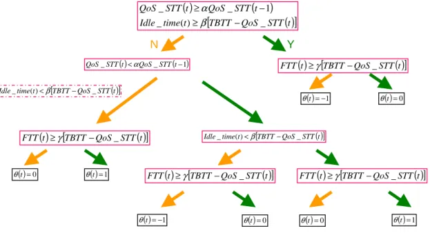
throughput should be decreased. On the other hand, if the channel condition becomes better and the performance of the video or voice traffic does not degrade a lot, we shall increase the data throughput as possible. However, the decision of increasing or decreasing the data throughput should be made according additional conditions, like if the successful transmission time of real-time traffic is increasing or not, in order not to cause a great damage to time-bounded traffic due to an aggressive approach to these parameters. The variables used for QAP to understand the channel condition are
STT
QoS _ , Data _STT, FTT , and Idle _Time, where QoS _STT is the sum of the successful transmission time of all real-time traffic, Data _STT is the successful transmission time of best-effort data, FTT is the total failure transmission time of all kinds of traffic, and Idle _Time is the time measured by QAP when the medium is idle. Based on judgments of an increased/decreased value of QoS _STT , FTT or
Time
Idle _ , we propose an algorithm of controlling the data parameters to maximize the data throughput under the condition of protecting the existing real-time traffic. The control mechanism is shown in Fig. 4.
α
and β denote a predefined successful ratio and a predefined failure ratio, respectively. First, we check if the throughput of the existing real-time traffic increases or decreases. Second, at high loads, the channel is idle usually due to the same backoff slots between QSTAs after each unsuccessful attempt. At this case, if Idle _Time is larger than Threshold , we prefer to shorten the contention window size; otherwise, we enlarge the contention window size. However, the increase of Idle _Time might be the cause of the existing traffic leaving. FTT is the third criterion of judgments on the case of suddenly leaving. In Fig. 4, all eight conditions are considered.θ
( )
t =1 denotes an increase of parameters for data at time t and means the decreasing of the data traffic load.θ
( )
t =−1 denotes a decrease of parameters for data at time t and means the increasing of the data traffic load.θ
( )
t =0 represents remaining unchanged. In oursimulation, we adopt the linear increasing/decreasing of these parameters, i.e. 1
min
min[0]=CW [0]±∆
CW , CWmax[0]=CWmax[0]±∆2, and AIFS[0]= AIFS[0]±∆3.
Fig. 4 The Control Mechanism at the t -th interval
( ) ( ) ( )
[
TBTT QoS STT t]
t time Idle t STT QoS t STT QoS _ ) ( _ 1 _ _ − ≥ − ≥ β α ( )t =−1 θ ( ) _ ( )1 _STTt < QoS STTt− QoS α ( ) [TBTT QoS STTt] t time Idle_ ()<β − _ ( )t =0 θ FTT( )t ≥γ[TBTT−QoS_STT( )t] ( ) [TBTT QoS STTt] t time Idle_ ()<β − _ ( )t =−1 θ θ( )t =1 ( )t [TBTT QoS STT( )t] FTT ≥γ − _ ( )t =1 θ FTT( )t ≥γ[TBTT−QoS_STT( )t] ( )t [TBTT QoS STT( )t] FTT ≥γ − _ N Y ( )t =0 θ ( )t =0 θ ( )t =0 θPart
II:
Data Rate Estimation Algorithm for the Scheduler
of IEEE 802.11e Wireless LANs
II.1 Abstract
As the real-time applications used in today’s wireless network grow, we need some schemes to provide more suitable service for them. HCF was designed to provide IP quality of service guarantees in IEEE 802.11e WLANs. Compared with the traditional best-effort transmission scheme, IEEE 802.11e presents architecture to do traffic differentiation according to different QoS requirements. This report presents a data rate estimation algorithm for the scheduler of the IEEE 802.11e Hybrid Coordination Function (HCF) Controlled Channel Access (HCCA) mechanism.
From the evaluation of referenced scheduling scheme provided in IEEE 802.11e, we know that it does not perform well on traffic which is not strictly CBR. Therefore, we need to design a more flexible scheme to dynamically adjust the estimation of TXOP allocated to the QSTA with different characteristics of applications. With the proposed scheduling algorithm, the QAP can provide guaranteed quality of service parameters such as delay, packet loss rate, and throughput for the QoS-sensitive traffic.
II.2 Introduction
In recent years, wireless networks such as the IEEE 802.11 WLANs are deployed widely and rapidly in many environments around us. We can enjoy the freedom and convenience of connecting to the internet with portable computing devices on the campus, at home, or in coffee shops. Today, 802.11 WLAN (referred to as legacy 802.11 in this article) can be interpreted as a wireless version of Ethernet that supports best effort service.
keeps increasing, the interest in wireless network that supports quality of service (QoS) has grown. There are already available mechanisms in the legacy 802.11 which are designed to support QoS, but because of their limitations they have not been implemented in real hardware. Therefore, the 802.11 working group initiated a new group “E” to define new MAC protocols in order to enhance the ability of supporting the applications that requires QoS.
From the data revealed in [11], we get the typical QoS requirements of various kind of traffic for several service classes: non-real-time variable bit rate (nrt-VBR), available bit rate (ABR), unspecified bit rate (UBR), constant bit rate (CBR) and real-time VBR (rt-VBR). Notice that the delay is measured between the QAP and QSTAs:
Class Application Bandwidth (b/s) Delay bound (ms) Loss rate
CBR Voice 32 k-2 M 30-60 10−2
nrt-VBR Digital video 1 M-10 M Large 6 10−
rt-VBR Videoconference 128 k-6 M 40-90 3 10−
UBR File transfer 1 M-10 M Large 10−8
ABR Web browsing 1 M-10 M Large 8 10− Table 3 QoS requirements of different kind of traffic [11]
The 802.11e introduces the hybrid coordination function (HCF) and defines two channel access mechanisms. The first one is a contention-based channel access referred to as enhanced distributed channel access (EDCA). The other is a controlled channel access referred to as HCF controlled channel access (HCCA). The controlled channel access is a polling-based scheme enhanced from point coordination function
(PCF) of legacy 802.11. The HCCA mechanism uses a QoS-aware centralized coordinator, called hybrid coordinator (HC), and operates under rules that are different from the point coordinator (PC) of the PCF.
Since real time traffic has stricter delay constrain than non-real-time traffic, it can only wait for a very short time before it is transmitted. Therefore, it needs higher priority and enough time to access the medium. In the draft of IEEE 802.11e, the HC can negotiate with the QSTAs that have real time traffic to send using the TSPEC field in ADDTS frame. The parameters HC obtains in its scheduler are mean values of the traffic specifications. But the inter-arrival time, data rate, and packet size may be variable for some application such as video conference. Therefore, if HC always estimates the possible traffics that need to be cleared off in service period by the TSPEC parameters, it may cause the delay and loss rate of VBR traffic to increase.
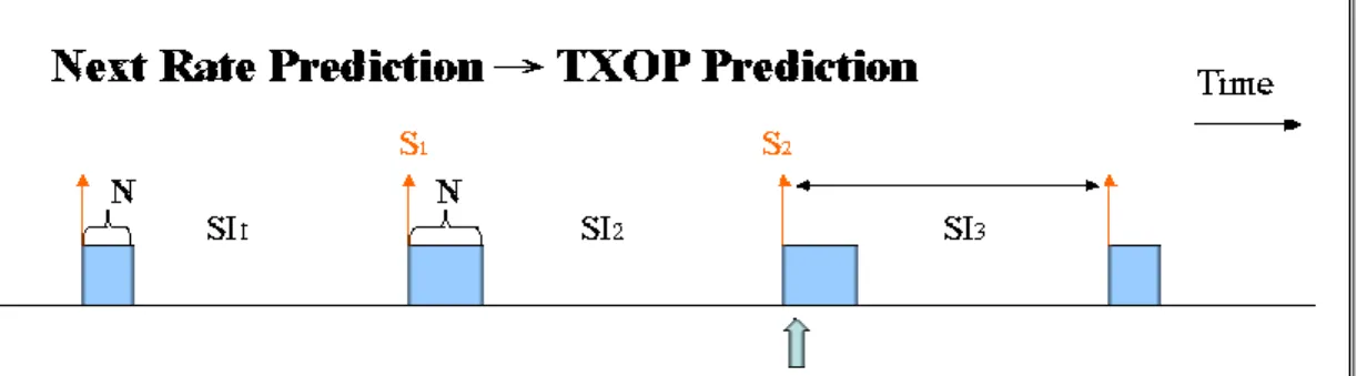
In this report, the challenge we face is that HC wants to know how much traffic will need to be cleared at the beginning of next service interval (SI). If the HC can predict the possible amount of traffic well, it can allocate suitable and enough time to the QSTA and achieve the goal of providing QoS. To forecast the queue level at the QSTA, the scheduler needs a mechanism to do rate estimation in order to track the possibly fluctuating data rate. In the following paragraphs, we will discuss some mechanisms of related works for the scheduling and propose a new method.
II.3 HCF Controlled Channel Access
Besides EDCA, IEEE 802.11e specifies another MAC function extension referred to as Hybrid Coordination Function (HCF) Controlled Channel Access. The HCCA mechanism uses a Hybrid Coordinator (HC) which is collocated with the QoS access point (QAP) of the QBSS and has higher priority to access the medium. The
HC can initiate frame exchange sequences and allocate TXOPs to itself or other QSTAs at any time when it senses the wireless medium (WM) has been determined to be idle for one PIFS period. In other words, it can provide limited-duration controlled access phase (CAP) at the contention period and initiate CFP after beacon frame for contention-free transfer of QoS data with higher priority than other non-AP QSTAs. The interval between frames during the CFP/CAP is one SIFS period, and therefore improves efficiency of the channel utilization.
Fig. 5 CFP, CAP, and CP periods in IEEE 802.11e [2]
The HC traffic delivery and TXOP allocation may be scheduled during the CP and any locally-generated CFP (generated optionally by the HC) to meet the QoS requirements of a particular traffic category or traffic stream. TXOP allocations can be based on the information obtained from negotiation of traffic specification (TSPEC). Through the TSPEC, the HC can have a QBSS-wide knowledge of the amounts of pending traffic belonging to different TS and/or TCs and schedule the traffic. When it is the time to poll the QSTA, HC should allocate suitable TXOP whose limit is notified at the QoS Control field of the QoS (+) CF-Poll frame. Within the polled TXOP a QSTA may initiate multiple frame exchange sequences when the remaining time is sufficient. Besides, the HCF protects the transmission during each CAP using
the virtual carrier sense mechanism. The use of this mechanism provides improved protection of the CFP, in addition to the protection provided by having all STAs in the BSS setting their NAVs to a value of CFP max duration at TBTT.
Element ID (13) Length (55) TS Info Nominal MSDU Size Maximum MSDU Size Minimum Service Interval Maximum Service Interval Inactivity Interval Suspension Interval Service Start Time Minimum Data Rate Mean Data Rate Peak Data Rate Maximum Burst Size Delay Bound Minimum PHY Rate Surplus Bandwidth Allowance Medium Time
Table 4 TSPEC element fields [2]
The IEEE 802.11e draft also provides an example scheduler in the annex as a reference design to meet the minimum performance requirements of different types of traffic. Each QoS station (QSTA) requiring strict and guaranteed QoS support can send an Add-Traffic-Stream (ADDTS) frame to do QoS request with the QAP. The QoS request frame includes a Traffic Specification (TSPEC) element that brings the information to notify the requirements of the traffic stream (TS). This simple scheduler uses the mandatory set of TSPEC parameters to generate a schedule; these parameters are Mean Data Rate, Nominal MSDU Size and Maximum Service Interval (MSI) or Delay Bound. If both MSI and Delay Bound are specified by the non-AP QSTA in the TSPEC, the scheduler uses the MSI to do calculation for the schedule. After gathering the requests, the QAP first determines the minimum value of all the MSI required by the admitted TSs. Then it will compute the highest sum-multiple of the beacon interval that is lower than the determined minimum of the MSI. This value will become the Scheduled Service Interval for all non-AP QSTAs with admitted streams. Therefore, the beacon interval is divided into multiple Sis and the admitted TS will be polled in a round-robin sequences during the CFP/CAP of each SI.
Fig. 6 Structure of service interval in referenced scheduler [12]
To calculate the allocated TXOP of specified TS, the QAP uses the following parameters: Mean Data Rate (ρ), Nominal MSDU Size ( L ), the Scheduled Service Interval ( SI ) derived above, Physical Transmission Rate (R), Maximum allowable Size of MSDU (M), and Overheads in time units (O). The Overheads in time is composed of IFS, ACKs and CF-Polls duration. The TXOP is calculated as follows. First, the scheduler need to calculate the number of MSDUs reached during a SI:
i i i SI N L
ρ
× = (3.1)Then the scheduler calculates the TXOP duration to clear the generated MSDUs:
max i i , , ,
(
,)
i
i i
N L M
TXOP O O O Poll SIFS ACK
R R
×
= + + =
(3.2)
The Admission Control Unit of the QAP will administer admissions of TSs. The ACU determines that the traffic stream can be admitted when the following inequality is satisfied:
1 1 k k i CP i TXOP TXOP T T SI SI T + = − +
∑
≤ (3.3) where k is the number of existing traffic streams in the schedule and k+1 is the index of the newly arriving stream. T is used to denote the duration of beacon interval andCP
T stands for the time used for EDCA traffic.
If the application is strictly constant bit rate (CBR), then the data rate will always follows the exchanged value of the mean data rate. Thus the TXOP duration derived can fulfill the requirement of traffic streams of this kind. However, when the type of application becomes variable bit rate (VBR), the data rate and packet size may fluctuate with time. When the rate is much higher then the mean value, using this scheme may possibly increase the packet delay or drops and then it cannot provide guaranteed QoS for the admitted traffic streams.
II.4 Proposed Algorithm
In this section, we propose our enhanced algorithm for estimating of data rate of specified traffic stream to be used for IEEE 802.11e HCCA scheduler for providing good delay and throughput guarantee. Our thought is motivated by the scheme of P-HCCA and presents some improvements to it.
In our scheme, we focus on the challenge that in IEEE 802.11e the QAP cannot instantaneously know the exact requirements of VBR traffic, like videoconference streams, during transmission time. If we estimate the possible TXOP duration only based on TSPEC parameters, as provided in referenced scheduler, QoS performance can be bad when the real rate is above mean value. Hence, under the inspiration from P-HCCA, we need a dynamical data rate estimating scheme with time to adjust the TXOP allocated to traffic streams of QSTAs.
II.4.1 Data Rate Estimation and Prediction
Different from P-HCCA, we estimate the mean data rate of a specified traffic over duration of service interval since the allocated TXOP aims to clear the traffic load that comes in a service interval. First, we determine the service interval for all traffic streams of each QSTA in the same way described in referenced scheduler. The QAP picks up the value, which is smaller than all of the MSI and is a sub-multiple of beacon interval, as service interval. Note here that the relation between MSI and Delay Bound is not specified in the upcoming standard of IEEE 802.11e, so we follow the guideline of SETT-EDD [13] to set the MSI as MSIi≤Di−MTDi for TS i when
generating the TSPEC in the upper layer of QSTAs. Then QAP will periodically initiate a CAP/CFP after duration of service interval, and all QSTAs should set their NAVs to the end of CAP/CFP duration each time it starts.
Fig. 7 Structure of the beacon interval
Then, we have to gather the queue length information at the beginning of current and the previous TXOP (in the previous service interval) for the TS and the amount of
MSDU size belonging to the TS that are sent during previous TXOP. Before these terms are fully collected, the QAP temporarily uses the mean value from negotiated TSPEC parameters. Notice that only VBR traffic, whose values of Mean Data Rate and Peak Data Rate items of TSPEC are not the same, needs to do rate estimation. From the following equation, we can have the total amount of traffic that comes in previous service interval:
2 1
0
( )
(
)
SI
i i i
Traffic
=
∫
M t
× =
dt
S
+ −
N
S
(II.1) where the M t means the MSDU size coming on time t, i( ) S2 is the queue size at the beginning of TXOP of current SI, S1 is the queue size at the beginning of TXOP of previous SI, and N is the total amount of data size sent in TXOP. Then the mean application data rate of previous service interval can be written as:i i Traffic Rate SI = (II.2) For the prediction of rate of next SI, we change the adjust factor to the ratio of amount of traffic come during previous service interval and the one before previous interval. The equation is as following:
□ ( ) ( ) ( ) , if
(
( ) & ( ))
0 ( ) i i i i i i Rate nNextRate n Rate n Rate n PreRate n
PreRate n
= × ≠ (II.3)
In the above equation, n is the index of service interval. If Rate ni( ) or PreRate ni( )
is equal to zero, we will use the mean data rate negotiated in the TSPEC element as
□ ( )
i
Fig. 8 The diagram of data rate prediction
II.4.2 TXOP Calculation
Having the new rate information, we can utilize it to predict the TXOP duration needed to be allocated. First we should estimate the corresponding number of packets belonging to traffic stream i:
□ , i next i i NextRate SI N M × = (II.4) Now, we derive the number of packets that will come in current service interval, and the traffic load should be cleared during next round of polling. The QAP then needs to calculate the required time corresponding to the number of traffic.
_ j next, 2
j
M
Next TXOP N SIFS ACK O R = ⋅ + × + +
∑
(II.5)Here we also utilize the method of aggregation. The term “Aggregation” means that if a QSTA has more than one admitted traffic stream in the schedule, each time when polling is performed the QAP will allocate TXOP considering all traffic streams belonging to the QSTA. In this way, it can reduce the number of polling packets and overheads and then make more efficient utilization of wireless medium.
Since the estimation may not always be very precise, we need a compensation mechanism to remedy the prediction error. The things we can utilize are the remaining time T after allocating all the polled TXOP to QSTAs in the CAP/CFP duration and r
the queue length information qie at the end of TXOP for traffic stream i. After collecting the queue length information, we do remaining time redistribution according to the weight which is derived from the proportion of e
i
q to the sum of all queue information: i
, if
0
e c r i e sum j j sumq
T
T
q
q
q
∀
=
×
=
>
∑
(II.6)This compensating time will also be combined with the TXOP allocated to QSTA to decrease the possible additional overheads of polling. Then the final TXOP allocated to QSTA will be:
_ j next, 2 jc
j
M
Next TXOP N SIFS ACK O T
R = ⋅ + × + + +
∑
(II.7)To implement the proposed scheme, the QAP should also maintain a polling list for all the admitted traffic streams of each QSTA and update the corresponding items when it receives the information:
Item Description
TID Traffic Stream’s ID
AID Association ID
Pre Mean Rate Mean data rate of the TS of the one before previous SI Next Mean Rate Mean data rate of the TS of next SI
Max SI Maximum Service Interval
MSDU MSDU Size
1
S -Queue-Len Queue length at the beginning of TXOP of previous SI
2
End-Queue-Len Queue length at the end of TXOP of previous SI Traffic Amount of traffic generated for TS during TXOP
Token Available token in the token bucket Depth Depth of the token bucket
Table 5 Polling list maintained by the QAP
After receiving the polled TXOP, the QSTA should simply seek for the queues of admitted stream from high priority to low priority to examine if there is a packet that needs to be sent. Only when the remaining time of polled TXOP is sufficient to send the next packet, can the QSTA utilize the time. If there is no packet that needs to be sent or the time is not sufficient to send the next packet, the QSTA should return a QoS Null packet to the QAP and give the control of medium back to it. The QAP can then poll the next QSTA in the round-robin polling sequence order. The CAP/CFP will end after the finish of polling sequence by an announcement of CF-End packet with zero duration to reset the NAV of all QSTAs. Then the medium is given back for contention.
There should also be a reserved time during service interval for contention-based medium access as it is needed for important management tasks (e.g., association of stations with the QAP during handover or initial connection).
II.4.3 Delay Analysis
Regarding the round-robin polling scheme, suppose that the queue length is qie
at the end of TXOP for traffic stream i. Let td denotes the time when the packets that come after this point cannot be transmitted during the TXOP in current SI, Tj
denotes the TXOP duration of traffic stream with index j, and t is the arrival time of the packet that we want to analyze. td can be written as the following equation:
1 e i i i d j j i q L t T
ρ
= =∑
− (II.8) For case 1, packet comes between 0 (referred to as the beginning of current SI) and td, and the delay of packet belonging to traffic stream i can be written as:0 1 1 ( ) ( ) i i i i i j j q L t d t T t R R
ρ
− = = − + + ∑
(II.9)In the above equation, qi0is the queue length of traffic stream i at the beginning of current service interval. For case 2, packet comes between td and SI (referred to as
the end current service interval), and the delay of packet belonging to traffic stream i can be written as:
1 1 ( ) ( ) ( ) i i d i j j t t d t SI t T R
ρ
− = − = − + + ∑
(II.10)Thus the maximum delay denoted by Di is obtained at the packet arrival time of td
and is equal to:
max ( ) ( ) e i i i i i d i t i q L D d t d t SI T
ρ
= = = − + (II.11) If the packet comes uniformly during the SI, we can estimate the mean latency as:1( 2 ) 2 e i i i i q L SI T
ρ
− + (II.12) For the possible case that the QAP allocates enough time for the traffic stream and the queue will be empty at the end of TXOP ( e 0i
q = ), since T is much smaller i
than SI, we can roughly know that the mean delay of simulation will be about half of the SI. In other cases, the result may vary a little for their traffic specification such as the arrival distribution. (Note that the delay including the waiting time till the next TXOP, queuing delay, and the transmission time of the packet.) Since TXOP duration
may be variable in different service interval for each TS of separate QSTA and the interval between successive service periods may not be exactly equal to SI, the full analysis should take these into consideration.
Part
III:
III.1 Simulation
The algorithms proposed in part I and II are implemented on ALTERA APEX Emulation Board, as shown in Fig. 9. We simulate the RTL code by using Quartus II 4.0 running on a 3.0 GHz Pentium 4 and the target device is the APEX EP20K600EBC652-1X. The expected purposes should be the good data control of EDCA and the better estimation of TXOP for HCCA. However, we are still debugging the code and do all we can to obtain the correct results. Thus, the report does not discuss the performance of our proposed algorithms since the bug is not fixed well.
Bibliographies
[1] IEEE Std. 802.11, "Wireless LAN Medium Access Control (MAC) and Physical
Layer (PHY) Specifications,” 1999.
[2] IEEE Std. 802.11e/D8.0, "Medium Access Control (MAC) Enhancements for
Quality of Service (QoS),” October 2003.
[3] D. Chen, D. Gu and J. Zhang, "Supporting Real-Time Traffic with QoS in IEEE
802.11e Based Home Networks", Consumer Communications and Networking
Conference (CCNC), pp. 205-209, January 2004
[4] S. Choi, JD Prado, S. Shankar and S. Mangold, "IEEE 802.11e contention-based
channel access (EDCF) performance evaluation," in Proc. IEEE ICC'03, vol. 2,
pp. 1151-1156, May 2003.
[5] T. S. Ho and K. C. Chen, "Performance evaluation and enhancement of the
CSMA/CA MAC protocol for 802.11 wireless LAN’s," in Proc. IEEE PIMRC,
Taipei, Taiwan, pp. 392-396, October 1996.
[6] L. Yang, "P-HCCA: A New Scheme for Real-time Traffic with QoS in IEEE
802.11e Based Networks," APAN Network Research Workshop 2004.
[7] Y. Xiao, H. Li, and S. Choi, "Protection and Guarantee for Voice and Video Traffic
in IEEE 802.11e Wireless LANs," Proc. of IEEE INFOCOM 2004.
[8] Y. Xiao and H. Li, "Voice and Video Transmissions with Global Data Parameter
Control for the IEEE 802.11e Enhance Distributed Channel Access," IEEE
Transactions on Parallel and Distributed Systems, vol. 15, no. 11, pp. 1041-1053, November 2004.
[9] Y. Xiao and H. Li, "Evaluation of distributed admission control for the IEEE
802.11e EDCA," IEEE Communications Magazine, vol. 42, pp. S20 - S24,
September 2004.
[10] D. Pong and T. Moors, "Call Admission Control for IEEE 802.11 Contention
[11] H. Fattah and C. Leung, “An Overview of Scheduling Algorithms in Wireless
Multimedia Networks,” IEEE Wireless Communications, vol. 9, no. 5, pp. 76--83,
Oct 2002.
[12] L.W. Lim, R. Malik & P.Y. Tan, “A QoS Scheduler for IEEE 802.11e WLANs,” Consumer Communications and Networking Conference, 2004.
[13] A. Grilo, M. Macedo, and M. Nunes, “A Scheduling Algorithm for QoS Support
![Table 3 QoS requirements of different kind of traffic [11]](https://thumb-ap.123doks.com/thumbv2/9libinfo/8594286.189891/21.892.147.747.591.845/table-qos-requirements-different-kind-traffic.webp)
![Fig. 5 CFP, CAP, and CP periods in IEEE 802.11e [2]](https://thumb-ap.123doks.com/thumbv2/9libinfo/8594286.189891/23.892.135.760.428.628/fig-cfp-cap-cp-periods-ieee-e.webp)
![Table 4 TSPEC element fields [2]](https://thumb-ap.123doks.com/thumbv2/9libinfo/8594286.189891/24.892.42.864.226.397/table-tspec-element-fields.webp)
![Fig. 6 Structure of service interval in referenced scheduler [12]](https://thumb-ap.123doks.com/thumbv2/9libinfo/8594286.189891/25.892.137.757.146.545/fig-structure-service-interval-referenced-scheduler.webp)