一個輕量化無線擷取點協定的實作
60
0
0
全文
(2) 一個輕量化無線擷取點協定的實作 An Implementation of Light Weight Access Point Protocol. 研 究 生:林鈺翔. Student:Yu-Hsiang Lin. 指導教授:簡榮宏. Advisor:Rong-Hong Jan. 國 立 交 通 大 學 資 訊 科 學 研 究 所 碩 士 論 文. A Thesis Submitted to Institute of Computer and Information Science College of Electrical Engineering and Computer Science National Chiao Tung University in partial Fulfillment of the Requirements for the Degree of Master in. Computer and Information Science June 2004 Hsinchu, Taiwan, Republic of China. 中華民國九十三年六月.
(3) 一個輕量化無線擷取點協定的實作. 研究生:林鈺翔. 指導教授:簡榮宏 博士. 國立交通大學資訊科學研究所. 摘. 要. 傳統無線區域網路架構已經被廣泛的使用多年,其主要是由多功能的智慧型 擷取點及第二層的網路協定交換器所構成,藉以此建構出無線區域網路的骨幹架 構。然而,這種架構存在著許多的缺點,包含較高的網路管理及網路建構成本,整體 性的效能低落等等。假若此傳統無線區域網路架構和 IEEE 802.1x 整合使用,一旦 使用者在不同的擷取點之間快速的移動,那麼換手延遲的時間將無法滿足一些即 時性的多媒體應用程式的需求。因此在本篇論文中,我們將建構一個以及輕量化 擷取點為基礎,且為集中式管理的無線區域網路架構來改進傳架構上的缺失。另 外,本文也會提出一個改良式的 IEEE 802.1x 認證程序來減少換手的延遲,而實驗 證實我們的方法比原有的方法要好。. i.
(4) An Implementation of Light Weight Access Point Protocol. Student:Yu-Hsiang Lin. Advisor:Dr. Rong-Hong Jan. DEPARTMENT OF COMPUTER AND INFORMATION SCIENCE NATIONAL CHIAO TUNG UNIVERSITY. Abstract Traditional WLAN architecture has been used for several years. It consists of intelligent access point and layer 2 switch and uses as a WLAN backbone infrastructure. However, it has many drawbacks such as high overhead of network management, high construction cost and low performance. Once traditional WLAN architecture works together with the IEEE 802.1x mechanism and the mobile host moves between different access points quickly, the handoff delay will not meet the requirement of real-time multimedia application. In this thesis, we will construct a centralized WLAN architecture based on the Thin AP architecture to improve the weak points of the traditional WLAN architecture. A modified IEEE 802.1x authentication procedure is also presented to decrease the handoff delay, and the experiment shows that the novel mechanism is better than the original one.. ii.
(5) Contents 1 Introduction. 3. 1.1. Traditional APs . . . . . . . . . . . . . . . . . . . . . . . . . . . . . . . . .. 4. 1.2. ”Thin” Access Point Solutions . . . . . . . . . . . . . . . . . . . . . . . . .. 8. 2 Background. 12. 2.1. IEEE 802.1X architecture . . . . . . . . . . . . . . . . . . . . . . . . . . . 12. 2.2. HostAP . . . . . . . . . . . . . . . . . . . . . . . . . . . . . . . . . . . . . 15. 2.3. Light Weight Access Point Protocol (LWAPP) . . . . . . . . . . . . . . . . 18. 3 System architecture. 20. 3.1. System overview. . . . . . . . . . . . . . . . . . . . . . . . . . . . . . . . . 20. 3.2. Thin access point architecture . . . . . . . . . . . . . . . . . . . . . . . . . 25. 3.3. Access router architecture . . . . . . . . . . . . . . . . . . . . . . . . . . . 30. 3.4. Modified IEEE 802.1x authentication procedure . . . . . . . . . . . . . . . 39. 4 Performance evaluation. 41. 4.1. Environment of evaluation experiment . . . . . . . . . . . . . . . . . . . . 41. 4.2. IEEE 802.11 authentication and association procedure . . . . . . . . . . . 42. 4.3. IEEE 802.1x authentication procedure . . . . . . . . . . . . . . . . . . . . 44. 5 Conclusion. 50. 1.
(6) List of Tables 1.1 1.2 1.3. The capital expense of constructing centralized and distributed wireless LAN environment . . . . . . . . . . . . . . . . . . . . . . . . . . . . . . . .. 6. The operation expense of constructing centralized and distributed wireless LAN environment . . . . . . . . . . . . . . . . . . . . . . . . . . . . . . . .. 7. The total cost of constructing centralized and distributed Wireless LAN architecture. . . . . . . . . . . . . . . . . . . . . . . . . . . . . . . . . . . .. 7. 2.
(7) List of Figures 1.1. Traditional WLAN architecture . . . . . . . . . . . . . . . . . . . . . . . .. 1.2. The Thin AP architecture. . . . . . . . . . . . . . . . . . . . . . . . . . . . 11. 2.1. The IEEE 802.1x model. . . . . . . . . . . . . . . . . . . . . . . . . . . . . 13. 2.2. How does the user space daemon works with HostAP driver to emulate an access point . . . . . . . . . . . . . . . . . . . . . . . . . . . . . . . . . . . 16. 3.1. The system architecture . . . . . . . . . . . . . . . . . . . . . . . . . . . . 21. 3.2. A message sequence chart to demonstrate that how does the authentication and association procedure works on our architecture. . . . . . . . . . . . . 25. 3.3. A message sequence chart to demonstrate that how does the IEEE 802.1x model works on our architecture. . . . . . . . . . . . . . . . . . . . . . . . 26. 3.4. The main flowchart of thin AP. . . . . . . . . . . . . . . . . . . . . . . . . 29. 3.5. The main flowchart of access router. . . . . . . . . . . . . . . . . . . . . . . 34. 3.6. The module of handling RADIUS packet. . . . . . . . . . . . . . . . . . . . 35. 3.7. The module of handling management of access points. . . . . . . . . . . . . 36. 3.8. The module of handling the IEEE 802.11 frame from mobile station. . . . . 38. 3.9. A message sequence chart demonstrates the modified IEEE 802.1x authentication procedure. . . . . . . . . . . . . . . . . . . . . . . . . . . . . . . . 40. 4.1. Total time of IEEE 802.11 handoff in two architectures: single STA handoff between two different access points. . . . . . . . . . . . . . . . . . . . . . . 42. 4.2. Handoff time of each station in our architecture: two STAs execute IEEE 802.11 handoff between two different access points. . . . . . . . . . . . . . 43 3. 5.
(8) 4.3. The time of IEEE 802.11 handoff in our architecture: total handoff time and difference of handoff time of two stations. . . . . . . . . . . . . . . . . 44. 4.4. Handoff time of each station in traditional WLAN: two STAs execute IEEE 802.11 handoff between two different access points. . . . . . . . . . . . . . 45. 4.5. The time of IEEE 802.11 in handoff traditional WLAN: total handoff time and difference of handoff time of two station. . . . . . . . . . . . . . . . . . 46. 4.6. Total time of IEEE 802.1x handoff in two architectures: single STA handoff between two different access points. . . . . . . . . . . . . . . . . . . . . . . 47. 4.7. Handoff time of each station in our architecture: two STAs execute IEEE 802.1x handoff between two different access points. . . . . . . . . . . . . . 47. 4.8. The time of IEEE 802.1x handoff in our architecture: total handoff time and difference of handoff time of two stations. . . . . . . . . . . . . . . . . 48. 4.9. Handoff time of each station in traditional WLAN: two STAs execute IEEE 802.1x handoff between two different access points. . . . . . . . . . . . . . 48. 4.10 The time of IEEE 802.1x in handoff traditional WLAN: total handoff time and difference of handoff time. . . . . . . . . . . . . . . . . . . . . . . . . . 49. 4.
(9) Chapter 1 Introduction The IEEE 802.11b Wireless LAN are becoming popular in hot spot areas such as convention centers, airports, shopping malls, and etc. This is attributed to its convenience from fast accessing to network, achievement of mobility and high transport rate. There are more and more enterprises or campuses construct Wireless LAN environment to make users a convenient way to access to internet. But the traditional Wireless LAN architecture such as intelligent access point and distributed Wireless LAN architecture are not suitable for some applications. For example, as far as the traditional Wireless LAN architecture works together with the IEEE 802.1x [1] model is concerned, if the mobile host moves between different access points quickly, the handoff delay will not meet the requirement of real-time multimedia application.. In order to overcome the drawbacks of the traditional Wireless LAN architecture, we have to point them out and propose a new Wireless LAN architecture working together with IEEE 802.1x model to improve the performance, manageability and security. Addi-. 3.
(10) tionally, an improved handoff policy will be presented to minimize the handoff latency. First of all, we will inspect the traditional AP architecture and find the drawbacks of this architecture. Section 1.1 describes the architecture and points out the disadvantages of traditional access point architecture. Section 1.2 introduces a novel access point architecture (thin AP) which we will use in the architecture we present in this thesis.. 1.1. Traditional APs. Traditional APs (also called FAT APs) architecture have been used for many years. Instead of providing widespread wireless connectivity, they are originally invented to provide wireless connectivity at specific points in a building or place, such as conference hall or a cafeteria. However, enterprises or campuses usually construct Wireless LAN with a lot of access points to provide good connectivity to users. With the growing up of access points, the drawbacks of traditional APs become a critical problem.. Traditionally, most access points, especially those for enterprises, are intelligent than what the 802.11 standard provides. For example, AP for enterprise will implement advanced functions to enhance security, management, and performance. They are standalone devices that handle all Wireless LAN functionality, ranging from physical layer to security relative issue, such as wireless access, wireless encryption, secure mobility and user management. Many of these APs also handle critical network functions such as routing, IP tunneling, 802.1Q trunking, network address translation (NAT) and even virtual. 4.
(11) private network (VPN) functions. For example, an AP uses complicated access control mechanisms to provide better security than what the 802.11 standard contains.. Mobile station. FAT AP. Layer 2 switch x. 1. x. 8. x. 9. x. 2. x. 3. x. 0 1. x. 4. x. 1. 1. x 1. 2. 6. x. x. 7. x. 1. x. 8. x. 9. x. 2. x. 3. x. 0 1. x. 4. x. 1. 1. x 1. 2. 6. x. x. t e. 7. r e. n. C. 8. 9. 1. 2. 3. 1. 0. 1. 1. 4. 5. 6. 2. h t. 7. E. A. A. x 5 B. x 5. Figure 1.1: Traditional WLAN architecture. These ”fat” APs (or ”thick”, ”smart” APs, see figure1.1) connect to an layer 2 switch and provide a Wireless LAN backbone infrastructure. The switche in this case usually does not have any features about enhancing wireless communications which is necessary for supporting real-time multimedia applications (such as voice over Wireless LANs). For example, because the traditional wireless LAN architecture do not support mobility between APs unless they complete the re-authentication procedure. When IEEE 802.1x model is used to achieve user authentication and a mobile station handoff from current AP to another, the mobile station will authenticate to the new AP and RADIUS [2]. 5.
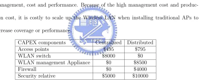
(12) server, If the new AP and the old AP do not have feasible communication mechanism (such as the previous access point buffer the data of the mobile station and send to new access point when handoff occur), handoff delay will cause data transmission lag and the roaming operation will not be smooth.. Fat APs are stand-alone devices and must be configured and managed independently. Therfore, they do not allow to scale to hundreds or thousands of access points in network. However, an enterprise usually uses dozens or even hundreds of traditional APs to construct a wireless LAN environment and these traditional APs are relatively expensive than the ”thin AP” which is a novel architecture and it has the advantage on network management, cost and performance. Because of the high management cost and production cost, it is costly to scale up the Wireless LAN when installing traditional APs to increase coverage or performance.. Centralized CAPEX components $495 Access points $8000 WLAN switch $0 WLAN management Appliance $0 Firewall $5000 Security relative. Distributed $795 $0 $8500 $4000 $10000. Table 1.1: The capital expense of constructing centralized and distributed wireless LAN environment. Table 1.1 and Table 1.2 show the total cost of constructing the Wireless LAN environment with fat AP(distributed architecture) and thin AP(centralized architecture). Obviously, each architecture has its advantages over different application area. For ex6.
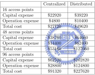
(13) Centralized OPEX components $0 AP planning and configuration $250 AP installation $0 AP provisioning $0 RF spectrum management $50 AP managemence. Distributed $200 $250 $200 $200 $250. Table 1.2: The operation expense of constructing centralized and distributed wireless LAN environment ample, distributed architecture has the advantage that it does not need additional device except access point its-self, and centralized architecture has the lower cost advantage in configuration and management.. 16 access points Capital expense Operation expense Total cost 48 access points Capital expense Operation expense Total cost 96 access points Capital expense Operation expense Total cost. Centralized. Distributed. $22920 $4800 $27720. $39220 $10400 $49620. $38760 $14400 $53160. $64660 $62400 $127060. $62520 $28800 $91320. $102820 $124800 $227620. Table 1.3: The total cost of constructing centralized and distributed Wireless LAN architecture.. In table 1.3, we can find out that when the number of access point grows up, the cost of the Wireless LAN within fat AP architecture are more than the one within thin AP. However, when we construct a Wireless LAN environment in enterprise or campus, we often need mass of access point to achieve throughout coverage. So, the conventional. 7.
(14) fat AP architecture is not suitable for the Wireless LAN environment over enterprise or campus.. In addition, a standard AP approach is costly to migrate to newer technologies. In some cases, a company can merely upgrade the firmware of the AP to begin implementing modifications, such as using WPA .However, the deployment of some technologies, such as AES will likely require replacing the APs (AES requires its own encryption chip). Consequently, the thick AP can be expensive to support.. As long as the management of access points is concerned, each AP autonomously manages all data and control frames and must be managed as an autonomous device in turn. APs have lots of configuration parameters that operational support software must interface with. This generates a significant amount of over head traffic over the network, which can decrease the performance of primary applications.. Therefore, we use a new architecture to solve the problem with traditional AP architecture.. 1.2. ”Thin” Access Point Solutions. Some manufacturers of Wireless LAN equipment, such as Legra and Airespace, minimize the intelligence of an AP and centralize the intelligence of the network in the switch instead, so called ”thin AP architecture”. In a thin AP architecture, as shown in figure. 8.
(15) 1.2, APs are little more than radio-for-wire media converter, communicating with a single centralized intelligent point in the network core (access router). The intelligent control point (access router) handles all aspects of management or security, such as 802.1X user authentication, wireless encryption, secure mobility, the management of mobile station or AP and so on. The access router configures and manages the access points, which cannot function as standalone units and must cooperate with access router. With this approach, relatively simple access points can share the features that enhance performance of wireless access, make the management cost-effective and efficient and decrease the capitalized cost of manufacturing those access points.. Because most of the configuration is centralized in the wireless switch (access router), which reduces management functions from operating over the Wireless LAN. The access point with thin AP architecture will have more resource to handle the control frame or data frame of mobile station that will enhance the performance of wireless access. Furthermore, an administrator can interact directly with the access router from the more familiar wired side of the network. The central nature of the access router makes it an excellent platform for managing the network.. Besides, functions implemented in the thin APs are not more than the 802.11 standard, thin APs are generally cost-less. This can reduce the total cost of ownership (TCO) of constructing a Wireless LAN environment because of lower capitalized cost and lower management cost.. 9.
(16) Furthermore, the access router (wireless switch) optimizes performance of the network. Roaming handoffs are much faster than with conventional switch, which makes it more practical to effectively support real-time multimedia applications.. Therefore, we will construct a centralized wireless LAN architecture based on the Thin AP architecture to fix the faults of the traditional wireless LAN architecture and we will use the architecture to work together with the IEEE 802.1x model. In chapter 2, we discuss some background knowledge of construction our system architecture. In chapter 3, we demonstrate how we implement the system architecture which we present in this thesis. Chapter 4 shows the result of performance evaluation and Chapter 5 is the conclusion of this thesis.. 10.
(17) Mobile station Thin AP. Access router I. D. C. Figure 1.2: The Thin AP architecture.. 11.
(18) Chapter 2 Background In this chapter, we will introduce some protocols which will be used in our system architecture. In section 2.1, we describe the IEEE 802.1x architecture which is an alternative authentication scheme suggested by IEEE to overcome the drawbacks of the existing authentication schemes. In section 2.2, we will introduce a linux driver for wireless LAN card so called HostAP [3] and explain how the user space daemon works with it to emulate an access point. In section 2.3, we describe the light weight access point protocol, which is a draft of IETF. It makes access router to centrally manage the access points more convenient.. 2.1. IEEE 802.1X architecture. The IEEE 802.1x standard is designed to enhance the security of wireless LAN which follows the IEEE 802.11 standard. It provides an authentication framework for wireless LANs, allowing a user to be authenticated by a central authority (RADIUS server). In. 12.
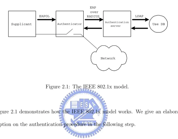
(19) IEEE 802.1x model, a network-to-client authentication mechanism utilizing EAP [4] (Extensible Authentication Protocol) is used as the encapsulation protocol for upper-layer authentication information. EAP over RADIUS. EAPOL Supplicant. LDAP Authentication server. Authenticator. Use DB. Network. Figure 2.1: The IEEE 802.1x model.. Figure 2.1 demonstrates how the IEEE 802.1x model works. We give an elaborative description on the authentication procedure in the following step.. (1) The user (a laptop or other wireless device) has software (so called the supplicant) that understands IEEE 802.1x. If the user wants to connect to a network, the supplicant will request the network through the Extensible Authentication Protocol (EAP) over 802.1X for grant of network access. (2) The point of access to the network is called the ”authenticator”, which is a Wireless Access Point (or an Ethernet switch in case we are dealing with a fixed network). The access point plays a role of repeater and does not record the authentication 13.
(20) information of users. However, it sends the authentication request to an ”authentication server”, which is usually a RADIUS server. (3) In the database of RADIUS server, or a database connected to it, the RADIUS server looks up the user, the type of authentication to be used and his permissions. An institution can either choose to use Username/Password, Certificates (either on a chip card, a USB token or as a file) or methods to be developed. It is even possible to assign a different authentication type to every user, which is attributed to the modularity of 802.1X and EAP. (4) The entire authentication and authorization (A&A) process is encrypted, which makes it hard to intercept passwords or ID’s. If the user enters the right credentials, the RADIUS-server tells the AP to open the connection for the user (offer service to the mobile station), and gives both the AP and the user temporary WEP keys. This means that the entire session of the user is encrypted as well.. However, the authentication procedure of IEEE 802.1X may impact the performance of network. Because the mobile station has to re-authenticate to access point after handoff and then re-authenticate to the RADIUS server, we should consider the influence due to the complete authentication procedure when handoff occurs.. In the IEEE 802.1x model, it not only needs a long time to send the RADIUS packet to RADIUS server due to the RADIUS server usually locates far away from access point but a complete authentication procedure also needs to exchange RADIUS messages between 14.
(21) access point and RADIUS server for several times. As a result, mobile station needs to wait for a long time until the authentication procedure is complete when it moves around between different access points. It is reasonable that the handoff delay of the authentication mechanism need to be as small as possible to make the handoff delay meet the requirement of the real-time application. Unfortunately, since RADIUS servers are located at locations far away from the AP, long distance packet transmission will not make current handoff schemes meeting all requirements of the real-time multimedia applications. Therefore, we need a novel Wireless LAN architecture to decrease the handoff latency causing by the long distance packet transmission.. 2.2. HostAP. HostAP is a Linux driver for wireless LAN cards based on Intersil’s Prism2/2.5/3 chipset. The driver supports a so called HostAP mode. In the HostAP mode, Intersil’s station firmware for Prism2 chipset takes care of time critical tasks like beacon sending and frame acknowledging, but leaves other management tasks to HostAP driver. The HostAP driver takes care of IEEE 802.11 management functions in the host computer and acts as an access point. It has various features for development debugging and for researching IEEE 802.11 environments.. In general, HostAP can be divided into two parts. One part is driver, and the other part is hostapd, a user space daemon. The driver implements basic functionality needed. 15.
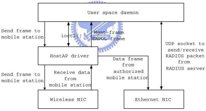
(22) to initialize and configure Prism2-based cards, to send and receive frames, and to gather statistics. The hostapd implements the IEEE 802.11 authentication and IEEE 802.1x Authentication procedure. By executing hostapd daemon, system has the ability to handle the IEEE 802.1x frames and RADIUS packets and plays a role as a authenticator in IEEE 802.1x protocol. In this way, system can acts as an access point and provide IEEE 802.1x authentications.. In the architecture we present in this thesis, we use the HostAP driver as the platform to implement the thin access point architecture. We also use the driver to emulate the mobile station in performance evaluation.. User space daemon. Send frame to mobile station. ioctl(). Mgmt frame EAPOL frame. HostAP driver. Send frame to mobile station. Data frame from authorized mobile station. Receive data from mobile station Wireless NIC. UDP socket to send/receive RADIUS packet from RADIUS server. Ethernet NIC. Figure 2.2: How does the user space daemon works with HostAP driver to emulate an access point. 16.
(23) Figure 2.2 shows how does the user space daemon work with HostAP driver to emulate an access point. The following gives a detail explain for figure 2.2.. 1. User space daemon can use the ioctl() function to interact with HostAP driver, such as setting the maximum transfer unit(MTU), enabling the IEEE 802.1x model and get the statistics. 2. When HostAP driver receives an IEEE 802.11 frame from mobile station, it will filter the data frame and send the management frame and EAPOL frame to user space daemon. 3. If the IEEE 802.1x model is enabled, HostAP driver will check weather the destination or source of data frame is authorized by RADIUS server. If the data frame comes from wireless NIC, HostAP will check the source of the data frame; otherwise, it will check the destination of the data frame. If the destination or source is authorized, HostAP driver will push the frame to the bridge and send it to the destination directly. The data frame will not be sent to user space daemon for enhancing the wireless access performance. 4. User space daemon can send the response of IEEE 802.11 management frame or EAPOL frame to mobile station through HostAP driver. In this way, user space daemon plays a role as access point in IEEE 802.11 architecture and authenticator in IEEE 802.1x model.. 17.
(24) 2.3. Light Weight Access Point Protocol (LWAPP). In this thesis, the cooperation between access point and access router (wireless switch) will be achieved by Light Weight Access Point Protocol (LWAPP) [5], which is currently in draft status at the IETF (Internet Engineering Task Force). LWAPP is originally meant to be the open, standard protocol for access point management. It outlines the rules for switches or routers to control a group of IEEE 802.11 wireless LAN access points.. The idea for this new protocol is based on the fact that wireless access points usually work as network access servers, and they are assigned with IP address. As a result, an access point is not just a Layer 2 device, it also has some other abilities of layer 3 device. In fact, the access points we use today usually have intelligence beyond what the 802.11 standard provides. This will make both of the capitalized cost of constructing Wireless LAN and operation expense of managing access points or mobile stations unacceptable.. Once deployed, the first step of LWAPP is to reduce the needed filter and policy processing in an access point. Those works will be centralized and any changes will be broadcast to the access points. And then, LWAPP designers will also use the same centralized management architecture to deal with traffic management, authentication, encryption, and policy enforcement. Finally, LWAPP will provide a generic encapsulation and transport mechanism so that one vendor’s LWAPP console can work together with multiple vendors’ LWAPP-enabled access points.. 18.
(25) At the same time, as management is centralized, LWAPP-equipped access points would have more memory and processor power so that they could run system access policies or manage traffic. As a result, the access point can provide much better service to mobile station than a traditional access point.. With the emergence of novel and efficient access points, and a lot of functions moved upstream into a wireless LAN switch. LWAPP could radically simplify the deployment and management of wireless LAN networks.. The LWAPP identifies three goals:. (1) Reducing the amount of protocol code running on a light weight access point. Let access point spend more processing resource on wireless access in stead of filtering and routing to increase the transmission performance. (2) Centralizing the work of bridging, forwarding and policy enforcement on a wireless LAN. Move these function to access router. (3) Creating a generic encapsulation and transport mechanism that will increase the interoperability ability among different brands.. In this thesis we will use thin AP architecture based on IEEE802.1x model and LWAPP to enhance the performance of access points and security for users, increase manageability of mobile station an access points. An improved handoff policy will also be presented to minimize the handoff latency to meet the requirement of real-time multimedia application. 19.
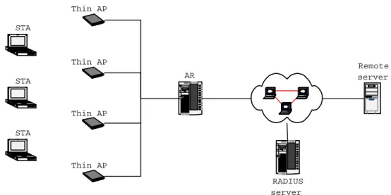
(26) Chapter 3 System architecture In this chapter, we will introduce the architecture we implement. The architecture includes three major components: thin access point, access router and IEEE 802.1x authentication procedure. We will introduce the overall architecture first and inspect the three components one by one. Section 3.1 is the overview of system architecture. Section 3.2 is the implementation of Thin AP. Section 3.3 is the implementation of AR. In section 3.4, we introduce the modified IEEE 802.1x authentication procedure which will decrease the handoff delay when user moves around different access points.. 3.1. System overview. In this section, we will give a comprehensive introduction of our system. Fig 3.1 illustrates the system architecture we present in this thesis. Section 3.1.1 makes a description of every major component of the system architecture. Section 3.1.2 gives two message sequence chart to illustrate how the system is operating.. 20.
(27) Thin AP STA. Thin AP. Remote server. AR. STA D I. C. Thin AP STA I. D. C. Thin AP RADIUS server. Figure 3.1: The system architecture 3.1.1 Component description. In the system architecture, there are four major components: STA (mobile station), Thin AP (thin access point), AR (access router) and RADIUS server. The following gives a description of the each component.. 1. STA (mobile station). STA is the users with portable device such as laptop or personal digital assistant, they must associate to access points to gain network access capability. Because the devices are portable and well equipped, users may move between different access points and use the device to execute some real-time multimedia application. The handoff delay and high traffic will case the quality of service does not fulfil the user. For example, if the user is moving around and using voice over wireless LAN to talk 21.
(28) with another one, the unstable service quality (which is due to packet lost) may cause the conversation unsmooth. Therefore, the network architecture must be well designed to support the requirement of service quality of STA. 2. Thin AP. The Thin AP is different from traditional one which we have discussed in chapter 1. It does not have many functions but just plays a role as layer 2 repeater. Most of the functions in traditional access point such as IEEE 802.11 management function, IEEE 802.1x mechanism and user management have been moved to AR. In addition, a Thin AP can not operate individually, it must cooperates with and be managed by AR. 3. AR (access router). AR plays a role as network manager, it not only handles the authentication and authorization of mobile stations but also manages all thin access points which belong to it. AR cooperates with a RADIUS server to achieve user authentication. In addition, thanks to the centralized architecture, AR can gather the statistics from every access point at its own will. With the statistics and information of all mobile station, AR can configure every access point to achieve network management and load balance easily. In other words, AR can optimize the network performance dynamically.. 22.
(29) In addition, AR also has the function to manage the IEEE 802.11 data frame of mobile station. If the AR receives the IEEE 802.11 data frame of a mobile station by the way of an access point, it will check weather the source of the frame is authorized or not. Only the frame of authorized station will be sent to destination. Otherwise, it will be dropped. Similarly, AR will check the frame which is coming from the external network. If the destination of the frame is authorized, the frame will be sent to the mobile station. 4. RADIUS server. RADIUS (Remote Access Dial In User Service) server is used to authenticate users by checking the identity and password of user. Because of the nature of wireless access, data is transferred by radio frequency. As a result, the user data is exposed to the adversary and the important information in the packet may be stolen easily. In addition, any mobile station can gain the network access capability if the wireless network does not implement user authentication. To protect the rights of legitimate users, RADIUS protocol is needed to achieve user authentication and enhance the security of data transfer. When a mobile station moves into the coverage of an access point, it will authentication and association to AR through AP, and authenticates to RADIUS server immediately. IF the mobile station is authorized by the RADIUS server, AR will ask AP to provide service (usually the network access capability) for mobile station.. 23.
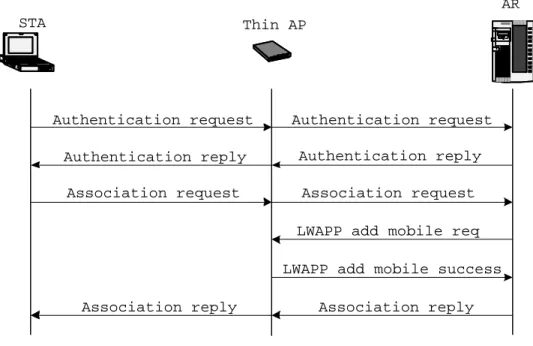
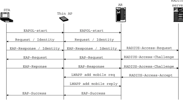
(30) 3.1.2 Message sequence chart of system. In this section we give two message sequence charts to illustrate how the system is working.. First of all, we will show how the access router manages the mobile stations by figure 3.2. The original IEEE 802.11 authentication procedure has been divided into two parts. The function of managing mobile stations has been drew out from access point and moved to access router. Access point just plays a role as a layer 2 repeater, it will relay the request from mobile station to access router or relay the response from access router to mobile station. If mobile station has associated, access router will ask the access point to record the information of the mobile station for future management procedure. As a result, access router can manage mobile stations by the way of access points. Figure 3.3 makes a description about how our system architecture works with the IEEE 802.1x model. As we have discussed in figure 3.2, access point plays a role as a layer 2 repeater. It will relay the EAPOL packets between mobile station and access router. The message sequence chart is the same with the original IEEE 802.1x model except the authenticator is not access point anymore but access router. Access router has the duty to maintain the state of mobile station during authentication procedure to help mobile station accomplishes the authentication. In addition, access router will ask the access point to provide the service to mobile station if the mobile station is authorized by RADIUS server. 24.
(31) AR STA. Thin AP ID. Authentication request. C. Authentication request Authentication reply. Authentication reply Association request. Association request. LWAPP add mobile req LWAPP add mobile success Association reply. Association reply. Figure 3.2: A message sequence chart to demonstrate that how does the authentication and association procedure works on our architecture. A modified IEEE 802.1x authentication procedure, moreover, is presented to decrease the response time of authentication procedure. In other word, we can minimize the handoff delay when a mobile station moves from an access point to another access point. We will discuss this procedure in detail in section 3.4.. 3.2. Thin access point architecture. In this section, we will show the implementation methodology of thin AP. First of all, we will describe the platform which we use to implement the thin access point architecture. Then we will describe the main tasks of the thin AP. Finally, we will describe the main state machine of thin AP and the major function of every state individually will be shown. 25.
(32) RADIUS server. AR STA. D I. C. Thin AP. EAPOL-start. EAPOL-start. Request / Identity. Request / Identity EAP-Response / Identity. EAP-Response / Identity. EAP-Request. EAP-Request. EAP-Reponse. EAP-Response. LWAPP add mobile req. RADIUS-Access-Request RADIUS-Access-Challenge RADIUS-Access-Challenge RADIUS-Access-Accept. LWAPP add mobile reply EAP-Success. EAP-Success. Figure 3.3: A message sequence chart to demonstrate that how does the IEEE 802.1x model works on our architecture. 3.2.1 Development environment. We use InterEpoch’s access point as the platform to implement the thin access point. This access point is based on Intersil’s Prism2.5 chipsets which can work with the HostAP driver to emulate the access point. Therefore, we can implement the thin access point architecture by receiving and transmitting the IEEE 802.11 frame through the driver. Due to HostAP driver does not take care of bridging between wireless and wired networks, it has to be implemented using external software if this access point feature is required. Thus, we installed bridge-utils-0.9.6-1 to support bridge functionality.. 3.2.2 Overview 26.
(33) For each AP in thin AP architecture, it has four major tasks:. 1. Receive the frame from mobile station (such as IEEE 802.11 management frame, IEEE 802.11 data frame and IEEE 802.1x packet) and send it to access router. 2. Receive the frame from access router (such as IEEE 802.11 management frame, IEEE 802.11 data frame and IEEE 802.1x packet) and send it to mobile station. 3. Receive the LWAPP packet from access router and execute the corresponding function according to the command in the LWAPP packet.. a. Add or delete mobile station to kernel driver:. When a mobile station associates to an access router, the access router will ask the access point to record the information of the mobile station for future operation. On the contrary, if a mobile station disassociates to an access router, the access router will ask the access point delete the information of the mobile station.. b. Offer or do not offer network service to a mobile station:. When a mobile station is authorized by a RADIUS server, access router will ask access point to offer network service to the mobile station. On the contrary, access point will disable the network access capability of a mobile station if the mobile station is not authorized by a RADIUS server.. c. Check the activity of mobile station: 27.
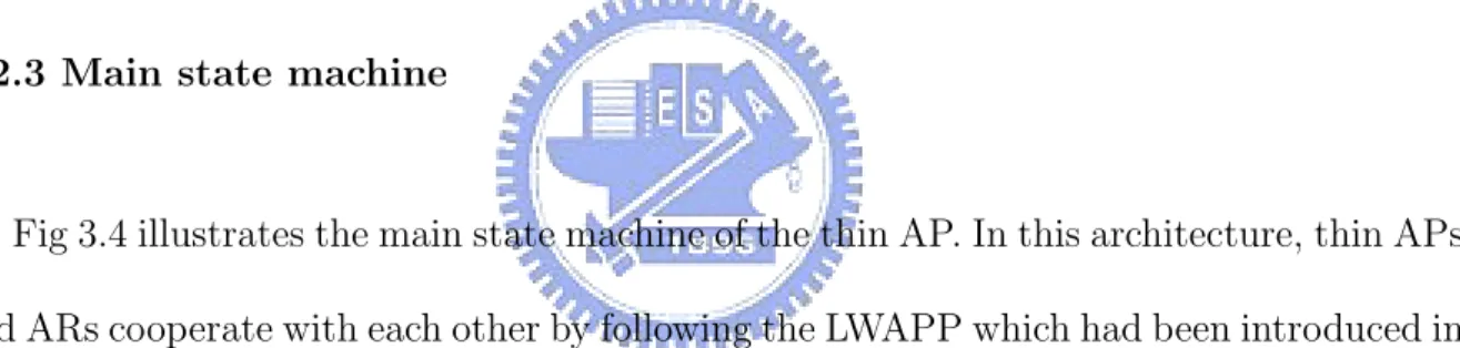
(34) To prevent a inactive mobile station from occupying the system resource, access router will ask access point to check the activity of the mobile station. If the mobile station is inactive, access point will stop providing the service to the mobile station.. d. Reset:. If some critical function (such as download new firmware from access router) has been executed, access router will ask the access point to restart itself. 4. Send the statistics to access router periodically. Access router can optimize the network performance by configuring every access point according to the statistics.. 3.2.3 Main state machine. Fig 3.4 illustrates the main state machine of the thin AP. In this architecture, thin APs and ARs cooperate with each other by following the LWAPP which had been introduced in chapter 2. For this reason, LWAPP relative functions are in the majority of the functions of thin AP. The following steps describe Figure 3.4 in more detail.. 1. When access point starts, it enters Idle state immediately and waits for a while for entering the Discovery state. 2. Then it will enter Discovery state to search how many access routers are available in 28.
(35) Reset. Idle. Time out. Sulking. Discovery. success. Running. failure. failure. Join. Key update. success. Configure success. Figure 3.4: The main flowchart of thin AP. this subnet. If there is no available access router, access point will enter Sulking state for a while and enter Discovery state again. 3. While access point receives the information of access router, access point will enter Join state and choose a appropriate access router to join. If the join action is success access point will enter Configure state. Otherwise, it will return to Discovery state to get information of access routers again. 4. In the Configure state, access point will send its configuration and hardware limitation of itself to access point. If the access router accepts the configuration and limitation, it sends the response back to configure the access point to optimize the performance of entire network. Otherwise, access point will return back to Discovery state. 5. If the configuration operation succeeds, access point will move to Running state. In this state access point will do the operation that we have discussed in section 3.2.2. 29.
(36) In addition to the operation in section 3.2.2, access point has some task to do periodically:. a. Sends the keep-alive message to access router periodically for checking whether the connection with access router is disconnected. Access point will consider that the connection with access point is disconnected if it does not receive acknowledgement after a constant time it sends access router the keep-alive message. If the connection is disconnected, access point will return to Discovery state.. b. Send the key update message to access router periodically to get the new encryption key with access router.. 3.3. Access router architecture. In this section, we will introduce the architecture of access point in detail. First of all, we will describe the platform which we use to implement the thin access point architecture. Then we will have an overview of the architecture. Finally, we will show the every main task function of access router.. 3.3.1 Development environment. We use RadHat [6] Linux 7.3 to implement the access router architecture. The access router daemon controls two Ethernet interface. One is connected to internal network to receive mobile station’s data frame, the other is connected to external network to filter 30.
(37) the data frame to prevent the unauthorized mobile station’s data entering the internal network. The access router daemon also constructs three socket to receive and send the data or management frames of mobile station. One is connected to RADIUS server for IEEE 802.1x authentication procedure. Another is connected to access point for access point management. The other is connected to access point for the IEEE 802.11 frame.. 3.3.2 Overview. In the architecture we present in this thesis, access router has five major tasks:. 1. Handles the IEEE 802.11 management frames and records the information of mobile station for user management. In the architecture we present, access router plays a role as user manger and the functions relative to IEEE 802.11 management has been split out from access point to access router. Therefore, access router must handle the IEEE 802.11 management frame from mobile station and send the response back to mobile station through access point. 2. Handles the IEEE 802.1x frame or RADIUS packet.. a. Handles the authentication procedure of mobile station. In the architecture we present, access router acts as ”authenticator” in original IEEE 802.1x model. It must handle the EAPOL frame coming from mobile station or RADIUS packet input by RADIUS server and send response or request frame to mobile station or RADIUS server. 31.
(38) b. If the mobile station is authorized (or unauthorized) by RADIUS server, access router will ask the access point for offering (or stopping offering) the network service to the mobile station. 3. Manages access point and mobile station which belongs to it.. a. Manages and configures access point according to the statistics and configuration information from access point.. b. Asks access point to restart if some critical function (such as download new firmware to access point) has been executed.. c. Handles the security issue with access point. Access router will generate the encryption key periodically and send it to access point.. d. Checks the activity of access point periodically, if the access point is inactive, access router will delete the information of the mobile station and then disconnects the connection between the access point.. e. Handles the handoff of mobile station. Access router will use a modified IEEE 802.1x authentication procedure which we will introduce in section 3.4 to decrease the handoff delay. If an authorized user is moving from an old access point to new an access point, access router will allow the mobile station to gain the network access capability from new access point without authenticating to RADIUS server again.. 32.
(39) f. Check the activity of mobile station periodically. In order to reserve the resource of access point, if the mobile station is inactive, access router will ask the access point to delete the information of the mobile station. 4. Access router will attempt to achieve load balance of network according to the condition of network. When the load of an access point has exceeded a threshold, access router will ask the access point to stop relaying the IEEE 802.11 management frame of the new mobile station. As the result, the new mobile station will associate to access router through the access point which has lower load. Therefore, access router can achieve load balance and give mobile station a better quality of service. 5. Bridges the data between external network and internal network.. a. Receives the user data frame from access point and send it to external network.. b. Receives the data frame from external network and checks weather the destination of the data is authorized by RADIUS server or not. The data frame will be sent to mobile station only if the mobile station is authorized by RADIUS server.. 3.3.3 Illustrate the implement of access router in detail. In this section, we will show the main flowchart and the individual module of access router in detail. First of all, the main flowchart of access router is shown in figure 3.5 The following steps describe Figure 3.5 in more detail. 33.
(40) System initialize. Register the handler No. Any handler is triggered?. Yes. Which kind of handler?. Handle RADIUS packet. Handle AP mgmt. Handle STA data. Figure 3.5: The main flowchart of access router. 1. After the system boots up, access router starts operations to initiate system, such as constructing connection to RADIUS server, opening socket for receiving LWAPP packet and setting system initial configuration. 2. Then, access router will register the handlers which precesses data from mobile station,the RADIUS packet and the function relatives to management of access points. 3. After the handlers are registered, access router will enter a loop which is the main loop of access router. In the loop, access router will continue to check whether there is any handler has been triggered or not. If there is one which has been triggered, access router will execute the corresponding module, or it will reloop again.. 34.
(41) Next, we will describe each of the three modules in main flowchart one by one. We will describe the module about handling RADIUS packet, management of access point and data of mobile station. No. Handle RADIUS packet. Decapsulate. RADIUS packet. Access accept?. Yes. Send command to AP. Send EAP to STA. Figure 3.6: The module of handling RADIUS packet. Fig 3.6 illustrates the module about handling RADIUS packet. When the access router receives a RADIUS packet, it will decapsulate the packet into EAPOL frame and then encapsulates the frame into IEEE 802.11 data frame. After finishing previous tasks, it sends the frame to mobile station. If the RADIUS packet is the access accept packet, access router will also send a request to ask the access point to provide service to the mobile station. Fig 3.7 illustrates the module of handling management of access points. These handlers consist of:. 1. LWAPP packet handler:. Access router will process the LWAPP packet from access point and send response message to access point. In addition, access router will configure the access point periodically according to the statistics and configuration information from access point. 35.
(42) Handle AP mgmt. What kind of management. Handle LWAPP packet. Handle key update. Handle AP reset. Handle AP time out. Handle STA timeout. Send response to AP. Send the new session key to AP. Send reset command to AP. Check AP activity. Check STA activity. Figure 3.7: The module of handling management of access points. 2. Key update handler:. Access point will generate the session key with access point periodically and send it to access point. 3. AP reset handler:. If there is a critical procedure executed by access point (such as download new firmware), access router will ask the access point to restart itself. 4. AP timeout handler:. Access router must check the activity of access point periodically to get rid of the inactive access point. If access point does not send keep a-live message to access 36.
(43) router in a predefined interval, the connection between access point and access router will disconnect and the packet of the access point will be dropped. 5. STA timeout handler:. Access router will ask the access point to check to activity of mobile station periodically to save the resource. If the mobile station is inactive, its information which is recorded in access router will be deleted.. Fig 3.8 illustrates the module of handling the IEEE 802.11 frame from mobile station. These frames are transferring by mobile station and then relayed to access router by access point. The module is made up of two procedures:. 1. Handle IEEE 802.11 management frame:. Access router will processes the IEEE 802.11 management frame from mobile station and send the corresponding response to it. Besides, if the mobile station has associated, access router will ask the access point to record the information of the mobile station (such as authentication state, association ID and support rate) for future operation. 2. Handle IEEE 802.1x packet:. When access router receives a EAPOL packet, it will check whether the source mobile station of the packet is authorized by RADIUS server or not. If the mobile sta37.
(44) Handle STA data. Data frame. What kind of data?. Mgmt frame. Handle data frame. Handle management frame. IEEE 802.1x frame. Association success?. Authorized STA?. Send command to AP. Yes. No Original 802.1x procedure. Yes Modified 802.1x procedure. Next operation? To RADIUS. To STA. Encapsulate RADIUS packet. Send EAP packet to STA. No. Send response to STA. Send to RADIUS server. Figure 3.8: The module of handling the IEEE 802.11 frame from mobile station. tion has authorized, access router will use the modified IEEE 802.1x authentication procedure which we will discuss in section 3.4 to achieve fast handoff. Otherwise, access router will execute the original IEEE 802.1x authentication procedure.. 38.
(45) 3.4. Modified IEEE 802.1x authentication procedure. In this section, we will present a novel IEEE 802.1x authentication procedure which can work with our system architecture to minimize the handoff delay. First of all, we will show the disadvantage of the original IEEE 802.1x authentication procedure and then present a novel authentication procedure.. In the original IEEE 802.1x model, RADIUS server usually locates faraway to the access point. In our system architecture, identically, RADIUS server locates faraway to the access router, too. It needs not only a long time to send the RADIUS packet to RADIUS server but also a completing authentication procedure exchanges RADIUS messages between access router and RADIUS server for several times. As a result, mobile station needs to wait for a long time until the authentication procedure is complete when it moves around between different access points. In other words, the handoff delay is unacceptable. If the mobile station is executing a real-time multimedia application, the handoff delay will not meet the requirement of the application. Figure 3.9 is a data flowchart demonstrates the novel IEEE 802.1x authentication procedure. In the architecture we present, AR plays a role as authenticator in the IEEE 802.1x model. If the mobile station moves around different access points which belong to the same AR, it is still under the same authenticator. Therefoe, the mobile station soes not need the reauthenticate to RADIUS server.. 39.
(46) AR STA. RADIUS server. Thin AP I. EAPOL-Start. EAPOL-Start. Request/Identity. Request/Identity. D. C. EAP-Response/Identity EAP-Response/Identity. LWAPP add mobile req LWAPP add mobile reply EAP-Success. EAP-Success. Figure 3.9: A message sequence chart demonstrates the modified IEEE 802.1x authentication procedure. When the access router finds that an authorized mobile station with the same identity want to authenticate to RADIUS server, it will directly send an access accept message to the mobile station and ask the access point to provide service to the mobile station. We can find that there is nothing needed to be exchanged between the access router and the RADIUS server. As a result, while the handoff occurs, the handoff delay will be minimized because the long distance packet transfer is no longer necessary.. 40.
(47) Chapter 4 Performance evaluation The performance evaluation will show in this chapter. By comparing our new architecture and the traditional wireless LAN architecture, we will find that our new architecture achieve better performance than old one. The structure of this chapter is as following : Section 4.1 describes the environment of our evaluation experiment. Section 4.2 is the performance of IEEE 802.11 authentication and association procedure during handoff. Section 4.3 is the performance of IEEE 802.1x authentication procedure during handoff.. 4.1. Environment of evaluation experiment. In this section, we will describe that how we construct the environment of our evaluation experiment. The OS used for performance evaluation is RedHat and Hostap driver is used as the platform to emulate a mobile station. Because Hostap driver can support the ability of sending and receiving IEEE 802.11 frame. Therefore, we can emulate a mobile station of IEEE 802.11 or a supplicant of IEEE 802.1x. For example, We will use a user. 41.
(48) space daemon works with the HostAP driver to send the authentication and association frame to access point for achieving the IEEE 802.11 authentication or send the EAPOL frame to access point for achieving the IEEE 802.1x authentication.. 4.2. IEEE 802.11 authentication and association procedure. In this section, we use our user space daemon to test the performance of IEEE 802.11 authentication and association procedure during handoff. We use single mobile station handoff between two access points and two mobile stations handoff between two access points to compare the performance of our architecture with the traditional one. 60. Traditional WLAN Our architecture 50. Handoff time (s). 40. 30. 20. 10. 0 0. 5. 10. 15. Round. 20. 25. 30. Figure 4.1: Total time of IEEE 802.11 handoff in two architectures: single STA handoff between two different access points.. Fig 4.1 shows the result of single mobile station handoff between two access points for 1000 times in each round. Obviously, our architecture can provide a better and stable 42.
(49) service to mobile station. Mobile station in our architecture will handoff more smoothly than the traditional wireless LAN architecture. 100. STA1 STA2. 90. 80. Handoff time(s). 70. 60. 50. 40. 30. 20. 10. 0 0. 5. 10. 15. Round. 20. 25. 30. Figure 4.2: Handoff time of each station in our architecture: two STAs execute IEEE 802.11 handoff between two different access points.. Fig 4.2 shows the result of two mobile stations execute IEEE 802.11 handoff for 1000 times in our architecture. Fig 4.3 is the total handoff time and difference of handoff time of two mobile stations of every round in Fig 4.2. Fig 4.4 is the result of two mobile stations execute IEEE 802.11 handoff for 1000 times in the traditional wireless LAN architecture. And fig 4.5 shows the total handoff time and difference of handoff time of two mobile stations of every round in Fig 4.4. Handoff time of every station and total handoff time of two stations stands for the stability of service quality of the system. The difference of handoff time of two mobile stations in every round stands for the fairness of the system. Clearly, stations in our architecture not only handoff smoothly than old one but also gain a fair service quality. 43.
(50) 220 200. Time of STA1 + Time of STA2 ABS( Time of STA1 − Time of STA2 ). 180 160 140. Time(s). 120 100 80 60 40 20 0 0. 5. 10. 15. Round. 20. 25. 30. Figure 4.3: The time of IEEE 802.11 handoff in our architecture: total handoff time and difference of handoff time of two stations.. 4.3. IEEE 802.1x authentication procedure. In this section, we will use our user space daemon to test the performance of IEEE 802.1x authentication during handoff. We use single mobile station handoff between two access points and two mobile stations handoff between two access points to compare the performance of our architecture with the traditional one.. Fig 4.6 shows the result of single mobile station handoff between two access points for 1000 times in our architecture and 30 times in the traditional wireless LAN. In our architecture, access router which has high computation power plays a role as authenticator in IEEE 802.1x. It can provide a better and more stable service to mobile stations. In addition, if mobile station handoff under the same access router, the modified IEEE 802.1x authentication procedure which we present in this thesis can greatly decrease the handoff. 44.
(51) 100. 90. 80. Handoff time(s). 70. 60. 50. 40. 30. 20. 10. 0 0. STA1 STA2 5. 10. 15. Round. 20. 25. 30. Figure 4.4: Handoff time of each station in traditional WLAN: two STAs execute IEEE 802.11 handoff between two different access points. delay time. Therefore, if the IEEE 802.1x authentication procedure is required, mobile stations will handoff more smoothly and fast in our architecture than traditional wireless LAN architecture.. Fig 4.7 shows the result of two mobile stations execute IEEE 802.1x handoff for 1000 times in our architecture. Fig 4.8 is the total handoff time and difference of handoff time between two mobile stations of every round in Fig 4.7. Fig 4.9 is the result of two mobile stations execute IEEE 802.11 handoff for 30 times in the traditional wireless LAN architecture. Fig 4.10 shows the total handoff time and difference of handoff time of two mobile stations of every round in Fig 4.9. Handoff time of every station and total handoff time of two stations stands for the stability of service quality of the system. The difference of handoff time between two mobile stations in every round stands for the fairness of the system. With the centralized architecture and modified IEEE 802.1x authentication 45.
(52) 220 200. Time of STA1 + Time of STA2 ABS( Time of STA1 − Time of STA2 ). 180 160 140. Time(s). 120 100 80 60 40 20 0 0. 5. 10. 15. Round. 20. 25. 30. Figure 4.5: The time of IEEE 802.11 in handoff traditional WLAN: total handoff time and difference of handoff time of two station. procedure, stations in our architecture will not only handoff more smoothly but also gain a fair service quality. The handoff time of each mobile station in every round are almost the same and the difference of handoff time between the two mobile station in each round is almost the same, too.. 46.
(53) 100. 90. 80. Handoff time(s). 70. 60. 50. 40. 30. 20. Traditional WLAN Our architecture. 10. 0 0. 5. 10. 15. Round. 20. 25. 30. Figure 4.6: Total time of IEEE 802.1x handoff in two architectures: single STA handoff between two different access points.. 100. STA1 STA2. 90. 80. Handoff time(s). 70. 60. 50. 40. 30. 20. 10. 0 0. 5. 10. 15. Round. 20. 25. 30. Figure 4.7: Handoff time of each station in our architecture: two STAs execute IEEE 802.1x handoff between two different access points.. 47.
(54) 200. Time of STA1 + Time of STA2 ABS( Time of STA1 − Time of STA2 ). 180. 160. 140. Time(s). 120. 100. 80. 60. 40. 20. 0 0. 5. 10. 15. Round. 20. 25. 30. Figure 4.8: The time of IEEE 802.1x handoff in our architecture: total handoff time and difference of handoff time of two stations.. 100. 90. 80. Handoff time(s). 70. 60. 50. 40. 30. 20. STA1 STA2. 10. 0 0. 5. 10. 15. Round. 20. 25. 30. Figure 4.9: Handoff time of each station in traditional WLAN: two STAs execute IEEE 802.1x handoff between two different access points.. 48.
(55) 200. Time of STA1 + Time of STA2 ABS( Time of STA1 − Time of STA2 ). 180. 160. 140. Time(s). 120. 100. 80. 60. 40. 20. 0 0. 5. 10. 15. Round. 20. 25. 30. Figure 4.10: The time of IEEE 802.1x in handoff traditional WLAN: total handoff time and difference of handoff time.. 49.
(56) Chapter 5 Conclusion Traditional wireless LAN architecture has many drawbacks such as inconvenient to management the network, high construction cost and low wireless access performance. In this thesis, we implement a new wireless LAN architecture base on the thin access point architecture and use it to work with the IEEE 802.1x model. Our system architecture has five advantages:. 1. Centralized management. Centralized architecture reduces the overhead for us to do network management. For example, we can manage the network to enhance the network performance at the access router instead of configuring every access point individually. 2. Fast handoff. With the modified IEEE 802.1x authentication procedure, if the user moves around different access points, the handoff latency can be reduced to meet the requirement 50.
(57) of the real-time multimedia application. 3. Load balance. Access router will attempt to achieve load balance of network according to the network condition. Mobile station will associate to access router through the access point which has lower load to get better service quality. 4. Low construction cost. Because the thin APs don’t implement much more than the 802.11 standard, they generally cost-less. We can construct a wireless LAN environment with a lower total cost. 5. High wireless access quality. In our architecture, access point plays a role as layer 2 repeater, the work which needs high system resource has been moved to access router. So, access point release more resource to handle the traffic of mobile station in stead of handling the other non-traffic task such as IEEE 802.1x authentication procedure. As a result, mobile station can get better wireless access quality from access point. 6. Low data duplication. Some other architectures need the pre-authentication procedure to achieve fast handoff, it will cause the duplication of user data in access points. Our archi51.
(58) tecture, by comparison, has essence superior to those architecture such that we can achieve fast handoff without any duplication of user data.. With the performance evaluation results, we prove that our new architecture works better than the existed traditional one and the handoff delay time is shorter over two cases, IEEE 802.11 handoff and IEEE 802.1x handoff.. 52.
(59) Bibliography [1] ”Port-Based. Network. Access. Control”,. IEEE. std. 802.1x,. 2001,. http://standards.ieee.org/getieee802/802.1.html [2] C. Rigney, S. Willens, A. Rubens, and W. Simpson, ”Remote Authentication Dial In User Service (RADIUS)”, RFC-2865, June 2000 [3] Host AP driver for Intersil Prism2/2.5/3 and WPA Supplicant. [Online]. Available: http://hostap.epitest.fi/ [4] L. Blunk, and J. Vollbrecht, ”PPP Extensible Authentication Protocol (EAP)”, RFC2284, March 1998 [5] P. Calhoun, B. O’Hara, S. Kelly, R. Suri and D. Funato, ”Light Weight Access Point Protocol (LWAPP)”, draft-calhoun-seamoby-lwapp-03, June 2003 [6] RedHat. [Online]. Available: http://www.redhat.com/ [7] FreeRADIUS. [Online]. Available: http://www.freeradius.org/ [8] WLAN Total Cost of Ownership : Compairing Centralized and Distributed Architecture. [Online]. Available: http://www.arubanetworks.com/pdf/wlan-tco.pdf/ 53.
(60) [9] CAPWAP - A list for CAPWAP technical discussions . [Online]. Available: http://mail.frascone.com/mailman/listinfo/capwap/ [10] Mattbew S. Gast, ”802.11 Wireless Networks: The Definitive Guide”, O’REILLY, April 2002. 54.
(61)
數據


+7
相關文件
• All provisions of facilities such as trunks, conduits, cables, LAN ports and power points, shall be considered as fixture of the School venues and shall become the property of
Following the supply by the school of a copy of personal data in compliance with a data access request, the requestor is entitled to ask for correction of the personal data
We will calculate the relationship points as their features and find the maximum relation protein spot pair as basic information for image matching.. If we cannot find any referable
The fuzzy model, adjustable with time, is first used to consider influence factors with different features such as macroeconomic factors, stock and futures technical indicators..
The Knowledge Value Added theory provides a promising model for quantitative performance measurement of a CoP as long as the value-adding activities are identified with the quantified
Since Dolby AC-3(abbreviated as AC-3) is the main technology of the surrounding sound format, in this thesis, we proposes a data model for mining the relationship between
Courtesy: Ned Wright’s Cosmology Page Burles, Nolette & Turner, 1999?. Total Mass Density
If the source is very highly coherent and the detector is placed very far behind the sample, one will observe a fringe pattern as different components of the beam,
