具萊曼放大器的分波多工被動光網路之研究
49
0
0
全文
(2) 致謝 首先要感謝我的恩師 多賀秀德教授,在這期間,老師總是認真的把所學的 所知的教授給我,也不厭其煩的一一回答我在課業上的疑問,做實驗不小心弄壞 了儀器老師也很寬容的包容我的錯。除此之外,我從老師身上學到細心、認真、 積極的處事態度,也讓我更成長許多。也非常感謝張弘文老師,幫忙我們建立實 驗室,且不時的關心我們的生活,而我遇到電磁學上的問題,去請教張老師,他 也很熱心的解決我的疑惑。 在光纖通訊實驗室研究期間,感謝俊億跟勝軒,我們碩一一起幫忙老師建立 實驗室,當中面對不少問題,我們一起面對也一起渡過。建立實驗室期間,感謝 麗玲姐,學校的行政流程常常要麻煩妳幫忙我們。也非常感謝心民學長實驗上幫 忙我很多,遇到問題我們一起討論及解決問題,在未來工作上學長也給我不少意 見。感謝實驗室的學弟博顥、彥廷、建霖跟瑞軒,有你們幫忙處理實驗室的事務, 才能讓我們專心完成碩士論文。 求學期間,父母總要我不要擔心經濟上的問題,他們花了大半時間在工作上 只為了讓我專心的完成學業,雖然求學期數年間一眨眼就過,歲月不免的在父母 身上留下痕跡,每次看到他們頭髮白了一些,皺紋多了一些,仿佛電影突然快轉 而那一幕幕都映在我腦海裡,更告訴自己要努力,不辜負你們的栽培。 短暫的碩士生涯,那時才剛入學,此時就要畢業,今後的人生也要努力寫下 新的一頁。. 施威彤 2008.06 于西子灣.
(3) 中文摘要 ....................................................................................................................... I ABSTRACT................................................................................................................. II List of abbreviations ..................................................................................................III Chapter 1 Introduction................................................................................................1 1.1 Technological trend of the access network...................................................1 1.2 Motivation of this thesis.................................................................................2 Chapter 2 A proposal of next generation PON system concept...............................4 2.1 Introduction....................................................................................................4 2.2 The concept of current PON system.............................................................4 2.2.1 TDM-PON ...........................................................................................4 2.2.2 WDM-PON ..........................................................................................5 2.3 Concept of the proposed PON system..........................................................6 Chapter 3 Technical problems existed in the proposed PON system ......................9 3.1 Introduction....................................................................................................9 3.2 Effects of coherent and incoherent crosstalks in bidirectional transmission system .............................................................................................9 3.2.1 Effect of Rayleigh backscattering in optical fiber transmission.....9 3.2.2 Principle of Raman amplifier ..........................................................10 3.2.3 Coherent crosstalk (homowavelength linear crosstalk).................12 3.2.4 Incoherent crosstalk (heterowavelength linear crosstalk).............12 3.2.5 Calculation of coherent crosstalk and incoherent crosstalk .........12 3.3 Experiment to verify the issue of the proposed PON system ...................13 3.3.1 Experimental setup ...........................................................................13 3.3.2 Experimental result ..........................................................................14 3.4 Strategy to eliminate the effect of coherent and incoherent crosstalk.....16 3.5 Conclusion ....................................................................................................18 Chapter 4 Long reach WDM-PON system using Raman amplifier......................19 4.1 Introduction..................................................................................................19 4.2 Experimental setup ......................................................................................19 4.3 Results and discussions................................................................................20 4.4 Conclusion ....................................................................................................41 Chapter 5 Summary ..................................................................................................42.
(4) 中文摘要 光接取技術(Optical fiber access technology)是實現將寬頻通訊給每個 用戶的關鍵技術,而目前被動光網路(PON)是可以讓用戶享有高速的網路存取。 隨著寬頻存取的需求日益漸增,發展新的技術的研究去實現寬頻接取系統是相當 重要。目前,波分多工(WDM)被動光網路是被當作未來實現寬頻光接取系統的技 術。近年來的被動光網路系統從中心網路為起點涵蓋 20 公里的範圍。因為接取 系統的市場是集中在人口密集的區域,為了增加可應用的範圍而要求去延長此網 路系統的距離。因為世界上有很多區域的人口是比較不密集,所以本篇論文集中 討論如何延長波分多工被動光網路系統的距離。 單一光纖做 80 公里的雙向對稱上下行 10.66Gb/s 速度的資料傳輸傳輸之波 分多工被動網路系統在本篇被提出。為了延長波分多工被動光網路系統的距離, 我們採用萊曼放大器(Raman amplifier)。因為萊曼放大器可同時放大雙向的光 信號,將有效率的延長波分多工被動光網路的距離。雖然如此,因為萊曼放大器 的引入而造成一些效應使得效能降低,所以分辨清楚這些效應及提供解決方法是 相當重要,而這篇論文也討論這類的問題。雷利散射(Rayleigh backscattering) 是影響效能的重要因素之一,因為萊曼放大器也會放大雷利散射,所以它會影響 到信號而造成串音(Crosstalk)更為嚴重。 首先,我們做實驗去討論雷利散射的影響,並提出方法去克服串音造成的效 能降低。而另外一組實驗,實現了 80 公里具萊曼放大器之波分多工光網路系統, 驗證了此系統的可行性。最後,這篇論文以成功的驗證延長距離之波分多工被動 光網路系統做為結論。. I.
(5) ABSTRACT Optical fiber access technology is the key to realize a broadband communication for everyone, and the passive optical network (PON) is enabling customers to enjoy high-speed internet access now. As the demand for the broadband access is still growing, a study to find out technologies to realize wider bandwidth for the access system is quite important. At this moment, wavelength division multiplexing (WDM) PON is the most promising technology for the future optical fiber access system. Current PON system covers a reach of within 20km from a central office, because the market of the access system is focusing on well-populated area. It is required to extend the reach of the PON system to enhance the applicable area, because there are many regions in the world where are not so highly populated. Therefore, this master thesis is focusing on to enhance the reach of the WDM-PON system. A little more specifically, a single fiber bidirectional 80 km WDM PON system with symmetric up-and-downstream data rate of 10.66Gb/s is reported. In order to enhance the reach of the WDM-PON system, Raman amplifier is utilized. As the Raman amplifier can amplify both directional optical signals simultaneously, it is quite effective to enhance the reach of the WDM-PON system. Even though, there are several effects that cause performance degradations of the system by introducing the Raman amplifier. It is important to clarify such effects and to provide solutions. This thesis discusses these issues also. One factor to degrade the system performance is the Rayleigh backscattering. As the Raman amplifier amplifies the Rayleigh backscattering, it interferes to the signal and causes the crosstalk penalty. At first, an experimental study has been conducted to clarify the significance of the Rayleigh backscattering, and the method to overcome the crosstalk penalty is presented. Then, another experiment to realize 80km WDM PON system with Raman amplifier is conducted, and it demonstrates a feasibility of such system. Finally, this thesis is concluded by a successful demonstration of the WDM-PON system with an enhanced reach.. II.
(6) List of abbreviations Abbreviation. Meaning. CO. Central Office. ADSL. Asymmetric Digital Subscriber Line. QAM. Quadrature-Amplitude Modulation. DMT. Discrete Multi-Tone. FTTH. Fiber To The Home. PON. Passive Optical Network. TDM-PON. Time Division Multiplexing PON. WDM-PON. Wavelength Division Multiplexing PON. EPON. Ethernet PON. BPON. Broadband PON. GPON. Gigabit PON. ONUs. Optical Network Units. DFB-LD. Distributed-FeedBack Laser Diode. ASE. Amplified Spontaneous Emissions. MUX. Multiplexer. SNR. Signal to Noise Ratio. BER. Bit Error Rate. OA. Optical Amplifier. SRS. Stimulated Raman Scattering. AWG. Arrayed Waveguide Grating. SMF. Single Mode Fiber. RX. Receiver. NZDSF. Non-Zero Dispersion Shifted Fiber. III.
(7) Chapter 1 Introduction 1.1 Technological trend of the access network The information network has a hierarchy, and it can be divided into three layers. The highest layer is the core network, and it supports the information exchange between one city to another cities. The second layer is the metro network, and it supports the communication within an area of the city. The metro network is a subclass of the core network, and the inter-communication between the metro networks is provided through the core network. The access network is the bottom layer of the network hierarchy, and it supports the communication between each customer to the central office (CO). The CO is a part of the metro network, and the reach within the access network is about 20 km in general. The access network is the most familiar one to the customers, and it can provide a high-speed data communication to the customers. Figure 1.1 shows the hierarchy of the network schematically. The twisted pair copper wires have been used for the telephone line for more than 100 years to provide 4-kHz bandwidth to the access network. Recently, asymmetric digital subscriber line (ADSL) provides higher data rate communication through the copper wire, and several kinds of modulation technologies like quadrature-amplitude modulation (QAM) and discrete multitone (DMT) have been proposed to increase the bandwidth of the copper cable. Even though, the bit-rate-distance product of the twisted-pair copper cables is limited around 10 Mb/s-km, and if 100 Mb/s signal is transmitted, the distance becomes only less than 100 m. Cable modem uses a coaxial copper cable for the cable TV, and it has higher bandwidth than the twisted-pair copper wire, but when many customers share its bandwidth, it will degrade the data rate. Both the ADSL and the cable modem can utilize the existing copper cable infrastructure as the transmission media, but the bandwidth is limited by the copper wire itself and is not sufficient. A single-mode optical fiber is used as the transmission media to replace the copper wire to provide higher bandwidth than the ADSL and the cable modem because the bit-rate-distance product of the single-mode optical fiber is at least several ten thousands times larger than the copper wire. Therefore, the access system in the future will utilize the optical fiber to support the demand of the customers.. 1.
(8) Core network. Metro network. Access network. Fig. 1.1 A schematic view of the network hierarchy. 1.2 Motivation of this thesis The demand for the access network is growing steadily, because the internet is penetrating to the customers worldwide. To support the increased demand of the access network, a new network architecture called passive optical network (PON) is developing extensively. The PON means that there is no active device between the CO and the customer. As the PON is using the optical fiber to the customer’s home, it is sometimes called fiber to the home (FTTH). The merit of the PON is that it is cost effective to realize a broad bandwidth network. In addition, it might be feasible to integrate the metro network and the access network using a variant of the PON technology. To cover the metro network and the access network into a single system, the reach of the PON is needed to be extended, and a so-called long reach PON should be developed. Several kinds of the PON have already been proposed, and two major PONs among them are the time division multiplexing PON (TDM-PON) and the wavelength 2.
(9) division multiplexing PON (WDM-PON). In this master thesis, the WDM-PON is mainly studied. The merit of the WDM-PON compared to the TDM-PON is the aspect of the data rate and the security. The extension of the reach of the WDM-PON is studied in this thesis to enhance the applicability of the WDM-PON for the metro network. This thesis has following chapters. In chapter 2, the concept of the proposed PON system discussed in this thesis is compared with the conventional PON system. Technical problems relating to the proposed PON system is investigated experimentally in chapter 3. Chapter 4 focuses on to extend the reach of the proposed PON system. Finally, this thesis is concluded in chapter 5.. 3.
(10) Chapter 2 A proposal of next generation PON system concept 2.1 Introduction The PON provides low cost and high bandwidth access services to the customers. Current PON system is using time division multiplexing (TDM) technology to support numerous customers, and it is also called as TDM-PON. For near future, wavelength division multiplexing (WDM) PON is considered to be the ultimate solution for the access network, and various concepts have already been proposed. In this chapter, the concept of the current PON (TDM-PON and WDM-PON) is discussed first to explain the baseline technology. Then, the concept of the proposed PON for the future is explained next.. 2.2 The concept of current PON system In this section, the concept of the current PON system is explained in detail. The TDM-PON is explained first followed by the explanation of the WDM-PON. 2.2.1 TDM-PON TDM-PON is the standard technology of the current PON system. Ethernet PON (EPON), broadband PON (BPON) and gigabit PON (GPON) are widely deployed in Asia, and they are based on the TDM-PON technology. Many people in the world enjoy the high bandwidth of the TDM-PON, and it realizes low installation and maintenance cost. Figure 2.1 shows a schematic configuration of the TDM-PON. One issue of the TDM-PON is a power splitter. The power splitter is used to broadcast information to customers and to combine information from customers, but it limits the number of optical network units (ONUs) in the system. As the power splitter is a passive device, the loss of the power splitter is limited by the power budget of the system, and applicable number of ONUs is limited by the splitter itself. Another issue of the TDM-PON is time sharing of the bandwidth. As each ONU shares the bandwidth in time domain, it is possible to sneak information originated to other customers. This causes significant problem of the network security issue. Nowadays many customers rely the network more and more on private communications, so the security of the network is very important. This is also the case for the TDM-PON systems. Security issue of the TDM-PON has been pointed out like a denial of service attacks, for example. The denial of service attack occurs if the upstream light source from one ONU emits high power to block other ONUs from 4.
(11) receiving data due to the off normal work of the light source [1]. There are other issues relating to the network, and some methods have been proposed to detect such network issues [2-3]. Still, there remain some issues which need to be solved [1].. ONU CO. Splitter. ONU. ONU Fig. 2.1 A schematic of the TDM-PON Each ONU (or customer) can access data from the CO by sharing time, and each ONU need a specific time interval individually. 2.2.2 WDM-PON The WDM-PON can provide customers high bandwidth and diverse services with respect to the TDM-PON, because each customer has his own wavelength to communicate with the central office as shown in figure 2.2. Also, the dedicated protocol advances the security of the network. Even though the WDM-PON is an advanced figure of the TDM-PON, it requires to meet some issues. One issue is the cost, and this issue has been pointed out by many papers [4-6]. To reduce the cost, a high cost light source like a distributed-feedback laser diode (DFB-LD) should be replaced to a cheaper light source, or it is indispensable to use colorless ONU architecture. Several approaches have been proposed to reduce the cost of light sources. Light emitting diode can be manufactured at a low cost, and it is possible to use this kind of broadband light source with spectrum-slicing method [7-9]. Amplified spontaneous emissions (ASE) injected Fabry-Perot lasers [10-13] are another possible choice. For colorless ONU, the reflective semiconductor optical amplifiers installed in the ONU are a popular method to support upstream traffic [14-16]. As the reach of the PON is focused on 20km or so, the speed is limited by the nature of the light source. If the reach of the transmission line is extended, the performance of the system is degraded significantly. So, if we want to enhance the applicable area, the PON structure needs to be modified.. 5.
(12) λ1 λ1 λ2 λ3. ONU λ2. CO. MUX. ONU λ3 ONU. Fig. 2.2 A schematic of the WDM-PON Each customer can communicate to the CO with an identical wavelength that can carry a different data rate and a different protocol. 2.3 Concept of the proposed PON system Figure 2.3 shows a schematic of the proposed PON concept. In our proposed PON system, the WDM-PON is used to realize a high speed transmission, while the TDM-PON is used to serve many customers. This configuration is considered as hybrid PON system. To serve many customers, splitting ratio must be high. For this purpose, the TDM-PON is a preferred solution, because it is relatively easy to achieve required power budget. To provide high bit rate, laser diodes should be used as the light sources, because narrow linewidth and high signal to noise ratio (SNR) is required for the high bit error rate (BER) transmission. For this purpose, the WDM-PON is a preferred solution. In addition, longer transmission distance is effective to improve the flexibly of the PON system. At this moment, 10 to 20 km is the target length of the PON system because this system reach can cover the customers living in the well-populated area. On the other hand, longer reach is preferred to cover the customers living in the rarely-populated area, because it enables to concentrate broad area into one CO. A both-directional optical amplifier is useful to extend the reach of the system.. 6.
(13) MUX (Power splitter) Service node. OA. MUX. ONU ONU ONU. MUX (Power splitter). OA. ONU ONU ONU. MUX (Power splitter). ONU ONU ONU. Fig. 2.3 A concept of hybrid WDM/TDM PON with optical amplifiers Different color means different wavelength, different time slot provides different data to ONU. In this chapter, current PON technologies are explained briefly. Then, a concept of future PON system is proposed. This concept combines both the TDM-PON and the WDM-PON, and it would be possible to cover longer reach if both directional amplifier is adopted. The feasibility of the proposed PON system is discussed in following chapters.. References [1] D. Gutierrez, J. Cho, and L. G. Kazovsky, “TDM-PON security issues: Upstream encryption is needed,” Proc. of OFC 2007, paper JWA83, 2007. [2]Y. Horiuchi, N. Edagawa, "ONU authentication technique using loopback modulation within a PON disturbance environment," Proc. of OFC 2005, paper OFI3, 2005. [3]S. W. Wong, W.-T. Shaw, S. Das, and L. G. Kazovsky, "Enabling Security Countermeasure and Service Restoration in Passive Optical Networks," Proc. of Globecom 2006, paper 1-5, 2006. [4] C. H. Lee, “Passive optical networks for FTTX applications,” Proc. of OFC 2005, 7.
(14) paper OWP3, 2005. [5] Y. C. Chung, “Challenges towards practical WDM-PON”, Proc. of OECC 2006, paper 6C4-1, 2006. [6] C. K. Chan, L. K. Chen, C. L. Lin, "WDM PON for next-generation optical broadband access networks," Proc. of OECC 2006, paper 5E2-1, 2006. [7] M. Zirngibl, C. R. Doerr, and L. W. Stulz, "Study of spectral slicing for local access applications," IEEE Photon. Technol. Lett., vol. 8, no. 5, pp. 721-723, 1996. [8] D. K. Jung, S. K. Shin, C. H. Lee, and Y. C. Chung, "Wavelength-divisionmultiplexed passive optical network based on spectrum-slicing techniques,"" IEEE Photon. Technol. Lett., vol. 10, no. 9, pp. 1334-1336, 1996. [9] R. D. Feldman, E. E. Harstead, S. Jiang, T. H. Wood, M. Zimgibl, "An evaluation of architectures incorporating wavelength division multiplexing for broad-band fiber access," IEEE J. Lightwave Technol., vol. 16, no. 9, pp. 1546-1559, 1998. [10] H. D. Kim, SG Kang, CH Le, "A Low-Cost WDM Source with an ASE Injected Fabry–Perot Semiconductor Laser," IEEE Photon. Technol. Lett., vol. 12, no. 8, pp. 1067-1069, 2000. [11] S. L. Woodward, P. P. Iannone, K. C. Reichmann, and N. J. Frigo, “A spectrally sliced PON employing Fabry-Perot Lasers,” IEEE Photon. Techol. Lett., vol. 10, no. 9, pp.1337-1339, 1998. [12] D. J. Shin, Y. C. Yeh, J. W. Kwon, E. H. Lee, J. K. Lee, M.K. Park, J. W. Park, Y. K. Oh, S. W. Kim, I. K. Yun, H. C.Shin, D. Heo, J. S. Lee, H. S. Shin, H. S. Kim, S. B. Park,D. K. Jung, S. T. Hwang, Y. J. Oh, and C. S. Shim, “Low-cost WDM-PON with colorless bi-directionaltransceivers,” IEEE J. Lightwave Techol. vol. 24, no. 1, pp. 158-165, 2006. [13] K. M. Choi, C. H. Lee, “Colorless operation of WDM-PON based on wavelength locked Fabry-Perot laser diode,” Proc. of ECOC 2005, paper We3.3.4, 2005. [14] P. Healy, P. Townsend, C. Ford, L. Johnston, P. Townley, I.Lealman, L. Rivers, S. Perrin, R. Moore, “Spectral slicing WDM-PON using wavelength-seeded reflective SOAs,” IEE Electron. Lett, vol. 37, no. 19, pp. 1181-1182, 2001. [15] T. Y. Kim, J. M. Kang, and S. K. Han, 'Performance analysis of bidirectional hybrid WDM/SCM-PON link based on reflective semiconductor optical amplifier,' Microwave Opt. Technol. Lett, vol. 48, no. 11, pp. 2306-2309, 2006. [16] S. J. Park, G. Y. Kim, and T. S. Park, 'WDM-PON system based on the laser light injected reflective semiconductor optical amplifier,' Opt. Fiber Technol, vol. 12, no. 2, pp. 162-169, 2006.. 8.
(15) Chapter 3 Technical problems existed in the proposed PON system 3.1 Introduction In the previous chapter, a structure of the hybrid PON system with optical amplifier was proposed. For the WDM-PON system, the use of the light sources having identical wavelengths in both downstream and upstream traffics can reduce required bandwidth, but it also requires additional power budget to compensate the penalty caused by the Rayleigh backscattering. To solve this issue, a method to reduce the power penalty by shifting the upstream wavelength has been proposed [1-2]. As the system reach of the WDM-PON system is limited by the optical loss, it is effective to introduce an optical amplifier to extend the reach [3]. For this purpose, the Raman amplifier is attractive because of its broad bandwidth and bidirectional amplification capability. Even though, the Raman amplifier can cause enhancement of the Rayleigh backscattering, and it will result in the performance degradation of the system. In this chapter, the effects caused by introducing the Raman amplifier for the WDM-PON system were evaluated experimentally. The performance of the system with the identical signal wavelengths for the downstream and the upstream traffics were compared to that with the different signal wavelengths. It was confirmed that the Raman amplifier compensated the loss of the signal light during the transmission while it also amplified the Rayleigh backscattering, and the amplified Rayleigh backscattering increased the transmission penalty. It was also confirmed that when the upstream wavelength was shifted by 0.2nm, almost no penalty was observed. The results showed the effectiveness of the wavelength shifting for the WDM-PON system with the Raman amplifier.. 3.2 Effects of coherent and incoherent crosstalks in bidirectional transmission system 3.2.1 Effect of Rayleigh backscattering in optical fiber transmission Bidirectional transmission over a single fiber can reduce the cost of the transmission fiber [4], but the Rayleigh backscattering generated in the fiber becomes the issue. The Rayleigh backscattering becomes the issue even in unidirectional transmission, because of double Rayleigh backscattering [5]. For the WDM-PON system it is effective to reduce the bandwidth by using the same wavelengths for both the downstream and the upstream signals. However, the Rayleigh backscattering will 9.
(16) affect the performance of such system significantly. When the same wavelengths for both the downstream and the upstream signals were adopted, the Rayleigh backscattering generated by one signal would cause coherent crosstalk to the other direction signal. Conversely, when the different wavelengths for the downstream and the upstream signals were selected, the Rayleigh would cause incoherent crosstalk.. Downstream traffic. Crosstalk backscattering ~30dB difference. Inhomogeneous refractive index. Crosstalk Upstream traffic. Fig. 3.1 Rayleigh backscattering caused by inhomogenety of the refractive index of the optical fiber. The penalty caused by the Rayleigh backscattering on bidrectional transmission using a single fiber had been demonstrated [6]. 3.2.2 Principle of Raman amplifier Raman amplifier is attractive, because the transmission fiber itself becomes the amplification medium. It needs a high pump power to generate stimulated Raman scattering (SRS). As the high-power pump laser is technically matured, high pump power is easily obtained [7-8]. In silica fibers, the energy of pump is transferred to the signal to provide gain when these two lights transmit in the fiber simultaneously.. wp. ws. Fig.3.2 SRS energy level in silica fiber and SRS effect [9] 10.
(17) In figure 3.2, ws is the frequency of the stimulated Raman light and wp is the frequency of the pump light. In silica fiber, when pump light with frequency wp propagates through the fiber, a part of the energy is to create another photon at low frequency ws. If the frequency ws is chosen to be equal to the frequency of the signal, the signal will be amplified. Using following equations, the amplifier gain g can be obtained [10]. g = g R ( w)( Pp / a p ) ,. g ( z) = gR I p ( z). where gR is the Raman gain coefficient, Ip is the pump intensity, and ap is the cross-sectional area of the pump light in the fiber. The variation of the signal power Ps and the pump power Pp can be described by two differential equations. dPs / dz = −α s Ps + ( g R / a p ) Pp Ps. (3.1). dPp / dz = −α p Pp − ( w p / ws )( g R / a p ) Pp Ps. (3.2). where the signal frequency is ws, the pump frequency is wp, and the losses in the fiber are αs and αp, respectively. When considering the power of the signal is small, the pump depletion can not affect significantly. In Eq. (3.1), substituting Pp ( z ) = Pp (0) exp( −α p z ) , the signal power becomes as following equation. Ps ( L) = Ps (0) exp( g R P0 Leff /α p-α s L) (3.3). Leff is the effective length of the amplifier and defined as Leff =[1-exp(-α p L)]/α p. For α p L >>1 and Leff ≈ 1/α p , Raman amplifier gain is given by GA =. Ps ( L) = exp( g 0 L ) (3.4) Ps (0) exp(−α s L ). where g0 is the small-signal gain descrived as g0 = g R (. P0 Leff g P )( )≈ R 0 ap L a pα p L. If the signal power Ps increases, the pump power starts to decrease, and it also decreases the gain of the Raman amplifier. Assume αs = αp in Eqs. (3.1) and (3.2), we obtain 11.
(18) Gs =. wp Ps (0) 1 + r0 , = r (3.5) 0 r0 + GA − (1+ r0 ) ws PP (0). This equation describes the gain of the Raman amplifier. 3.2.3 Coherent crosstalk (homowavelength linear crosstalk) For the WDM-PON system, if the wavelength of the downstream and the upstream signals is the same, the interference from the Rayleigh backscattering becomes significant. This interference is also called coherent crosstalk. To estimate the penalty due to the coherent crosstalk, following formula is given [10]:. δ X = −10 log10 (1 − γ X 2Q 2 ) (3.6) γ 2 X = ⟨ ( ΔP ) 2 ⟩ / P 2 m = X ( N − 1) , X = Pn / Pm where δX is the power penalty, Q is a parameter relating to the bit error rate (BER), Pm is the power of the signal, and Pn is the power of the crosstalk. The crosstalk wavelength is the same as the wavelength of Pm. 3.2.4 Incoherent crosstalk (heterowavelength linear crosstalk) In WDM system, many wavelengths are transmitted from the transmitter to the receiver simultaneously. Before receiving the specific wavelength from the wavelengths, an optical filter is used to select the wavelength we want. In general, not only the signal but also the neighboring wavelengths are detected by the receiver. The power of these neighboring channels causes no meaning to the signal, but they interferes the photocurrent during the detection process. In order to describe the effect quantitatively, following formula is used [10]: N. I = Rm Pm + ∑ RnTmn Pn ≡ Ich + I X (3.7) n≠ m. where Rm = ηm q / hν m is the photodetector responsivity for channel m, νm is the optical frequency, and ηm is the quantum efficiency. Ich and Ix correspond to the eye opening and noise, respectively, which can be measured by the oscilloscope. 3.2.5 Calculation of coherent crosstalk and incoherent crosstalk Coherent and incoherent crosstalks are calculated using Eqs. (3.6) and (3.7), Figure 3.3 shows the results. As shown in figure 3.3, the penalty caused by the coherent crosstalk is significantly larger than that of the incoherent crosstalk. Therefore, the coherent crosstalk should be avoided to improve the performance of the bidirectional transmission. 12.
(19) 5. Coherent Crosstalk. 4.5. Incoherent Crosstalk. Penalty 4 3.5 3 2.5 2 1.5 1 0.5 0 -40. -35. -30. -25. -20. -15. -10. -5. Crosstalk Fig. 3.3 A comparison of coherent crosstalk and incoherent crosstalk. 3.3 Experiment to verify the issue of the proposed PON system 3.3.1 Experimental setup Figure 3.4 shows a schematic diagram of the experimental setup. As shown in the figure, at the CO, eight DFB-LDs were combined by an arrayed waveguide grating (AWG) with 100GHz channel spacing, and they were modulated by a LiNbO3 intensity modulator with the bit-rate and the pattern of 10.66Gbit/s and 215-1, respectively. Their wavelengths were set from 1544nm to 1549.6nm with 0.8nm (=100GHz) separation. There was an optical circulator to separate the downstream signals and the upstream signals. The total output power of the downstream signals from the optical circulator was set to -1dBm.. 13.
(20) λ3. DFB-LD. λ8. DFB-LD. Optical Circulator. ONU. LiNbO3 Mach-Zehnder modulator. Raman pump LD 10.66G 10.66Gb/s 215-1 RX 100GHz AWG. DFB-LD. CO. Optical Circulator 10.66Gb/s RX. λ1' λ2' λ3'. DFB-LD DFB-LD. DFB-LD. SMF 20km. DFB-LD DFB-LD. λ2. 10.66G 215-1. DFB-LD DFB-LD. DFB-LD 100GHz AWG. λ1. λ8'. Fig. 3.4 A schematic diagram of the experimental setup The transmission line comprised a standard single mode fiber (SMF) of 20km length. The loss of the fiber including the optical connectors was about 4dB. The chromatic dispersion of the fiber was about 380ps/nm at 1550nm. There was a WDM coupler after the fiber to combine the Raman pump light to the transmission line. The output power of the Raman pump laser diode (LD) was set to 300mW to amplify the signal light. The on-off gain of the Raman amplifier to the downstream signals was about 5dB. At the ONU side, an optical circulator was used to separate the downstream signals and the upstream signals. The downstream signal was detected by a 10.66Gbit/s optical receiver. In front of the optical receiver, there was an optical bandpass filter with 0.8nm bandwidth to select the signal wavelength to be measured. The structure of the upstream traffic was similar to that of the downstream traffic. The signal wavelengths of the upstream traffic were set to be identical to the downstream traffic, or they were shifted by 0.2nm. The actual wavelengths of the upstream traffic when they were shifted were 1544.2nm to 1549.8nm with 0.8nm channel separation [3].. 3.3.2 Experimental result The BER performance of the downstream signal was measured. Channel 5 14.
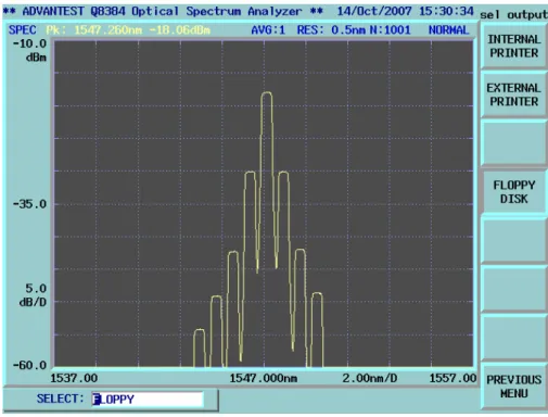
(21) (1547.2nm) was chosen for the measurement, because this channel was almost the center channel, and the performance of this channel should be typical among all channels. The signal wavelengths for the upstream traffic were set identical to the downstream signals, and the BER was measured. The results are shown in figures 3.5. Open circles denote the single channel unidirectional transmission performance, open triangles denote the WDM unidirectional transmission performance, open squares denote the WDM bidirectional transmission performance, and cross symbols denote the WDM bidirectional transmission with Raman amplification performance.. Single channel WDM unidirection WDM bidirection. -4. 10. WDM bidirection with Raman. -5. BER. 10. -6. 10. -7. 10. -8. 10. -9. 10. -35. -30 -25 -20 -15 -10 RX Input Power (dBm). Fig. 3.5 Measured BER with identical up/down wavelengths As shown in figure 3.5, WDM unidirectional transmission case had about 2.5dB penalty compared to the single channel unidirectional transmission. The reason of the penalty could be attributed to the crosstalk from the neighboring channels since the power differences between the detected channel and its neighboring channels were only 12dB after the optical bandpass filter as shown in figure 3.6. This penalty could be reduced if we used a narrower bandwidth optical filter or an AWG. Then, WDM 15.
(22) bidirectional transmission case showed another 1.5dB penalty compared to WDM unidirectional transmission. The reason of the penalty could be attributed to the coherent crosstalk between the downstream signal and the Rayleigh backscattered upstream signal. As the wavelengths of the upstream signals and the downstream signals were set to be the same, the Rayleigh backscattered upstream light caused a coherent interference to the downstream light, and this caused the significant penalty. Furthermore, WDM bidirectional transmission with the Raman amplifier case showed about 2dB additional penalty compared to WDM bidirectional transmission. The reason could be understood that the Rayleigh backscattering was amplified by the Raman amplifier, and the coherent crosstalk was enhanced.. Fig. 3.6 Measured optical spectrum of channel 5 after the optical filter. 3.4 Strategy to eliminate the effect of coherent and incoherent crosstalk For the coherent crosstalk case, the same wavelength of the light sources causes the coherent crosstalk, and it leads to significant penalty. If the wavelengths of the light sources are different, they do not cause the coherent crosstalk. Therefore, the upstream signal wavelengths were shifted by 0.2nm. The BER performance of channel 5 was measured again. The results are shown in figure 3.7. Open circles denote the single channel unidirectional transmission performance, open triangles denote the WDM unidirectional transmission performance, open squares denote the 16.
(23) WDM bidirectional transmission performance, and cross symbols denote the WDM bidirectional transmission with Raman amplification performance. As shown in figure 3.7, WDM bidirectional transmission caused almost no penalty compared to WDM unidirectional transmission when there was 0.2nm wavelength shifting. The reason could be explained that although the upstream light still generated the Rayleigh backscattered light, it was incoherent to the downstream signal and it did not cause any significant penalty. In addition, there was no significant penalty for WDM bidirectional transmission with Raman amplifier. From these results, the wavelength shifting of the upstream traffic was confirmed to be quite effective for the WDM-PON system utilizing the Raman amplifier.. Single channel WDM unidirection WDM bidirection. -4. 10. WDM bidirection with Raman. -5. BER. 10. -6. 10. -7. 10. -8. 10. -9. 10. -35. -30 -25 -20 -15 -10 RX Input Power (dBm). Fig. 3.7 Measured BER with different up/down wavelengths For the incoherent crosstalk case, the penalty was due to the crosstalk from the neighboring channels. Decreasing the power of the neighboring channel could decrease the penalty. Originally, one optical filter with 0.8nm bandwidth was used in the experiment, and two optical filters in cascade would be effective to obtain smaller 17.
(24) penalty. Therefore, two optical filters were used in the following experiments.. 3.5 Conclusion The WDM-PON system with the Raman amplifier was experimentally investigated. The transmission performance was characterized for identical upstream/downstream signal wavelength case and different upstream/downstream signal wavelength case. The Rayleigh backscattering caused the significant penalty for the identical wavelength case, while the penalty was minimized when there was a proper wavelength shifting. As a result, 0.2nm wavelength shifting was quite effective even when the Raman amplifier was adopted.. References [1] J. Prat, M. Omella, and V.Polo, “Wavelength shifting for colorless ONUs in single-fiber WDM-PONs,” Proc. of OFC 2007, paper OTuG6, 2007. [2] H. Taga, W.-T. Shih, J.-Y. Wu, S.-S. Shu, S.-E. Liu, T.-H. Wu, and Y.-J. Chiu, “Experimental demonstration of DWDM passive optical network with colorless ONU incorporating wavelength interleaver,” Submitted to IEICE Trans. Commun. [3] G. Talli and P. D. Townsend, “Feasibility demonstration of 100 km reach DWDM superPON with upstream bit rates of 2.5 Gb/s and 10Gb/s,” Proc. of OFC 2005, paper OFI1, 2005. [4] T. H. Wood, R. A. Linke, B. L. Kasper and E. C. Carr, “Observation of Coherent Rayleigh Noise in Single-Source Bidirectional Optical Fiber Systems,” IEEE J. Lightwave Technol., vol. 6, no.2, pp. 346-352, 1988. [5] J. L. Gimlett, M. Z. Iqbal, N. K. Cheung, A. Righetti, F. Fontana and G. Grasso, "Observation of equivalent Rayleigh scattering mirrors in lightwave systems with optical amplifiers", IEEE Photon. Technol. Lett., vol. 2, pp. 211 -213, 1990. [6] S.-K. Liaw, S.-L. Tzeng and Y.-J. Hung, "Rayleigh backscattering induced power penalty on bidirectional wavelength reuse fiber systems”, Optics Communications, vol.188, no.1, pp. 63-67, 2001. [7] B. K. Min, W. Lee, and N. Park, "Efficient formulation of Raman amplifier propagation equations with average power analysis," IEEE Photon. Technol. Lett., vol. 12, no. 11, pp. 1486-1488, 2000. [8] S. V. Chernikov, S. A. E. Lewis and J. R. Taylor, "Broadband Raman amplifiers in the spectral range of 1480-1620 nm", Proc. of OFC/IOOC'99, paper WG6, 1999. [9] M. G. Raymer and J. G. Mostowsky, “Stimulated Raman scattering: Unified treatment of spontaneous initiation and spatial propagation,” Phys. Rev. vol. 24, no. 4, pp.1980-1993, 1981. [10]G..P.Agrawal. “Fiber-Optic Communication Systems” 3d ed. 18.
(25) Chapter 4 Long reach WDM-PON system using Raman amplifier 4.1 Introduction Current PON system covers a reach of within 20km from a CO, because the market of the access system is focusing on well-populated area. To enhance the applicable area, transmission reach of the PON system must be extended. Long reach PON that can provide the high splitting ratio and the capacity is attractive. A single fiber based bidirectional 80km long reach PON link with symmetric up/downstream data rate of 10 Gb/s using a forward and backward distributed Raman fiber amplification has been demonstrated [1]. Symmetric upstream and downstream data rates of 10 Gb/s, 1024 splitting factor with 100km reach has also been demonstrated [2]. In this chapter, the reach is extended to 84km with distributed Raman Amplifier to realize long reach WDM-PON using a single fiber.. 4.2 Experimental setup Figure 4.1 shows a schematic diagram of the experimental setup similar to previous chapter. The wavelengths of the LDs were changed from 1556.7nm to 1562.3nm with 0.8nm (=100GHz) separation. The signal wavelengths of the upstream traffic were set to be identical to the downstream traffic, or were shifted by 0.2nm, these wavelengths from 1556.9nm to 1562.5nm with 0.8nm channel separation. These wavelengths were modulated simultaneously by a LiNbO3 intensity modulator with 10.66Gbit/s, 215-1 pattern. The transmission line comprised 84km non-zero dispersion shifted fiber (NZDSF) whose loss including the optical connectors was about 19dB. Total chromatic dispersion of the fiber was about 380ps/nm at 1550nm. At both ends, there were two WDM couplers to combine the forward and the backward Raman pump light to the transmission line. Each Raman pump source had two pump wavelengths, and they were 1450nm and 1460nm. The total output power of these two pump lasers was set to 300mW. The total on-off gain of the Raman amplifiers to the signals was about 20.5dB. At both Local Exchange and Service node, there were an EDFA preamplifier and two 0.7nm bandwidth optical bandpass filters in cascade (total 0.4nm bandwidth) in front of the optical receiver.. 19.
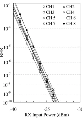
(26) DFB-LD. λ2. DFB-LD. λ3. DFB-LD. λ8. 10.66G 215-1. 100GHz AWG. λ1. λ1' DFB-LD 100GHz AWG. λ3' DFB-LD. Optical Circulator. LiNbO3 Mach-Zehnder modulator 10.66Gb/s RX Service node. DFB-LD. λ2' DFB-LD. 380ps/nm. Local Exchange 10.66G 215-1 Optical Circulator. 10.66Gb/s RX. λ8' DFB-LD. NZDSF 80km. Raman pump LD (300mW). Raman pump LD (300mW). Fig. 4.1 A schematic diagram of the experimental setup. 4.3 Results and discussions The BER performances of 8 channels for both up/downstream signals were measured. Figures 4.2 and 4.3 are the BER performance of up/downstream channels, respectively, with identical up/downstream signal wavelength. Figures 4.4 and 4.5 are the BER performance of up/downstream channels, respectively, with different up/downstream single wavelength. It can be observed from the figures that Rayleigh backscattering caused another 3 dB penalty in the identical up/downstream single wavelengths due to the coherent crosstalk. In addition, the penalty caused by the WDM incoherent crosstalk significantly observed in the previous chapter was reduced by two cascaded optical bandpass filters in front of the optical receiver. As seen from the figures, the WDM incoherent crosstalk penalty of any channel was below 1dB.. 20.
(27) -3. 10. -4. 10. -5. 10. -6. 10. -7. 10. -8. 10. -9. 10. -10. CH1 CH3 CH 5 CH 7. CH2 CH4 CH 6 CH 8. BER. 10. -40. -35 RX Input Power (dBm). -30. Fig. 4.2 Measured BER of all upstream channels with identical up/down wavelength. -3. 10. -4. 10. -5. 10. -6. 10. -7. 10. -8. 10. -9. 10. -10. BER. 10. -40. CH1 CH3 CH 5 CH 7. CH2 CH4 CH 6 CH 8. -35 RX Input Power (dBm). -30. Fig. 4.3 Measured BER of all downstream channels with identical up/dow wavelength. 21.
(28) -3. 10. -4. 10. -5. 10. -6. 10. -7. 10. -8. 10. -9. 10. -10. CH1 CH3 CH 5 CH 7. CH2 CH4 CH 6 CH 8. BER. 10. -40. -35 RX Input Power (dBm). -30. Fig. 4.4 Measured BER of all upstream channels with different up/dow wavelength 10-3. 10. CH1 CH3 CH 5 CH 7. -4. CH2 CH4 CH 6 CH 8. BER. 10-5 10-6 10-7. 10. -8. 10-9 10. -10. -40. -35 RX Input Power (dBm). -30. Fig. 4.5 Measured BER of all downstream channels with different up/down wavelength 22.
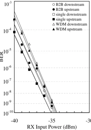
(29) 10-3. B2B downstream B2B upstream single downstream single upstream WDM downstream WDM upstream. 10-4. BER. 10. -5. 10-6 10-7 10-8 10-9 10-10 -40. -35 RX Input Power (dBm). -30. Fig. 4.6 Measured BER of channel 5 with identical up/down wavelength. 10-3. -4. 10. -5. 10. -6. 10. -7. 10. -8. 10. -9. 10. -10. BER. 10. B2B downstream B2B upstream single downstream single upstream WDM downstream WDM upstream. -40. -35 RX Input Power (dBm). -30. Fig. 4.7 Measured BER of channel 5 with different up/down wavelength.. 23.
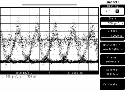
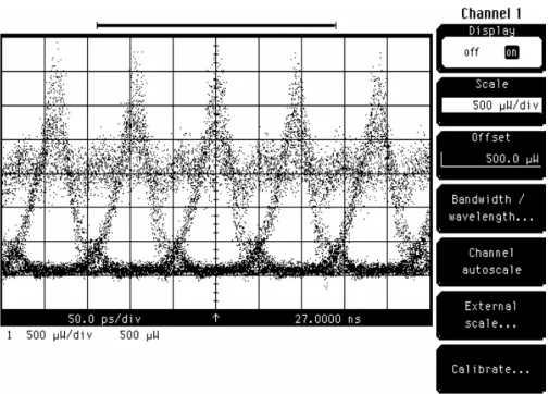
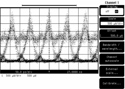
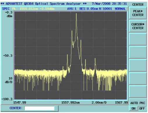
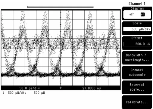
(30) Since the BER performances of all channels were similar, the performance of channel 5 (1559.9nm), that is almost the center channel, is shown in figures 4.6 and 4.7. Figure 4.6 shows the measured BER of identical up/down wavelength for back-to-back, single channel unidirectional and bidirectional WDM, while figure 4.7 shows different wavelength case. The BER performance of single channel unidirectional transmission of up/downstream is better than that of the back-to-back performance because the bias voltage of the intensity modulator was adjusted to generate an initial chirp to compensate the fiber dispersion (also called pre-chirp). 10.66 Gb/s symmetric up/downstream bidirectional 84km long backhaul link supported by Raman amplifier can be implemented with a power penalty of about 0.5 dB. Power budget margin of 23 dB and 19.5 dB can be obtained for both directions in identical up/downstream signal wavelength case and different up/downstream signal wavelength case, respectively. By observing the spectrum of the signal in front of the filter, some information about the performance of the signal, like optical SNR, noise generated during the transmission process, the crosstalk from the other channels, can be obtained. From the eye diagram, the performance can be estimated. They are shown in figures 4.8-39.. 24.
(31) Fig. 4.8 Measured optical spectrum of channel 1 upstream after the optical filter. Fig. 4.9 Measured optical eye of channel 1 upstream after the optical filter. 25.
(32) Fig. 4.10 Measured optical spectrum of channel 2 upstream after the optical filter. Fig. 4.11 Measured optical eye of channel 2 upstream after the optical filter. 26.
(33) Fig. 4.12 Measured optical spectrum of channel 3 upstream after the optical filter. Fig. 4.13 Measured optical eye of channel 3 upstream after the optical filter. 27.
(34) Fig. 4.14 Measured optical spectrum of channel 4 upstream after the optical filter. Fig. 4.15 Measured optical eye of channel 4 upstream after the optical filter. 28.
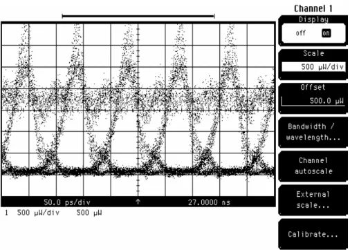
(35) Fig. 4.16 Measured optical spectrum of channel 5 upstream after the optical filter. Fig. 4.17 Measured optical eye of channel 5 upstream after the optical filter. 29.
(36) Fig. 4.18 Measured optical spectrum of channel 6 upstream after the optical filter. Fig. 4.19 Measured optical eye of channel 6 upstream after the optical filter. 30.
(37) Fig. 4.20 Measured optical spectrum of channel 7 upstream after the optical filter. Fig. 4.21 Measured optical eye of channel 7 upstream after the optical filter. 31.
(38) Fig. 4.22 Measured optical spectrum of channel 8 upstream after the optical filter. Fig. 4.23 Measured optical eye of channel 8 upstream after the optical filter. 32.
(39) Fig.4.24 Measured optical spectrum of channel 1 downstream after the optical filter. Fig. 4.25 Measured optical eye of channel 1 downstream after the optical filter. 33.
(40) Fig. 4.26 Measured optical spectrum of channel 2 downstream after the optical filter. Fig. 4.27 Measured optical eye of channel 2 downstream after the optical filter. 34.
(41) Fig. 4.28 Measured optical spectrum of channel 3 downstream after the optical filter. Fig. 4.29 Measured optical eye of channel 3 downstream after the optical filter. 35.
(42) Fig. 4.30 Measured optical spectrum of channel 4 downstream after the optical filter. Fig. 4.31 Measured optical eye of channel 4 downstream after the optical filter. 36.
(43) Fig. 4.32 Measured optical spectrum of channel 5 downstream after the optical filter. Fig. 4.33 Measured optical eye of channel 5 downstream after the optical filter. 37.
(44) Fig. 4.34 Measured optical spectrum of channel 6 downstream after the optical filter. Fig. 4.35 Measured optical eye of channel 6 downstream after the optical filter. 38.
(45) Fig. 4.36 Measured optical spectrum of channel 7 downstream after the optical filter. Fig. 4.37 Measured optical eye of channel 7 downstream after the optical filter. 39.
(46) Fig. 4.38 Measured optical spectrum of channel 8 downstream after the optical filter. Fig. 4.39 Measured optical eye of channel 8 downstream after the optical filter. 40.
(47) 4.4 Conclusion A 10.66 Gb/s symmetric up/downstream bidirectional 84km WDM-PON supported by Raman amplifier using single fiber was successfully demonstrated. By shifting signal wavelengths, power budget margin of 23dB could be achieved. This technology can be applied to integrate the metro network and the access network.. References [1] I. T. Monroy, R. Kjaer, B. Palsdottir, A. M. J. Koonen, and P. Jeppesen, “10 Gb/s bidirectional single fiber long reach PON link with distributed Raman amplification,” Proc. of ECOC 2006, paper We3.P.166. [2] D. P. Shea and J. E. Mitchell, "A 10-Gb/s 1024-Way-Split 100-km Long-Reach Optical-Access Network," IEEE/OSA J. Lightwave Technol, vol. 25, no.3, pp. 685-693, 2007.. 41.
(48) Chapter 5 Summary The PON is replacing the copper cable of the customer network, because it can provide higher bit-rate with lower cost. As the customers rely on the network more and more to support their convenient life style, it is important to realize higher speed and reliable network. The next generation of PON, i.e., WDM-PON, has the ability to provide customers much higher bandwidth and security than other kind of PONs, and it is important to study the issues of the WDM-PON. In this master thesis, two experiments were conducted. In the first experiment, the same wavelength for both upstream traffic and downstream traffic degraded the performance significantly. However, better performance was obtained by shifting the upstream wavelength. The reason was the coherent crosstalk caused by the Rayleigh backscattering. Since the Rayleigh backscattering can be amplified by the Raman amplifier, penalty increase due to the Raman amplifier was also demonstrated in this experiment. In the second experiment, bidirectional pumping of the Raman amplifier and the NZDSF increased the Raman gain effectively, and the reach of the system was extended to 80km. Although Rayleigh backscattering caused another 3 dB crosstalk penalty in the identical up/downstream signal wavelength case, 19.5dB power budget margin could be achieved for the system, and it was extended to 23 dB for different up/downstream single wavelength case. This experiment proved the feasibility of the long reach WDM-PON system supported by the Raman amplifiers for both identical and different up/downstream signal wavelength cases. The system based on this technology can enhance the applicable area of the PON technology, and its sufficient power budget margin can make splitting ratio high enough to support large number of users. The long reach WDM-PON system can be further enhanced by combining the TDM-PON. Such hybrid PON system should be attractive, because it can provide integrated metro and access network. The serving range of such hybrid system can cover 100km distance and (8 channels * 16 splitting =) 128 customers. The achievement of this master thesis can be summarized as follows. (1) A concept of next generation optical fiber access network was proposed. (2) The effect of the Rayleigh backscattering upon the transmission performance of the bidirectional WDM-PON system was evaluated experimentally. The importance of the wavelength assignment was pointed out. 42.
(49) (3) Extended reach of the WDM-PON system was demonstrated using the Raman amplifier. The demonstration showed the feasibility of the proposed hybrid PON system. As these achievements are significant enough to contribute the progress of the optical fiber communication system, the study of this master thesis is completed successfully.. 43.
(50)
數據

+7
相關文件
3) 請先充分地搓 揉預計切除的部 分。這樣使外皮 會與裡面芯線產 生間隙。.. 4) 將網路線夾在剝 皮工具的最外側溝
3) 請先充分地搓 揉預計切除的部 分。這樣使外皮 會與裡面芯線產 生間隙。?. 4) 將網路線夾在剝 皮工具的最外側溝
In case of non UPnP AV scenario, any application (acting as a Control Point) can invoke the QosManager service for setting up the Quality of Service for a particular traffic..
電機工程學系暨研究所( EE ) 光電工程學研究所(GIPO) 電信工程學研究所(GICE) 電子工程學研究所(GIEE) 資訊工程學系暨研究所(CS IE )
172, Zhongzheng Rd., Luzhou Dist., New Taipei City (5F International Conference Room, Teaching Building, National Open University)... 172, Zhongzheng Rd., Luzhou Dist., New
由於較大型網路的 規劃必須考慮到資料傳 輸效率的問題,所以在 規劃時必須將網路切割 成多個子網路,稱為網 際網路。橋接器是最早
在 1855 年英國科學家 Lord Rayleigh 於地震研 究領域就發現了表面聲波的存在,此後則將此現象 運用於地震研究上,此表面波亦被稱為 Rayleigh wave ;直到 1965
Now, nearly all of the current flows through wire S since it has a much lower resistance than the light bulb. The light bulb does not glow because the current flowing through it
