Highly Reliable Liquid-Phase Deposited SiO, with Nitrous Oxide Plasma
Post-Treatment for Low Temperature Processed Poly-Si TFT's
C. F.
Yeh, Darren C. Chen, C. Y. Lu, C. Liu, S.
T. Lee, C. H. Liu and T. J. Chen
Annealing Condition
As-deposited Furnace(6WC 0. lhr)
Department of Electronic Engineering, National Chiao Tung University, Taiwan, R.O.C.
thickness refractive P-etch rate dielectric
(A) index (.&Is) constant
352 1395 2 0 1 3459 354 1396 6 1 3 632 Abstract 0, Plasma 15' 4 5 I 352 1.396 14.2 3.542 Low temperature (-300°C) N,O plasma annealing for liquid- phase deposited (LPD) gate oxide has been proposed for the first time. Physicochemical and electrical characterizations show that the N,O-treated LPD-SiO, improves breakdown field, interface state density, and Si-rich phenomenon. This novel technology has been also successfidly applied to LTP poly-Si TFT's, which reveal excellent characteristics and reliability. It is believed that the N,O plasma post-treatment not only improves the oxide quality, but also passivates the trap states in poly-Si channel.
Introduction
I
N.OPlasma5'I
386 1.419 9.2 3.716I
I
N,OPlasma 15'I
465 1.430 8.3 3.847I
I
0,~1asma 5'I
354 1.396 13.9 3.562I
N,O Plasma 5' 3 5 % 3 0-
v.
e s 2 0-
E 1 5 - 0 5I
x
1.-
* 9 - - f r . ._--
N\
0 100 200 300 400 5 0 0 600 7 W 0 0Sputter Time (sec)
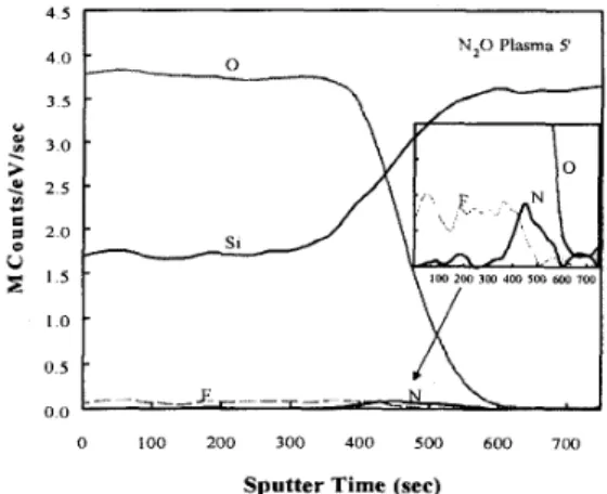
Fig. 1 AES depth profiles for N,O-plasma (5 min) post-treated LPD-SiO,. the N,O plasma post-treatment is important and indispensable for improving TFT performance and reliability.
Experiments
A . Preparation of N,O plasma post-treated LPD-SiO,
The chemical reaction for LPD-SiO, growth can be simply represented by the following equilibrium reaction:
H,SiF, + 2H,O
++
6HF + SiO, AH < 0. (1)The deposition rate of LPD-Si0, is controlled by change of H,O quantity. First, Hydrofluorosilicic acid with saturated SiO, was prepared at 23°C for 17 hours and the Si substrates with native oxide were then immersed into the supersaturated solution at 18"C, where SiO, was deposited on the test samples by adding enough water. Finally, the LPD-SiO, samples were performed N,O plasma treatment for 5-1 5 minutes.
B. Fabrication of LTP Poly-Si TFT's
Low temperature poly-Si TFT's are fabricated with a maximum processing temperature of 600°C. Undoped 1000A-thick poly-Si film and 370A-thick LTP-SiO, was deposited as the active layer and gate insulator, respectively. After deposition of the LPD gate oxide, the N,O plasma was performed for 5-15 minutes to form the SiN,O,-, composition. The top-gate structures with self-aligned implantation were
10.6.1
106 It LPD-SiOdSi interface ,+ IO' 8 s
U"
IO'$
E 103 e 102 00 101 a [II '?Si H 1 8 0 Si+F Si+N 0 10 20 30 40 50 60 70 80 Depth (nm)Fig 2 SIMS depth profiles for as-deposited LPD-SiO,
106 :h-- LPD-Si02ISi interface I H Si+N 1 8 0 Si+F N,O Plasma 5'
t
0 10 20 3 0 40 50 60 70 80 Depth (nm)Fig 3 SIMS depth profiles of LPD-SiO, after N,O plasma post-treatment for 5 minutes
adopted and 5000 A-thick tetraethyl orthosilicate (TEOS) SiO, was deposited as the passivation layer. After contact holes were opened, a 5000 A-thick aluminum layer was evaporated and patterned. Aluminum sintering was performed at 400°C for 30 minutes. The detailed fabrication procedures are described in the earlier report [8].
Results and Discussion
A. Physicochemical Characteristics of LPD-SiNxO,,
Table 1 shows the basic characteristics of LPD-SiO, with 0, and N,O plasma post-treatments. The result of 0, fumace annealing is also shown for comparison. After the N,O plasma post-treatment, both refractive index and dielectric constant increase, which implies that the N,O plasma re- oxidizes LPD-SiO, , and hence improves the oxide structure. The small p-etch rate also indicates the superior densification
of LPD-SiN,O,-, film. Fig. 1 shows the AES depth profiles for the N,O plasma post-treated LPD-SiO,. The N,O plasma improves the Si-rich phenomenon and reduces the fluorine concentration rather than the as-deposited LPD-SiO,. In
0 1 I
- 4 - 3 - 2 - 1 0 1 2 3
Gate Bias (V)
Fig. 4 C-V characteristics of the LPD-SiO, with different post-treatment
conditions.
addition, it is found that nitrogen atoms are piled up at SUSiO, interfaces. The result can be further verified by the SIMS experiments. Fig. 2 and Fig. 3 show the SIMS depth profiles for the as-deposited LPD-Si0, and the LPD-SiN,O,-,, respectively, where the concentration of nitrogen in the as- deposited LPD-SiO, is extremely low, while a pronounced increase of nitrogen concentration in the LPD-SiN,O,., is observed. From the above results, it can be noted that most of the nitrogen atoms in the LPD-SiNxO,-, pile up at the Si/LPD-SiO, interface, and some of them exist in oxide bulk.
B. Electrical Characteristics of LPD-SiN,O,,
Fig. 4 shows the C-V characteristics of LPD-SiO, with different post-treatment conditions, where curves of the LPD- SiN,O,, samples are shifted toward left side as compared with that of the as-deposited and 0, plasma samples. It implies the breaking of Si-OH and Si-F bonds, so OH' and F- ions are diffused out from the LPD-SiO, film. These escaped
-0- As-deposited U Furnace -t N,O Plasma 5' 4 0, Plasma 5'
I
- 0 3 - 0 2 -01 0 0 1 0 2 0 3 Bandgap Energy (eV)Fig 5 Comparisons of interface trap densities for the LPD-SiO, with different post-treatment conditions
10.6.2
negative ions will subsequently leave oxygen vacancies 0,Si Si=03, which can be thought as the positive charges, and therefore results in the left shift of C-V curves. Fig. 5
shows the comparisons of interface trap densities (DIJ for the LPD-SiO, with different post-treatment conditions. The N,O sample has smaller D,, (-10" eV-'cm-') as compared with the as-deposited sample (7x10" eV%m-2). It can be attributed to the excellent improvement of LPD oxide, which is due to the oxygen diffusion as well as the nitrogen incorporation into the WLPD-SiO, interface. The nitrogen incorporation forms a buffered layer, which is composed of Si=N bonds within the first lOA fiom the interface and Si=N-0 bonds outside of the first lOA region [9]. The buffered layer plays an important role in reducing the interface stress, caused by the Si lattice-mismatch between the Si bulk and the oxide overlayer. The lattice-mismatch mainly results from the incomplete bonding of Si+' and W3. The J-E characteristics of the LPD-SiO, with different post-treatment conditions are shown in Fig. 6 . At lower electrical field, the leakage current
-42
-
-43-
-44 -*!
h:::
W -41-
9 -48-
-49-
-50-
5
As-deposited y.I.
a
-
10.4.-
E! 10-5 U Q) L5
0 2 4 6 8 1 0 1 2 Electric Field ( M V l c m )Fig. 6 J-E characteristics of LPD-SiO, with different post-treatments.
0 3 6 9 12 15
E,,,, (MVIcm)
Fig. 7 Weibull plots of breakdown field for LPD-SiO, with different post- treatments. A 4B = 3 36 eV -51 -I \ 0 8 1 1 2 1 4 1 6 1 8 2 IIE (10' c m N )
Fig 8 Fowler-Nordheim plots of LPD-SiO, with different post-treatments
10.3
,
I
-10 -5 0 5 10 1 5 20
Gate Voltage V, (V)
Fig 9 Comparison of transfer characteristics for the LTP poly-Si TFT's with different post-treatment conditions
density for all samples is nearly the same (-2~10.~ Alcm'). However, after the N,O plasma post-treatment for 5 minutes, the electrical breakdown field of the LPD-SiO, is obviously higher (-1 1 .OMV/cm) than that of other samples. In addition, the onset-tunneling field of the N,O sample is also larger than that of others. They can be attributed to that the N,O plasma treatment effectively relieves the interfacial stress and improves the Si-rich phenomenon. The strong Si-N bonds prevent electrons from direct tunneling between Si islands. Fig. 7 shows the Weibull plots of electrical breakdown field for different LPD samples. As described in Fig. 6 , the N20 sample has the largest electrical breakdown field and best breakdown uniformity than other samples. Fig. 8 shows the Fowler-Nordheim plots for different LPD samples, where a linear relationship for all samples is obtained. The barrier height at the SiLPD-SiO, interface is calculated from these linear plots. As shown in Fig. 8, the LPD-SiN,O,-, improves barrier height of the as-deposited LPD-SiO, fiom 1.78 to
3.36eV.
10.6.3
C. Performance and Reliability for LTP poly-Si TFTS
Gateoxide
Post-Annealing Furnace N,OPlasma5’
Fig. 9 shows the transfer characteristics for the LTP poly-Si TFT’s with different post-treated LPD gate oxide. It is clear that the N,O sample much improves the electrical characteristics such as driving current, off-state current, subthreshold slope and threshold voltage rather than the furnace annealing and 0, plasma samples. The calculated device parameters of all samples are summarized in Table 2.
For the N 2 0 plasma sample (5 min), pFE increased from 7.71
to 16.31 cm’Nsec and V, decreased from 11.89 to 7.14 V. The superior device characteristics suggest that the N 2 0 sample has lower trap-state density and grain barrier height in the poly-Si channel. Fig. 10 shows the ON-current degradations as a fimction of stress time for different TFT samples under the stress of VGS=VDs=15V. The degradation of the N,O sample is smaller than that of other samples. As it was known that the degradation of such an on-state stress is mainly due to the breaking of weak Si-Si and Si-H bonds, which generally forms the metastable trap states. The N,O plasma treatment can effectively passivate trap states and replace these weak Si-Si bonds with the strong Si-N bonds. Fig. 11 shows the ON-current degradation as a function of stress time for different TFT samples under the stress of V,,=OV and VGS=2OV. The N,O sample reveals much better stress endurance than other samples. It implies that the N20 sample can prevent electrons from trapping in the gate oxide. From the above results, the excellent gate-oxide reliability in N,O sample can be thought as the incorporation of nitrogen atoms at the LPD-SiO,/poly-Si interface, which forms strong Si-N bonds and hence relieves the interfacial stress.
V,, Swing L, L., P F ~ N, (V) (V/dec) (PA) (PA) “”“ (cm’N sec) (Cm *) 1189 1708 3 7 0 6 4 5 7 0 8 11x10’ 7 7 1 129x10” 7 1 4 1250 1946 5905 330x10” 1631 7 5 5 ~ l O ’ ~ Conclusion
s
v E - 0 5 - 0 2 I.
0 - 1 0 - H Q 0 * 01 - 1 5 - p: 5=
- 2 0 - 0 .L - 2 5 - L ay
- 3 0 - ;4In conclusion, a highly reliable LPD-SiN,O,-,, deposition of LPD-SiO, followed by N,O plasma treatment, has been developed for low temperature and high quality gate oxide. From the analysis of physico-chemical and electrical properties, the LPD-SiN,O,, reveals improved oxide quality and interface characteristics such as dielectric constant, Si- rich phenomenon and interface trap density. As applied to LTP poly-Si TFT’s, the device performance and reliability of the LPD-SiN,O,-x TFT are better than the furnace annealing and 0, plasma TFT’s. 0 -
-
-5 - hs
8
-$.,
-10-
I2
-20: m2
-15-
c, 5 Jz m -25 - E-
E
-30-
32
-35-
0Acknowledgements The authors would like to acknowledge the financial support by the National Science Council, Taiwan, R.O.C., under contract NSC87-2215-1009-048.
References 1) C. F. Yeh et al., J. Electrochem. Soc., p.3177, 1994.
2) C. F. Yeh et al., J. Electrochem. Soc., p.3579, 1995. 3) C. F. Yeh et al., Appl. Phys. Lett., p.938, 1995.
4) C. F. Yeh et al., J. Electrochem. Soc., p.3645, 1997.
5) C. E Yeh et al., J. Electrochem. Soc., p.252, 1998.
6) P. C. Chen et al., Jpn. J. Appl. Phys., p.973, 1995.
7) R. I. Hegde et al., Appl. Phys. Lett., p.2882, 1995.
8) C. F. Yeh et al., IEEE EDL, EDL-11, p.473, 1995. 9) S. R. Kaluri et al., J. Electrochem. Soc., p.662, 1998.
Table 2 Calculated device parameters for the LTP poly-Si TFT’s with different post-treatment conditions.
IN,OPlasma15’1 7 5 7 1398 132.1 1138 l.I6xlO* 13.92 6.62xIO”l
I
O,Plasma5’1
8 9 4 1304 1465 9 9 8 5 1 4 6 ~ 1 0 ~ 1455 8 0 1 x 1 0 ” )I
O,Plasma15’I
8 9 3 1 2 8 5 1484 5610 265xIO* 1480 8IOxlO’’l0 WiL = 20pmI5~un Stress @ VDs = V,, = 15V -0- Furnace t N , O Plasma 5’ -3-0, Plasma 5’ +02 Plasma 15’ -3.5
1
10’ 102 10’ I o4 IO*Stress Time (sec)
Fig. 10 ON-current degradation with stress time for the LTP poly-Si TFT’s with different post-treatment conditions under the stress of V,,=VDs=l5V.
W/L = 20run/5p Stress @ V, = 20V -0- Furnace t N , O Plasma 5’ v,, = ov -CY- 0, Plasma 5’ -31i 0, Plasma 15’ 10’ 102 103 1 0 4 10s
Stress Time (sec)
Fig, 1 1 ON-current degradation with stress time for the LTP poly-Si TFT’s with different post-treatment conditions under the stress o f V,,=OV,
v,,=20v.