Discrete Multitone Modulation With Principal
Component Filter Banks
P. P. Vaidyanathan, Fellow, IEEE, Yuan-Pei Lin, Member, IEEE, Sony Akkarakaran, Member, IEEE, and
See-May Phoong, Associate Member, IEEE
Abstract—Discrete multitone (DMT) modulation is an attractive
method for communication over a nonflat channel with possibly colored noise. The uniform discrete Fourier transforn (DFT) filter bank and cosine modulated filter bank have in the past been used in this system because of low complexity. We show in this paper that principal component filter banks (PCFB) which are known to be optimal for data compression and denoising applications, are also optimal for a number of criteria in DMT modulation communica-tion. For example, the PCFB of the effective channel noise power spectrum (noise psd weighted by the inverse of the channel gain) is optimal for DMT modulation in the sense of maximizing bit rate for fixed power and error probabilities. We also establish an opti-mality property of the PCFB when scalar prefilters and postfilters are used around the channel. The difference between the PCFB and a traditional filter bank such as the brickwall filter bank or DFT filter bank is significant for effective power spectra which depart considerably from monotonicity. The twisted pair channel with its bridged taps, next and fext noises, and AM interference, therefore appears to be a good candidate for the application of a PCFB. This will be demonstrated with the help of numerical results for the case of the ADSL channel.
Index Terms—Channel capacity, digital subscriber loops (DSL),
discrete multitone (DMT) modulation , frequency division multi-plexing (FDM), principal component filter banks (PCFB).
I. INTRODUCTION
D
ISCRETE multitone (DMT) modulation for nonflat chan-nels has been studied by a number of authors in the last decade. The theoretical advantages of multitone modulation were demonstrated in the pioneering paper by Kalet [15] more than ten years ago. DMT has been considered seriously for use in digital subscriber loops (DSL), and excellent descriptions of this can be found in [10] and [31], The DMT system can be regarded as a filter bank in transmultiplexer configuration [1], [36], [41]. Typically, the filter banks used for this purpose areManuscript received December 11, 2001; revised April 3, 2002. This work was supported in part by the National Science Foundation under Grant MIP-0703755, in part by the Office of Naval Research under Grant N00014-99-1-1002, in part by Microsoft Research, Redmond, WA, and in part by the National Science Council (NSC), Taiwan, R.O.C., under Grant 89-2213-E-009-118 and Grant 89-2213-E-002-122. This paper was recommended by Associate Editor W.-S. Lu.
P. P. Vaidyanathan and S. Akkarakaran are with the Department of Electrical Engineering, California Institute of Technology, Pasadena, CA 91125 USA (e-mail: [email protected]).
Y.-P. Lin is with the Department of Electrical and Control Engineering, Na-tional Chiao Tung University, Hsinchu, Taiwan, R.O.C.
S.-M. Phoong is with the Department of Electrical Engineering and Graduate Institute of Communication Engineering, National Taiwan University, Taipei, Taiwan, R.O.C.
Digital Object Identifier 10.1109/TCSI.2002.803249.
DFT filter banks which can be implemented efficiently with the FFT. The filters in these DFT filter banks provide poor separation between adjacent subchannels [27]. It is known that the use of better filters improves performance (e.g., higher bit rate for fixed error probabilities and power). This was clearly demonstrated in [27] using cosine modulated filter banks (CMFB) with sharp filters. Advantages of more general filter banks for this application are also described in [9]. In this paper, we consider a special type of orthonormal filter banks called the principal component filter bank (PCFB) (reviewed in Section IV) and show that it is optimal for the DMT application in a well-defined theoretical sense.
The filter responses in the PCFB depend on the channel transfer function and the noise power spectrum. Moreover even though PCFBs can be defined for infinite filter orders, they are evidently unrealizable. However, there appear to be two reasons why the optimality of the PCFB is of interest. First, it serves as a benchmark for comparing the performance of conventional unoptimized DMT systems which use the DFT, CMFB, and so forth. Second, in applications where the channel characteristics are fixed (e.g., twisted pair lines with standard next and fext noise) we can design the PCFB apriori and approximate it with practical digital filters. Such approximations can yield better performance than unoptimized designs like the DFT at the expense of higher complexity of implementation.
A. Outline and Relation to Past Work
The PCFB was introduced first in [32] and its optimality for a variety of problems was suggested in [35]. It has since been proved to be optimal for a general class of objective functions in signal processing [4], [24], [37], [46]. The role of a specific class of PCFBs in the optimality of DMT systems was first ob-served in [22]. A related problem, namely the optimization of filter bank precoders [13], [44] has been considered in great depth in a series of recent papers by Giannakis and his group [13], [28], [29]. The precoder typically introduces redundancy (like a non maximally decimated filter bank) to combat inter-symbol interference. The precoder and receiver filters can be optimized according to several possible criteria. In this context, an excellent unification of several filter-bank based communi-cation systems (including DMT) can be found in [28]. In this paper, we consider the specific role of the PCFB in the design of optimal orthonormal DMT systems. We believe this provides a fundamentally different viewpoint.
Two other excellent papers on related optimizations should be mentioned here. In [7], the authors consider many fundamental 1057-7122/02$17.00 © 2002 IEEE
variance can be realized by filter design. Next, a very general problem of filter bank optimization is handled in [30] where the authors optimize mutual information by optimizing the transmit and receive filters. Both zero forcing equalizers and minimum mean square equalizers come out of this elegant approach as special cases. In our paper, we consider the case of orthogonal filter banks with the perfect reconstruction property and assume that the channel is equalized by a zero forcing equalizer. Fur-thermore, we do not consider the mutual information but in-stead consider the optimization of useful quantities such as, for example, the actual bit rate with fixed error probabilities and transmitted power. This makes the problem much simpler and leads to very elegant insights. For example, it becomes clear that PCFBs optimize the bit rate for a fixed set of error probabili-ties and power. There is some commonality between the theme of our paper and the results in [30] and [7]. We shall see how-ever, that the approach here is simpler and insightful because we focus directly on the PCFB solution based on simple convexity arguments.
In Section II, we describe the DMT system using multirate filter bank language and formulate a noise model. The bene-fits of optimizing the transmitting filters is motivated with a simple example in Section III. A brief review of PCFBs and their optimality is given in Section IV. More details on this sec-tion can be found in [4], [5]. Various criteria for the optimiza-tion of orthonormal DMT filter banks are presented in Secoptimiza-tion V and solutions presented. The role of principal component filter banks for asymmetric DSL (ADSL) service on twisted pairs is explained in Section VI, along with some numerical examples. Prefiltered orthonormal DMT systems (which are biorthogonal rather than orthonormal) are considered in Section VII and it is shown again that the PCFB has a role in optimality. Some parts of this paper have appeared in [38] and [39].
B. DSP and Multirate Notations
Bold faced letters denote matrices and vectors. The trans-pose, conjugate, and transpose–conjugate of a matrix are de-noted, respectively, as , and . We use a subscript [e.g., , etc.] to distinguish continuous-time quanti-ties from discretized versions. In general, the filters are allowed to be ideal (e.g., brickwall lowpass, etc.). So the transforms may not exist in any region of the plane. The notation should be regarded as an abbreviation for the Fourier trans-form . The language of multirate signal processing [36] will be used extensively throughout this paper. A summary of the most common ones follows.
1) The building block in the figures denotes a decimator
with input/output relation . The building block
denotes an expander with input/output relation
multiple of otherwise.
by . It can be shown that the Fourier transform
of is a superposition of and shifted
versions [36]
2) Some standard abbreviations: a) PCFB: principal com-ponent filter bank, b) DMT: discrete multitone modulation, c) DSL: digital subscriber loop, d) ADSL: asymmetric DSL, e) PR: perfect reconstruction, f) KLT: Karhunen Loeve Transform, g) psd: power spectral density or power spectrum.
II. DMT FILTERBANK
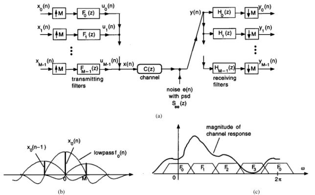
Fig. 1(a) shows the essentials of DMT communication as re-quired for the discussions of this paper. The signals are -bit symbols obtained from a PAM or QAM constellation (Appendix A). These symbols are interpolated -fold by the filters to obtain the subchannel or subband signals . The th transmitting filter has output
(1)
Fig. 1(b) demonstrates how this construction is done for the 0th filter , assumed to be lowpass. Essentially, we draw one copy of the impulse response sequence around every sample of (separated by ) and add them up. The outputs of the filters and so forth, are more complicated waveforms because they are bandpass. The filters
traditionally cover different uniform regions of frequency as shown in Fig. 1(c). The signals are analogous to mod-ulated versions of the “baseband” sequence because the bandwidth is shifted to the passband of . These are packed into adjacent frequency bands (passbands of the filters) and added to obtain the composite signal . Thus
(2)
This signal is then sent through the channel which is represented by a transfer function and additive Gaussian noise
with power spectrum . The received signal is a
distorted and noisy version of . The receiving filter bank separates this signal into the components which are distorted and noisy versions of the symbols . The task at this point is to detect the value of from with acceptable error probability.
In actual practice, the channel is a continuous-time system preceded by conversion and followed by con-version. We have replaced this with discrete equivalents and . The original motivation behind multitone modulation [15] is that the power and/or bits could be allocated in an effi-cient manner in the subchannels, depending on the channel gain
(a)
(b) (c)
Fig. 1. (a) The DMT communication system. (b) The interpolation or modulation performed by the transmitting filterF (z). (c) An example of responses of the transmitting filters.
, and noise psd in that subchannel. In this way, the classical water filling idea for resource allocation [11], [26] could be approximated. For a given transmitted power and probability of error, this yields a better bit rate than direct single tone modulation (assuming no channel coding). The DMT idea is similar in principle to subband coding where a signal to be quantized is first decomposed into subbands. Background material on the DMT system and more generally on the use of digital filter banks in communications can be found in [1], [10], [15], [17], [20], [33].
A. Perfect Reconstruction
In absence of the channel noise , the DMT system of Fig. 1(a) is LTI, with the transfer function from to given by
In general, the symbol is therefore affected by when , resulting in interband interference. For the case
, if the quantity is not a constant, then is affected by when , and we have intraband interfer-ence. The condition to eliminate these two interferences is
(3) If interband and intraband interferences are eliminated, the DMT system is said to be free from intersymbol interference (ISI). We then have the perfect reconstruction or PR property for all (in absence of noise). If the filter responses in Fig. 1(b) are nonoverlapping, then the subchannels are completely isolated. There is no interband ISI, though we
might still have intraband ISI. Even if the filters have overlap as in any practical implementation, we can still avoid both types of ISI as long as (3) holds. In fact, the most popular DMT system uses a DFT filter bank where the filters have significant overlap even though (3) holds.
Biorthogonality: The filter bank is said to be biorthogonal if
(4) This means that the impulse response of the product
filter has the Nyquist( ) or zero-crossing
prop-erty
for and . Under this biorthogonality
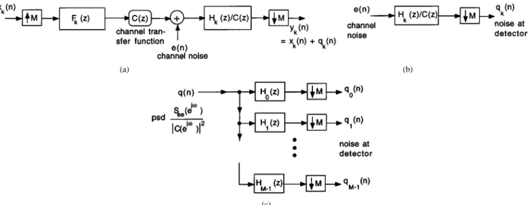
condition, we have perfect reconstruction only if . In this paper, we shall make the simplifying assumption that is biorthogonal and that the channel transfer function is equalized by using the inverse filter or zero-forcing equalizer just before entering the bank
of filters . The path from to now has
the effective form shown in Fig. 2(a).1 In actual practice,
there are many ways to approximate this equalized system (see [25] and references therein). One approach would be to use a time domain equalizer in cascade with the channel and reduce the effective channel to be FIR with a short impulse response. This effective FIR filter is then compensated for by the use of a cyclic prefix followed by appropriate multipliers at the outputs of , called frequency domain equalizers.
1We make the assumption thatC(e ) 6= 0 for any !. Otherwise, we have
(a) (b)
(c)
Fig. 2. (a) The path fromx (n) to y (n) in a DMT system with ideal equalizer 1=C(z). (b) Noise processing in the kth subchannel. (c) Complete noise model. This is explained at length in [10] for DFT based DMT, and a
modification for general DMT has been advanced in [22].
B. Channel Noise Model
Now consider the effect of channel noise . Assuming that is biorthogonal and that is inserted as shown in Fig. 2(a), the th received symbol at time is given by
(5) where is the channel noise filtered through
and decimated [Fig. 2(b)]. If the channel noise is wide sense sta-tionary with power spectrum then, the variance of is
(6) Notice that the noise at the detector input can be viewed as the output of a maximally decimated analysis bank in response to an effective noise source with effective noise psd
(7) This yields the noise model shown in Fig. 2(c).
Optimization of the DMT Filter Bank: We see that there is
some control on the variances of , because we can choose the filters . We can take advantage of this. Even if we assume that the filters are allowed to be ideal, it turns out that the brickwall filter stacking shown in Fig. 1(c) is not necessarily the best choice (Section III). For any given channel, we can de-fine a filter bank called the principal component filter bank. The frequency partitioning generated by such a filter bank is optimal for the channel (Section V).
C. Probability of Error, Transmitted Power, and Bit Rate
For simplicity, we assume that are PAM symbols (Ap-pendix A). Assuming that is a random variable with
equiprobable levels, its variance represents the average power in the symbol . The Gaussian channel noise is
fil-tered through and decimated by . For the
pur-pose of variance calculation, the model for the noise at the detector input can therefore be taken as in Fig. 2(c). Let be the variance of . Then, the probability of error in de-tecting the symbol is given by [26]
(8)
where (area of the normalized
Gaussian tail). Since the -function can be inverted for any non-negative argument, we can invert (8) to obtain
(9) where the exact nature of the function is not of immediate interest. This expression says that if the probability of error has to be or less at the bit rate , then the power in has to be at least as large as . The required total transmitted power is therefore
(10)
Suppose is converted into a continuous time signal by the D/A converter at sampling rate so that
. If a voltage waveform V is applied across a 1-resistor, the power delivered is actually W, regardless of the sample spacing . The samples of are separated by s. With representing the number of bits per sample in , the th subchannel therefore carries bits/s. The total bit rate is therefore
bits/s
(a)
(b)
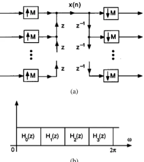
Fig. 3. Examples of orthonormal filter banks. (a) Delay chain system. (b) Brickwall filter bank with contiguous stacking(M = 4).
D. Orthonormal DMT Systems
The set of filters is said to be orthonormal if (11) In an orthonormal DMT system we choose the transmit filters
to be , i.e., . This
en-sures biorthogonality (4), and furthermore the filters
sat-isfy . In terms of impulse
responses, this orthonormality condition is equivalent to
Thus, the composite signal in (2) can be regarded as a superposition of elements from an orthonormal set. In fact, any subchannel signal is a superposition of elements from the
orthonormal set as seen from (1). Fig. 3 shows
two extreme examples of orthonormal filter banks. The first one
is the delay chain system [ and ] and
the second is the ideal brickwall filter bank.
For , (11) yields . If the impulse
response of is denoted as then the preceding
condition is equivalent to the Nyquist( ) or zero-crossing
constraint . Similarly, for biorthogonal filter
banks, the product is Nyquist( ). Orthonormal
filter banks have been thoroughly studied [36], [42]. Here are some of their properties: 1)
(unit energy property); 2) (boundedness);
3) (power complementarity). Stated
here for , these also hold for .
E. Polyphase Representation of DMT Systems
Using the polyphase notations described, for example, in [36, Ch. 5], we can express the row vector of transmitting filters and the column vector of receiving filters as
where is the delay chain vector defined by
. The DMT system can therefore be redrawn as in Fig. 4(a). Using Noble identities [36] the decimator and expander can be moved as shown in Fig. 4(b). This is the polyphase representation of the DMT filter bank. Note that the noise model shown in Fig. 2(c) can be redrawn in polyphase form as shown in Fig. 4(c). This will be quite insightful as we shall see.
The biorthogonality property (4) can be shown to be
equiv-alent to . The special case where the matrix
is unitary for all corresponds to orthonormal DMT
systems. In this case, we choose (transpose
conjugate) for perfect reconstruction. The DMT systems where is a constant unitary matrix has been of some practical importance. In this case, the filters are FIR with lengths . This is the DMT counter part of the transform coder in subband coding theory. The example where is the DFT ma-trix falls under this class.
III. OPTIMALCHOICE OFDMT FILTERBANK
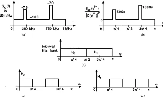
To motivate the usefulness of optimizing the transmitter and receiver filters, consider Fig. 5(a). This shows an example of the effective noise psd in terms of the continuous-time fre-quency variable . [The discretized version of this is
defined in (7)]. This is assumed bandlimited to 1 MHz. The units for are in milliwatts per hertz, and a decibel plot would
show in dB m/Hz as in the figure. Using a
sam-pling rate of 2 MHz, the digital version of
the psd is as shown in Fig. 5(b) where (due
to the factor in the Fourier transform after sampling). These are not unrealistic numbers for typical twisted pair telephone channels for which DMT modulation is the standard. The two bumps (each assumed 10-kHz wide) can be regarded as over-simplified versions of the effects of bridged taps (first bump) and AM noise (second bump) [31]. The rapid decay of channel gain is not depicted in this “toy” example, but we shall do that in Section VI. Consider a two-band DMT system ( ). One choice of the orthonormal filter bank, namely the brickwall stacking, is shown in Fig. 5(c). With the effective psd
as in Fig. 5(b) we can now calculate the variances . Let us pick some values for the remaining parameters.
1) Error probabilities .
2) and . These are the bits in the PAM
con-stellations for and . It makes sense to use smaller value for because there is more noise in the region covered by . Since the average of s is 4, the average bit rate for the 2-MHz sampling rate is 8 Mbits/s.
The average power needed to meet these requirements can be calculated from (10), and the result turns out to be 56 mW. Instead of using the brickwall filter bank suppose we use the filter bank shown in Fig. 5(d) and (e). We still have two sub-bands ( ) but each filter now has two passband regions. It can be verified that this filter bank still satisfies orthonormality (11). We can recalculate the variances now and compute the average power. The result is 5.67 mW. Thus
(a)
(b)
(c)
Fig. 4. (a) Polyphase representation of the DMT filter bank. (b) Simplification using multirate identities. (c) Noise model in polyphase form.
(a) (b)
(c)
(d) (e)
Fig. 5. Demonstrating the effectiveness of good choice of filter banks in the DMT system. (a) Effective noise psd. (b) Digitized version. (c) Traditional brickwall filter bank forM = 2. (d) and (e) Different choice of filter bank.
or about 10 dB. In summary, the modified filter bank achieves the bit rate of 8 Mbits/s and error probability of 10 using almost 10 dB less power!
The difference between the two filter banks in the example is that the variances (whose sum is fixed by orthonormality) are distributed differently depending on the shape of the
effec-tive noise psd . The natural question then is: given an effective noise psd and an arbitrary , how do we choose the orthonormal filter bank to minimize the transmitted power for fixed specifications? The answer is that
should be chosen as a principal component filter bank for the effective noise psd.
IV. PRINCIPALCOMPONENTFILTERBANKS
To define a PCFB first consider two sets of nonnegative
numbers and . We say that majorizes if,
after reordering such that and , we have
for , with equality for . Thus,
all the partial sums in dominate those in . Consider a given class of -band uniform orthonormal filter banks. This class can be the class of transform coders (with filter lengths ), or the class of ideal filter banks (filters allowed to have infinite order, like brickwall filters). Or it could be a prac-tically attractive class like the FIR class with filter orders bounded by a fixed integer, or the so-called cosine modulated class [36]. Given such a class and an input power
spec-trum we say that a filter bank in is a principal
component filter bank or PCFB if the set of its subband variances [i.e., variances of the signals in Fig. 2(c)] majorizes the set of subband variances of all other filter
banks in the class. That is, with and ,
and so forth. The equality follows
au-tomatically from orthonormality.
The advantage of PCFBs is that they are optimal for several problems. This includes subband coding with arbitrary (not nec-essarily high) bit rates, the denoising problem, and so forth, as elaborated in [4]. These arise from the result (proved in [4]) that any concave function of the subband variance vector
is minimized by a PCFB when one exists. Similarly any convex function is maximized by a PCFB. Note that any permutation of the filters in a PCFB retains the PCFB property. Thus, given a particular (concave or convex) objective, we have to choose the right permutation so that the objective is optimized.
Using the preceding results we show in this paper, that PCFBs also serve as optimal solutions to certain problems in commu-nication systems which use DMT modulation. It is possible that PCFBs do not exist for certain classes (e.g., see [4]). But when they exist, they have the stated optimality. Whenever we say that the PCFB is optimal for a problem, the implicit assumption is that the class of filter banks searched is such that a PCFB exists.
A. Construction of the PCFB, and Compaction Filters
For the transform coder class the filters have length . This means that the polyphase matrix in Fig. 4(c) is a
con-stant matrix . Suppose denotes the
autocorre-lation matrix of its input vector. If is chosen as the unitary matrix diagonalizing then, it defines the PCFB in this case. This is nothing but the Karhunen–Loeve transform (KLT) of the effective noise input . This choice decorrelates the sig-nals for each . That is, the autocorrelation matrix of the vector
(12) is diagonalized. For the ideal filter bank class , the ma-trix could have infinite order in . This means in par-ticular that ideal filters are allowed. In this case, the PCFB is such that the power spectrum of the vector (12) is di-agonalized which in particular means that the autocorrelation matrix is diagonal as well. In short, the KLT forces the
instan-taneous decorrelation property for each
, whereas the PCFB for forces the total decorrelation
property for all (with ). In
addition, the PCFB for also induces the spectral
ma-jorization property. That is, assuming are in decreasing order, the power spectra of are ordered such that pointwise for all . It has been shown in [37] that total decorrelation and spectral majorization are neces-sary and sufficient for the PCFB property in the class . For classes other than and the transform coder class, such con-ditions for the PCFB property have not been established. In fact, the existence of a PCFB is not guaranteed for arbitrary classes of orthonormal filter banks (see [4] for counterexample). When a PCFB does exist, there is a sequential algorithm that can be used to construct the filters [23], [4], [5].
Closely associated with PCFBs is the notion of an optimal
compaction filter for a signal with power spec-trum . Such a filter has the property that its output in response to the input has maximum variance subject to the
Nyquist( ) constraint . For the transform
coder class, this filter can be constructed by making the KLT, and taking the receiver filter with largest variance as the solution. For the class the optimal compaction filter can be constructed graphically [37]. Typically, there are multiple pass-bands. For example, the power spectrum in Fig. 6(a) has optimal compaction filter for shown in Fig. 6(b). To construct such a filter we proceed as follows: take any frequency in
and consider the set of frequencies (13) Choose one frequency in this set such that is a max-imum in this set (if there are multiple maxima choose one arbi-trarily). Include this frequency in the passband of , and the remaining frequencies in the stopband. Repeat this
for all in . Set the passband height equal
to and stopband height equal to zero. This completely de-termines the optimal compaction filter for the power
spectrum .
The PCFB can be constructed by designing the filters sequentially one at a time as follows [37]. First, design as an optimal compaction filter for . Then, define a partial power spectrum by removing or
(a) (b)
(c) (d)
(e) (f)
Fig. 6. (a) A power spectrum. (b) Optimum compaction filter forM = 4 for (a). (c) Partial power spectrum obtained by peeling. (d) PCFB for M = 4. (e) A monotone power spectrum. (f) PCFB forM = 4 for (e).
peeling off from those parts that fall in the passbands of [Fig. 6(c)]. Design an optimal compaction filter for this partial psd. Remove those parts of this partial psd that fall under the passband of , and continue this until all the filters have been designed. Fig. 6(d) shows the filters designed in this manner for .
Filter banks constructed using this procedure have the fol-lowing properties.
1) A filter may have more than one passband, but the sum of all its passband widths is equal to , and the heights of the passbands are equal to (e.g., two in Fig. 6).
2) The passbands of any two filters are disjoint, and the filters together cover the entire frequency range.
3) For any consider the set of frequencies in (13). Given any filter , exactly one of these frequencies be-longs to its passband, and the others belong to the stop-band. This property implies two things: a) Each filter is an aliasfree( ) filter. In other words, its output can be deci-mated by without causing overlaps of the copies of the spectrum created by downsampling; b) The decimated
ver-sion for all .
It readily follows from these that the resulting filter bank is orthonormal. The proof that this is actually a PCFB can be found in [37]. For the case of a monotone decreasing power spectrum the compaction filter is lowpass, as demonstrated in Fig. 6(e) and (f). In this case, the PCFB happens to be the tradi-tional brickwall stacking of bandpass filters as shown.
V. OPTIMIZATION OF THEDMT FILTERBANK
In this section, we show how to optimize the orthonormal filter bank used in a DMT system. We assume that the number of subchannels is fixed. The channel transfer function and the noise power spectrum are assumed to be fixed and known as well. A brief overview of these results will also appear in [40].
A. Minimizing Transmitted Power
Recall that the total transmitted power can be expressed in terms of the error probability and noise variances as shown in (10)
Let us assume that the bit rates and probabilities of error are fixed. For this desired combination of and , the total power required depends on the distribution of noise variances . These in turn depend upon the filters . From (9) it follows that the required power in the th band is a linear (hence concave) function2 of . The total
transmitted power is therefore a concave function of the noise variance vector
(14) From Fig. 2(c), we see that this is the vector of subband vari-ances of the orthonormal filter bank in response to
the power spectrum . Recalling the
discus-sion on PCFBs from Section IV we now see that the orthonormal filter bank which minimizes total power for fixed error probabilities and bit rates is indeed a PCFB for the effec-tive noise power spectrum
Having identified this PCFB, the variances are readily computed, from which the powers for fixed bit rate and error probability can be found [using (9)]. The minimized power can then be calculated.
2A linear function is also convex, so there is a permutation of the optimal
PCFB which maximizes rather than minimizes power. Evidently it should be avoided!
B. Maximizing Total Bit Rate
Returning to the error probability expression (8) let us now invert it to obtain a formula for the bit rate . This is tricky because of the way occurs in two places. The factor
however is a weak function of in the sense that it varies from 0.5 to 1 as changes from one to infinity. Suppose we replace
with unity. Then, (8) yields
(15)
so the total is approximately
(16)
This is the achievable without channel coding, for a given set of error probabilities and signal to noise ratios
. Since is convex in (for ),
the total bit rate is convex in the variance vector (14). Thus, the
orthonormal filter bank which maximizes the bit
rate for fixed error probabilities and powers is again a PCFB
for the effective noise psd as before. This
is intuitively appealing since the maximization of bit rate and minimization of total power are consistent goals.
Without the approximation the closed form
expression (16) is not possible, but the convexity of can still be proved in a more elaborate way as shown in Appendix B.
C. Optimal Power Allocation
The preceding result is true regardless of how the total power is allocated among the bands. In particular we can perform optimum power allocation. We have
(17)
where . The optimization of
for fixed total power is a standard problem
in information theory [11]. The solution is given by if this is nonnegative,
otherwise (18)
where is chosen to meet the power constraint. This is the familiar water pouring rule [11] demonstrated in Fig. 7. This power allocation is optimal regardless of the exact choice of the
filter bank . In particular, if is chosen as the
optimal PCFB and then power is allocated as above, it provides the maximum possible DMT bit rate for fixed total power and fixed set of error probabilities. Note that the power allocation automatically determines bit allocation because of the formula (15).
D. Capacity
We observe some similarities and differences between the ac-tual bit rate (16) and the theoretical capacity of the DMT system.
Fig. 7. Optimal power allocation by water pouring.
The biorthogonal DMT system with ideal channel equalizer can be represented by
(19)
where are the modulation symbols and the noise
components shown in Fig. 2(c). In general it is not true that the effective noise components are Gaussian, white, and uncorrelated. However, if the number of bands is large, and the filters are good approximations to ideal filters, then this is nearly the case. In this case, the channel (19) is identical to the parallel Gaussian channel and has information theoretic capacity [11]
(20)
Since the noise variances depend on the filters , the above capacity also depends on them. For the case where is an orthonormal filter bank this capacity is maximized if is chosen as a PCFB for the effective noise psd . The reason again is that (20) is convex in the variance vector (14). Moreover, as in [11], we can optimally
allocate the powers under a power constraint .
Equation (16) is the bit rate achieved for fixed probabili-ties of error , and without channel-coding in subbands. Equation (20) is the information capacity, that is, the theoret-ical upper bound on achievable bit rate with arbitrarily small error. We see that both (16) and (20) depend on the choice of filter bank, and are maximized by the PCFB. Suppose the error
probabilities are for all . A calculation of the
factor shows that if the two quantities and
have to be equal then the total power in (16) should be 9.74 dB more than the power used in (20). Channel coding is included in many DMT systems in order to reduce this gap.3
The preceding discussion on capacity should be interpreted carefully. Indeed, the capacity of a channel is a property of the channel itself, and cannot depend on the filter bank. It depends on the power, the channel transfer function, and the noise. How-ever, in the preceding interpretation we imagine that the -band transmitter filter bank and receiver filter bank are part of the
channel. The number of bands and the powers are
fixed, and the filter bank is assumed orthonormal. Under this condition, (20) represents the capacity of the channel, and it de-pends only on the noise variance distribution which can be controlled by the receiver filters (the transmitter filters are
3This gap is very similar to the gap between PCM rate and channel capacity
(a) (b)
(c) (d)
(e)
Fig. 8. Qualitative frequency-domain plots for ADSL service on the copper twisted-pair channel. (a) and (b) Transmitted psd masks; (c) Channel gainjC (f)j . (d) Various noise spectra. (e) Model for the bridged tap.
conjugates of the receiver filters by orthonormality and perfect reconstruction requirement). This is a useful interpretation be-cause of the close analog between (20) and the bit rate (16). This capacity is maximized by choosing the filter bank to be a PCFB and by performing power allocation as described earlier. Notice finally that the bit rate equation (16) with nonzero error prob-ability is both practical and perfectly meaningful, and is in no way affected by the preceding interpretation based on capacity which in this context is only of aesthetic value.
VI. TWISTEDPAIRCHANNEL
The data rate achievable on twisted-pair copper wires is lim-ited by the channel noise and the gain of the line , which decreases with frequency and wire length. The signal to noise ratio deteriorates rapidly with frequency as well as wire length. Nevertheless, with typical noise sources of the kind encoun-tered in a DSL environment and with typical transmitted power levels, a wire of length 18 kft could achieve a rate well above 1 Mbits/s. Shorter wires (e.g., 1 kft) can achieve much more (40–60 Mbits/s) [31], [43]. This is done by allocating power and bits into a much wider bandwidth than the traditional voice band.
The purpose of this section is to demonstrate the improve-ment obtainable with optimal filter banks instead of a DFT based DMT system. A simplified model of the twisted pair environment will be used. The model, while not accurate, helps to demonstrate the ideas well. Only a real simulation with published data on the channel can reveal the improvements more accurately, but we shall not venture into that here.
The types of noise that are really important in a DSL en-vironment are near end cross talk or next and far end cross
talk or fext. These arise because several twisted pairs are typ-ically placed in a single cable and therefore suffer from elec-tromagnetic interference from each other. A great deal of study has been done on this, both theoretical and measurement-based [31], [43]. Assuming that all the pairs in the cable are excited with the same input psd, the power spectra of the next and fext noise sources can be estimated using standard procedures. Even though the “next noise” is an interference, it has the character-istic of Gaussian noise as shown in [18].
Fig. 8 demonstrates the relevant quantities with plots that reasonably resemble what one might expect in practice. Parts (a) and (b) show the transmitted downstream (telephone office to customer) and upstream (customer to telephone office) power distributions for ADSL service. These signals often occupy nonoverlapping bands but sometimes they are in the same band, in which case echo cancelers are required [31]. The downstream bandwidth is larger because of higher rate (several megabits per second); upstream offers only a few hundred kilobits per second. Fig. 8(c) shows a typical plot of the channel gain. The dips are due to bridged taps typically attached to telephone lines in the US for service flexibility. Fig. 8(d) shows the typical power spectra of the next and fext noises. The figure also shows the typical interference on the phone line caused by AM radio waves (560 kHz–1.6 MHz) and from amateur radio (1.81–29.7 MHz, which is outside the standard ADSL band as deployed today). These interferences depend of course on the location of the line, time of the day and many other varying factors.
In any case, notice that the overall noise spectrum is far from flat. The ratio of the noise spectrum to the channel gain given
by is not monotone. Because of the many
from the contiguous brickwall stacking, and can therefore re-duce transmitted power significantly, similar to the example of Section III. This is demonstrated next.
A. Details
We assume that the channel gain as a function of the continuous-time frequency has the form [16]
where is the length of the twisted pair line in kilofeet and is in kilohertz. The constants appearing in the equation are
, , and . Notice that this value of
yields an attenuation of 12 dB at zero frequency. The preceding expression for is sometimes referred to as the RC-ap-proximation, and is valid for short lengths [16]. We approxi-mate each bridged tap with a multiplicative term having the form shown in shown in Fig. 8(e). The expression used in the simulation is
otherwise. This expression is used for , and it defines for all
because . The center frequency is determined
by the length of the bridged tap. The noise psd as a function of continuous-time frequency has the form
For simplicity, the AM noise psd for a given station is assumed to be a constant with total bandwidth of 10 kHz around the station frequency . Its strength
can be specified in dB m/Hz (typically between 80 and 120 dB m/Hz on phone lines [31]). We consider the ADSL down-stream channel for which the next and fext sources are, respec-tively, the upstream and downstream signals in the other twisted pairs in the cable. We assume the upstream and downstream
signal power spectra and to be as in the ADSL
issue 2 mask described in [31]. More specifically, these are taken to be the plots on pages 103 and 105 of [31] multiplied by the baseband pulse shaping function
where MHz for downstream and 270 kHz for
up-stream [31]. The psd of next and fext noise sources are taken to be
where and . Here is the wire
length in kilofeet and is in hertz. The integers and are the number of next and fext disturbers ( 49 in a 50-pair cable). For our example, we assume the following.
1) Number of subchannels , sampling rate
3.2 MHz, and probabilities of error in
all subchannels. PAM constellations are used in each subchannel.
2) Twisted pair channel length kft, and number of disturbers 49 (for both next and fext).
3) One bridged tap with , Hz and
kHz.
4) Two AM stations with BW 10 kHz each, having carrier frequencies 600 and 850 kHz with power spectra 95 dB m/Hz and 90 dB m/Hz, respectively.
Then, for a downstream ADSL bit rate of 3.2 Mbits/s, the transmitted power is required to have the following values:
Traditional DFT-multitone: 4.68 mW
DCT-multitone: 4.08 mW
KLT-multitone: 2.76 mW
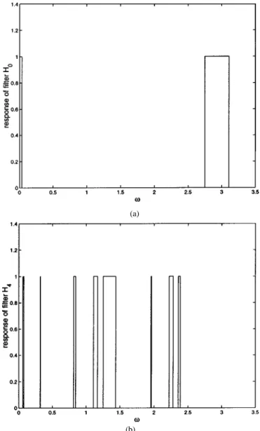
Ideal FB [contiguous stacking, Fig. 3(b)]: 1.28 mW Ideal PCFB (unconstrained class ): 0.94 mW The PCFB is, therefore, significantly better than the other filter banks. Compared to the traditional DFT, the savings in power is about a factor of five. Fig. 9 shows the responses of two of the eight filters in the PCFB (normalized to unity). Notice that the filters have multiple passbands. The plot for shows that its practical implementation could be expensive because of the very narrow passbands. In fact, by a slight variation of the PCFB design algorithm, it is possible to eliminate bands that are narrower than a certain threshold. Such near-PCFB solutions will still have performance close to ideal. In any case, it is our opinion that the primary role of the PCFB is to provide bounds on performance for fixed . If the performance gap between a practical system and the PCFB solution is small in a particular application, this gives the assurance that we are not very far from optimality.
If we plot the required transmitted power as a function of the number of bands (with all other parameters as in the pre-vious example) the result is as shown in Fig. 10. The plot shows the results for 1, 2, 4, 8, 16, 32, 64, and 128. The PCFB requires smaller power than all other methods (consistent with its theoretical optimality). However, the difference between var-ious filter banks becomes negligible as increases. This is analogous to a well-known observation in subband coding [14]; namely the coding gain is relatively insensitive to the choice of filter bank as . DMT systems based on fixed filter banks such as the DFT or cosine modulated filter banks are at-tractive because of their simplicity; they are non adaptive and can be implemented efficiently [10], [27].
VII. SCALARPREFILTERINGBEFORECHANNEL Consider again, Fig. 1 where is orthonormal with
. Assume as before that has been equalized by inserting . Suppose this configuration is further modified by insertion of a prefilter and postfilter around the channel [Fig. 11(a)]. Thus the effective transmitting
filters are and receiving filters are
. This defines a biorthogonal filter bank . This system can achieve better performance
(a)
(b)
Fig. 9. Two of theM filters in the PCFB which minimizes transmitted power in the example.
Fig. 10. A comparison of the PCFB with other filter banks as a function of number of bandsM.
than the orthonormal system . For example, we
can shape and such that the transmitted power
is minimized for fixed bit rates and probabilities of error.
in the th symbol is this variance averaged over a period. To find this, redraw Fig. 11(b) as in Fig. 11(c) where are
the polyphase components of . We shall assume
that the symbols are white with zero mean and variance . This is consistent with the view that is generated by parsing a binary i.i.d. sequence [8]. Thus the variance at the
output of is given by . The
average variance of is then
Assuming further that are uncorrelated for different , the total power input to the channel is the sum of these average variances
(21)
The quantity is also the physical signal-power at the input of the detector. The noise variance at the detector input can be computed by referring to Fig. 2(c) and inserting the additional factor in the noise transfer functions. Thus
Since for some , the total power is
where we have substituted the preceding expression for and
used the fact that for any orthonormal filter
bank. For a given channel, and are fixed.
As-sume the set of error probabilities and bit rates are also fixed. The total power input to the channel then depends on
the orthonormal filter bank and the prefilter .
The next result shows how this power can be minimized. It is an extension to the DMT system, of a familiar result in the subband coding theory [12].
Theorem 1: Optimum Prefiltered Orthonormal FB for DMT: Assume that the modulation symbols are white, and uncorrelated for different . For fixed probabilities of error and bit rates , the combination of orthonormal filter bank and prefilter which minimizes the total required power is obtained as follows: 1) Choose
with magnitude response (22); 2) Make PCFB for
(a)
(b) (c)
Fig. 11. (a) Pre and post filters in the DMT system. (b) Thekth subchannel symbol and its interpolation. (c) Equivalent polyphase diagram.
Proof: From the Cauchy–Schwartz inequality we have
where the argument has been eliminated for simplicity. Equality holds when the two integrands on the left are equal, that is,
(22) This is the optimum no matter what the orthonormal filter bank is. With the prefilter chosen as above, the total
transmitted power is where
Thus, is a concave function of
which can be regarded as a subband variance vector from an orthonormal analysis bank with input power spectrum . Applying the result of Section IV we conclude that the orthonormal filter bank mini-mizing the total power is a PCFB for the power spectrum
.
Note that the solution (22) also arises in optimal prefiltering prior to scalar quantization, and is said to be the half whitening
filter [14], [36] for the spectrum .
VIII. CONCLUDINGREMARKS
The DMT idea is similar in principle to subband coding where a signal to be quantized is first decomposed into sub-bands. Depending on the power spectrum of the input, there is a certain distribution of signal energy across the sub-bands. This distribution is exploited in the coding process by op-timal bit allocation: we allocate more bits to the subband having
higher energy. Thus, in the subband coder, the frequency depen-dence of the input signal is exploited. In the DMT system, the frequency dependence of the channel and the noise are exploited. The similarity of the two problems is exemplified by the fact that the PCFB serves as an optimal the-oretical benchmark in both cases. The complete duality between the optimization of subband coders and DMT systems can also be seen in a more basic way as explained in [21]. The use of nonuniform filter banks and PCFBs for DMT communication has not been addressed in this paper. Such an extension finds application in the so-called DWMT (discrete wavelet multitone) modulation. We conclude with one further remark. The implicit assumption throughout has been that the channel and the noise power spectrum are entirely known so that the optimal filter bank can be identified. If there is an error in the estimation of these channel parameters, then naturally the performance would be suboptimal. An interesting research problem in this context would be to analyze the extent to which the results will stray from optimality.
APPENDIX A
PARSINGSTAGE INDMT COMMUNICATION
Fig. 12(a) shows the first stage of multitone modulation [8], [10] called the parsing stage. Here represents binary
data to be transmitted over a channel. This data is divided
into nonoverlapping -bit blocks. The bits in each block are partitioned into groups, the th group being a collection of bits (demonstrated in the figure for ). Thus, the total
number of bits per block can be expressed as .
The b in the th group constitute the th symbol which can therefore be regarded as a -b number. For the th block, this symbol is denoted as . This is the modulation symbol
for the th band. The vector is
sometimes referred to as the DMT symbol. For the case of pulse amplitude modulation (PAM), the sample is a quantized real number as demonstrated in Fig. 12(c) for . For the
(a) (b)
(c) (d)
Fig. 12. (a) and (b) Explanation of the parsing stage in DMT. (c) The 8-PAM constellation (3 b). (d) the 16-QAM constellation (4 b).
case of quadrature amplitude modulation (QAM) can be regarded as a complex number, taking one of possible values from a rectangular constellation as demonstrated in Fig. 12(d). More efficient constellations exist [26].
APPENDIX B
PROOF OFCONVEXITY OFBITRATE
The following proof was first presented in [6]. Consider (8) and delete all dependence on for simplicity. Without using the
approximation we will show that is convex in .
First notice that
As increases from to , the
quan-tity decreases from to zero. We will show that is
convex for . Since the inverse of a decreasing
convex function is convex (Appendix C), this will prove that is convex in . For convenience define
Then, , and becomes
where the primes denote derivatives with respect to . We know is convex if its second derivative is nonnegative. So it is
sufficient to show that is decreasing. Both and
are positive and decreasing in ,
and so as well. It is therefore sufficient to show that
decreases. Since , it
follows that . Similarly, the
func-tion has derivative .
Using these we verify that
where . Now the range
translates to . In this range,
is decreasing. So, it is sufficient to show that is decreasing in , or its derivative is negative.
This is equivalent to showing that . Now
Using integration by parts this indeed becomes
APPENDIX C
DECREASINGCONVEXFUNCTIONS
To verify that the inverse of a decreasing convex function is convex, let be an invertible convex function (in some
range ). We have
for . Substituting and
, and similarly for , we get
If is a decreasing function, then this implies
REFERENCES
[1] A. N. Akansu, P. Duhamel, X. Lin, and M. de. Courville, “Orthogonal transmultiplexers in communications: A review,” IEEE Trans. Signal
Processing, vol. 46, pp. 979–995, Apr. 1998.
[2] S. Akkarakaran and P. P. Vaidyanathan, “On optimization of filter banks with denoising applications,” in Proc. IEEE ISCAS’99, Orlando, FL, June 1999.
[3] , “The role of principal component filter banks in noise reduction,” in Proc. SPIE, Denver, CO, July 1999.
[4] , “Filter bank optimization with convex objectives, and the opti-mality of principal component forms,” IEEE Trans. Signal Processing, vol. 49, pp. 100–114, Jan. 2001.
[5] , “Results on principal component filter banks: Colored noise sup-pression and existence issues,” IEEE Trans. Inform. Theory, to be pub-lished.
[6] , “Discrete multitone communication with principal component filter banks,” in Proc. IEEE Int. Conf. Communications (ICC), Helsinki, Finland, June 2001.
[7] N. Al-Dhahir and J. M. Cioffi, “Block transmission over dispersive chan-nels: Transmit filter optimization and realization, and MMSE-DFE re-ceiver performance,” IEEE Trans. Inform. Theory, vol. 42, pp. 137–160, Jan. 1996.
[8] J. A. C. Bingham, “Multicarrier modulation for data transmission: An idea whose time has come,” IEEE Commun. Mag., pp. 5–14, May 1990. [9] G. Cherubini, E. Eleftheriou, S. Olcer, and J. M. Cioffi, “Filter bank modulation techniques for very high speed digital subscriber lines,”
IEEE Commun. Mag., pp. 98–104, May 2000.
[10] J. S. Chow, J. C. Tu, and J. M. Cioffi, “A discrete multitone transreceiver system for HDSL applications,” IEEE J. Select. Areas Commun., vol. 9, pp. 895–908, Aug. 1991.
[11] T. M. Cover and J. A. Thomas, Elements of Information Theory. New York: Wiley, 1991.
[12] I. Djokovic and P. P. Vaidyanathan, “On optimal analysis/synthesis fil-ters for coding gain optimization,” IEEE Trans. Signal Processing, vol. 44, pp. 1276–1279, May 1996.
[13] G. B. Giannakis, “Filter banks for blind channel identification and equal-ization,” IEEE Signal Processing Lett., vol. 4, pp. 184–187, June 1997. [14] N. S. Jayant and P. Noll, Digital Coding of Waveforms. Englewood
Cliffs, NJ: Prentice-Hall, 1984.
[15] I. Kalet, “The multitone channel,” IEEE Trans. Commun., vol. 37, pp. 119–124, Feb. 1989.
[16] I. Kalet and S. Shlomo, “On the capacity of a twisted-wire pair: Gaussian model,” IEEE Trans. Commun., vol. 38, pp. 379–383, Mar. 1990. [17] I. Kalet, “Multitone modulation,” in Subband and Wavelet Transforms,
A. N. Akansu and M. J. Smith, Eds. Norwell, MA: Kluwer , 1996. [18] J. K. Kerpez, “Near-end crosstalk is almost Gaussian,” IEEE Trans.
Commun., vol. 41, pp. 670–672, Jan. 1993.
[19] B. P. Lathi, Modern Digital and Analog Communication
Sys-tems. Oxford, U.K.: Oxford Univ. Press, 1998.
[20] X. Lin and A. N. Akansu, “A distortion analysis and optimal design of orthonormal basis for DMT receivers,” in Proc. ICASSP’96, 1996, pp. 1475–1478.
[21] Y. P. Lin, P. P. Vaidyanathan, S. Akkarakaran, and S.-M. Phoong, “On the duality of optimal DMT systems and biorthogonal subband coders,” in Proc. ICASSP’00, Istanbul, Turkey, June 2000.
[22] Y.-P. Lin and S.M. Phoong, “Perfect discrete multitone modulation with optimal transceivers,” IEEE Trans. Signal Processing, vol. 48, pp. 1702–1712, June 2000.
[23] P. Moulin, “A new look at signal-adapted QMF bank design,” in Proc.
ICASSP’95, Detroit, MI, May 1995, pp. 1312–1315.
[24] P. Moulin, M. Anitescu, and K. Ramchandran, “Theory of rate-distortion optimal, constrained filter banks—Applications to IIR and FIR biorthog-onal designs,” IEEE Trans. Signal Processing, vol. 48, pp. 1120–1132, Apr. 2000.
[25] D. Pal, G. N. Iyengar, and J. M. Cioffi, “A new method of channel short-ening with applications to discrete multitone (DMT) systems,” in Proc.
IEEE Int. Conf. Communications, vol. 2, 1998, pp. 763–768.
[26] J. G. Proakis, Digital Communications. New York: McGraw Hill, 1995.
[27] A. D. Rizos, J. G. Proakis, and T. Q. Nguyen, “Comparison of DFT and cosine modulated filter banks in multicarrier modulation,” in Proc.
Globecom’94, Nov. 1994, pp. 687–691.
[28] A. Scaglione, G. B. Giannakis, and S. Barbarossa, “Redundant filter bank precoders and equalizers Part I: Unification and optimal designs,”
IEEE Trans. Signal Processing, vol. 47, pp. 1988–2006, July 1999.
[29] , “Redundant filter bank precoders and equalizers—Part II: Syn-chronization and direct equalization,” IEEE Trans. Signal Processing, vol. 47, pp. 2007–2022, July 1999.
[30] A. Scaglione, S. Barbarossa, and G. B. Giannakis, “Filterbank trans-ceivers optimizing information rate in block transmissions over disper-sive channels,” IEEE Trans. Inform. Theory, vol. 45, pp. 1019–1032, Apr. 1999.
[31] T. Starr, J. M. Cioffi, and P. J. Silverman, Understanding Digital
Sub-scriber Line Technology. Englewood Cliffs, NJ: Prentice-Hall, 1999. [32] M. K. Tsatsanis and G. B. Giannakis, “Principal component filter banks
for optimal multiresolution analysis,” IEEE Trans. Signal Processing, vol. 43, pp. 1766–1777, Aug. 1995.
[33] M. A. Tzannes, M. C. Tzannes, J. G. Proakis, and P. N. Heller, “DMT systems, DWMT systems, and digital filter banks,” in Proc. ICC’94, 1994, pp. 311–315.
[34] M. Unser, “On the optimality of ideal filters for pyramid and wavelet signal approximation,” IEEE Trans. Signal Processing, vol. 41, pp. 3591–3596, Dec. 1993.
[35] , “An extension of the KLT for wavelets and perfect reconstruction filter banks,” in Proc. Conf. Wavelet Applications in Signal and Image, San Diego, CA, 1993, pp. 45–56.
[36] P. P. Vaidyanathan, Multirate Systems and Filter Banks. Englewood Cliffs, NJ: Prentice-Hall, 1993.
[37] , “Theory of optimal orthonormal subband coders,” IEEE Trans.
Signal Processing, vol. 46, pp. 1528–1543, June 1998.
[38] P. P. Vaidyanathan, Y.-P. Lin, S. Akkarakaran, and S.-M. Phoong, “Opti-malilty of principal component filter banks for discrete multitone com-munication systems,” in Proc. IEEE ISCAS’00, Geneva, Switzerland, May 2000.
[39] , “Optimizing the capacity of orthogonal and biorthogonal DMT channels,” in Proc. EUSIPCO’00, Tampere, Finland, Sept. 2000. [40] P. P. Vaidyanathan and S. Akkarakaran, “A review of the theory and
applications of optimal subband and transform coders,” J. Appl. Comput.
Harmonic Analysis, to be published.
[41] L. Vandendorpe, L. Cuvelier, F. Deryck, J. Louveaux, and O. van de Wiel, “Fractionally spaced linear and decision feedback detectors for transmultiplexers,” IEEE Trans. Signal Processing, vol. 46, pp. 996–1011, Apr. 1998.
[42] M. Vetterli and J. Kova˘cevic´, Wavelets and Subband Coding. Englewood Cliffs, NJ: Prentice-Hall, 1995.
[43] J.-J. Werner, “The HDSL environment,” IEEE J. Select. Areas in
Commun., vol. 9, pp. 785–800, Aug. 1991.
[44] X.-G. Xia, “New precoding for intersymbol interference cancellation using nonmaximally decimated multirate filter banks with ideal FIR equalizers,” IEEE Trans. Signal Processing, vol. 45, pp. 2431–2441, Oct. 1997.
[45] , “Filterbank precoders for blind equalization: Polynomial ambi-guity resistant precoders (PARP),” IEEE Trans. Circuits Syst. I, vol. 48, pp. 193–209, Feb. 2001.
[46] B. Xuan and R. H. Bamberger, “FIR principal component filter banks,”
IEEE Trans. Signal Processing, vol. 46, pp. 930–940, Apr. 1998.
P. P. Vaidyanathan (S’80–M’83–SM’88–F’91) was born in Calcutta, India, on Oct. 16, 1954. He received the B.Sc. (Hons.) degree in physics and the B.Tech. and M.Tech. degrees in radiophysics and electronics, all from the University of Calcutta, India, in 1974, 1977, and 1979, respectively, and the Ph.D. degree in electrical and computer engineering from the Univer-sity of California at Santa Barbara in 1982.
He was a Postdoctoral Fellow at the University of California, Santa Barbara from September 1982 to March 1983. In March 1983, he joined the Electrical Engineering Department of the California Institute of Technology, Pasadena, as an Assistant Professor, and since 1993, has been Professor of electrical engi-neering there. His main research interests are in digital signal processing, mul-tirate systems, wavelet transforms and signal processing for digital communi-cations.
and is currently an Associate Editor for the journal IEEESIGNALPROCESSING
LETTERS, and a Consulting Editor for the journal Applied and Computational
Harmonic Analysis. He has been a Guest Editor in 1998 for special issues of the
IEEE TRANSACTIONS ONSIGNALPROCESSINGand the IEEE TRANSACTIONS ON CIRCUITS ANDSYSTEMSII, on the topics of filter banks, wavelets and subband coders. He has authored a number of papers in IEEE journals, and is the author of the book Multirate Systems and Filter Banks. (NJ, Englewood Cliffs: Prentice Hall, 1993). He has written several chapters for various signal processing handbooks. He was a recipient of the Award for excellence in teaching at the California Institute of Technology for the years 1983–1984, 1992–1993, and 1993–1994. He also received the NSF’s Presidential Young Investigator Award in 1986. In 1989 he received the IEEE ASSP Senior Award for his paper on multirate perfect-reconstruction filter banks. In 1990 he was recipient of the S. K. Mitra Memorial Award from the Institute of Electronics and Telecommunications Engineers, India, for his joint paper in the IETE journal. He was also the coauthor of a paper on linear-phase perfect reconstruction filter banks in the IEEE SP TRANSACTIONS, for which the first author (Truong Nguyen) received the Young Outstanding Author Award in 1993. He received the 1995 F. E. Terman Award of the American Society for Engineering Education, sponsored by Hewlett Packard Co., for his contributions to engineering education, especially the book Multirate
Systems and Filter Banks. He has given several plenary talks including at the
Sampta’01, Eusipco’98, SPCOM’95, and Asilomar’88 conferences on signal processing. He has been chosen a distinguished lecturer for the IEEE Signal Processing Society for the year 1996–1997. In 1999, he was chosen to receive the IEEE CAS Society’s Golden Jubilee Medal. He is a recipient of the IEEE Signal Processing Society’s Technical Achievement Award for the year 2002.
Yuan-Pei Lin (S’93–M’97) was born in Taipei, Taiwan, R.O.C., in1970. She received the B.S. degree in control engineering from the National Chiao-Tung University, Hsinchu, Taiwan, R.O.C., in 1992, and the M.S. and Ph.D. degrees, both in electrical engineering from California Institute of Technology, Pasadena, in 1993 and 1997, respec-tively.
She joined the Department of Electrical and Con-trol Engineering of National Chiao-Tung University in 1997. Her research interests include multirate filter banks, wavelets and applications to communication systems. She is currently an Associate Editor for Multidimensional Systems and Signal Processing.
Pasadena, both in electrical engineering, in 1997 and 2001, respectively.
Since July 2001, he has been with Sequoia Communications Corp., Los Angeles, working on designing the baseband processor for a WCDMA mobile receiver. His doctoral thesis was on filter bank optimization with communications and noise suppression applications. His research interests are wireless communications, CDMA and OFDM systems, filter banks and wavelets, and digital signal processing for communications.
See-May Phoong (S’93–A’96) was born in Johor, Malaysia, in 1968. He received the B.S. degree in electrical engineering from the National Taiwan University, Taipei, Taiwan, in 1991, and the M.S. and Ph.D. degrees in electrical engineering from the California Institute of Technology (Caltech), Pasadena, in 1992 and 1996, respectively.
He joined the faculty of the Department of Elec-tronic and Electrical Engineering, Nanyang Techno-logical University, Singapore, from September 1996 to September 1997. In September 1997, he joined the Graduate Institute of Communication Engineering, National Taiwan University , Taipei, Taiwan, as an Assistant Professor and since 2002, he has been an As-sociate Professor. His interests include multirate signal processing, filter banks and their application to communications.
Dr. Phoong is currently an Associate Editor for IEEE TRANSACTIONS ON
CIRCUITS ANDSYSTEMSII, and IEEE SIGNALPROCESSINGLETTERS. He is the recipient of the Wilts Prize (1997) for outstanding independent research in Elec-trical Engineering at Caltech.