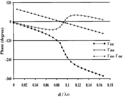
Figure 7 Phase of the reflection coefficients of the asymmetric microstrip coupled line open end shown in Figure 1
mode is found to become significant when the path difference between the two coupled lines is close to a distance which corresponds to the quarter of the waveguide wavelength associated with the loaded microstrip line. Naturally, this
Ž .
critical distance drlg f 0.25 may have been predicted by a qualitative argument according to a quasi-TEM
approxima-Ž
tion in this case, one of the two coupled lines is an open end, and the other one is loaded by a short circuit according to the
.
distance d . Nevertheless, quantitative results are given by the matrix pencil method, and the reflection coefficients of the discontinuity, as a function of the parameter drlo, are determined with accuracy. However, these results demon-strate the efficiency of the matrix pencil technique in the study of multiple-mode devices. Associated with a full-wave approach, this posttreatment does not present any restriction regarding the geometry or the frequency as a quasi-TEM approach.
REFERENCES
1. A. A. Omar and Y. L. Chow, ‘‘Coplanar Waveguide with Top and Bottom Shields in Place of Air Bridges,’’ IEEE Trans. Microwa¨e Theory Tech., Vol. 41, Sept. 1993, pp. 1559]1563.
2. N. I. Dib, M. Gupta, G. E. Ponchak, and L. P. B. Katehi, ‘‘Characterization of Asymmetric Coplanar Waveguide Disconti-nuities,’’ IEEE Trans. Microwa¨e Theory Tech., Vol. 41, Sept.
1993, pp. 1549]1558.
3. R. W. Jackson, ‘‘Mode Conversion at Discontinuities in Finite-Width Conductor-Backed Coplanar Waveguide,’’ IEEE Trans.
Microwa¨e Theory Tech., Vol. 37, Oct. 1989, pp. 1582]1589.
4. C.-L. Lee, Y. Liu, and T. Itoh, ‘‘The Effects of the Coupled Slotline Mode and Air-Bridges on CPW and NLC Waveguide Discontinuities,’’ IEEE Trans. Microwa¨e Theory Tech., Vol. 43,
Dec. 1995, pp. 2759]2765.
5. P. Etre and A. Sadigh, ‘‘Wireless Applications for Electromag-netic Tools,’’ Proc. ESA Workshop Ad¨anced CAD for Microwa¨e Filters and Passi¨e De¨ices, ESTEC, Noordwijk, The Netherlands,
Nov. 1995, pp. 105]129.
6. R. H. Jansen, P. Hildenhagen, D. G. Swanson, and A. John, ‘‘Design and Optimisation of High-Order MM-Wave Filters Us-ing 2D and 2.5D Electromagnetic Tools,’’ Proc. ESA Workshop
Ad¨anced CAD for Microwa¨e Filters and Passi¨e De¨ices, ESTEC,
Noordwijk, The Netherlands, Nov. 1995, pp. 349]360.
7. T. Becks and I. Wolff, ‘‘Analysis of 3-D Metallization Structure by a Full-Wave Spectral Domain Technique,’’ IEEE Trans.
Mi-crowa¨e Theory Tech., Vol. 40, Dec. 1992, pp. 2219]2227.
8. N. K. Das and D. M. Pozar, ‘‘A Generalized Spectral-Domain Green’s Function for Multilayer Dielectric Substrates with Appli-cation to Multilayer Transmission Lines,’’ IEEE Trans.
Mi-crowa¨e Theory Tech., Vol. MTT-35, Mar. 1987, pp. 326]335.
9. Y. Hua and T. Sarkar, ‘‘Generalized Pencil-of-Function Method for Extracting Poles of an EM System from Its Transient Re-sponse,’’ IEEE Trans. Antennas Propagat., Vol. 37, Feb. 1989, pp. 229]234.
10. Y. Hua and T. Sarkar, ‘‘Matrix pencil method for estimating parameters of exponentially dampedrundamped sinusoids in noise,’’ IEEE Trans. Acoust., Speech, Signal Processing, Vol. 38, May 1990, pp. 814]824.
11. M.-D. Wu, S.-M. Deng, R.-B. Wu, and P. Hsu, ‘‘Full-Wave Characterization of the Mode Conversion in a Coplanar Wave-guide Right-Angled Bend,’’ IEEE Trans. Microwa¨e Theory Tech.,
Vol. 43, Nov. 1995, pp. 2532]2538.
12. C. Delabie, ‘‘Elaboration d’un Simulateur de Dispositifs Planaires Microondes. Application a la Caracterisation de Materiaux Supraconducteurs,’’ These de Doctorat, Universite des Sciences` ´ et Technologies de Lille, France, Sept. 1994.
13. G. Splitt, ‘‘A Rapid Method for Arbitrary Microstrip Structure Using the FFT-Algorithm,’’ Proc. 20th EMC, Sept. 1990, pp. 1481]1486.
14. W. P. Harokopus and L. P. B. Katehi, ‘‘Characterization of Microstrip Discontinuities on Multilayer Dielectric Substrates Including Radiation Losses,’’ IEEE Trans. Microwa¨e Theory Tech., Vol. 37, Dec. 1989, pp. 2058]2065.
15. N. I. Dib, L. P. B. Katehi, G. E. Ponchak, and R. N. Simons, ‘‘Theoretical and Experimental Characterization of Coplanar Waveguide Discontinuities for Filter Applications,’’ IEEE Trans.
Microwa¨e Theory Tech., Vol. 39, May 1991, pp. 873]881.
16. F. Huret, ‘‘Etude Comparative de L’approche dans le Domaine ´
Spectral et de la Methode des Equations Integrales Singulieres´ ´ ` pour la Simulation des Lignes Planaires en Technologie Mono-lithique Microonde,’’ These de Doctorat, Universite des Sciences´ ´ et Technologies de Lille, France, Dec. 1991.
Q 1998 John Wiley & Sons, Inc. CCC 0895-2477r98
AN ACTIVE FREQUENCY-TUNED
BEAM-SCANNING
LEAKY-WAVE ANTENNA
Cheng Chi Hu1, Jin Jei Wu,1and Christina F. Jou1
1Institute of Communication Engineering
National Chiao Tung University Hsinchu, Taiwan, R.O.C.
Recei¨ed 21 July 1997
ABSTRACT: A frequency-tuned beam-scanning antenna is de¨eloped, which integrated a microstrip leaky-wa¨e antenna with a¨aractor-tuned HEMT VCO as the source. The microstrip leaky-wa¨e antenna is operated in the first higher mode. To excite the first higher mode, the microstrip leaky-wa¨e antenna is fed asymmetrically. The dominant mode excitation has been successfully suppressed by adding a sequence of co¨ered wire in the center of the microstrip leaky-wa¨e antenna. The HEMT oscillator frequency is controlled by tuning the¨aractor dc bias, and the beam scanning is demonstrated. The measured scanning angle agrees well with the prediction; it is close to 308 as the VCO frequency is tuned from 8.06 to 9 GHz.Q 1998 John Wiley & Sons, Inc. Microwave
Opt Technol Lett 17: 43]45, 1998.
Key words: leaky-wa¨e antenna; frequency scanning;¨aractor-tuned VCO
I. INTRODUCTION
Frequency scanning is an effective technique for providing antenna beam steering which has been implemented with microstrip technology in recent years. Frequency scanning can be a cost-effective alternative to phase scanning in cer-tain applications because phase shift elements and their associated drivers are not required to steer the antenna beam. Recently, there has been a growing interest in active antenna integration using the microstrip leaky-wave antenna as a frequency scanning element 1, 2. The microstrip leaky-wave antenna is not a low-loss element. However, it also has the advantages of having a low profile, simple structure, easy fabrication, easy matching, frequency scanning, narrow beam, and it is very suitable for active integrated antenna applica-tion. Here, in this letter, the microstrip leaky-wave antenna is
w x fed asymmetrically to excite the first higher mode 3 and leaks in the form of a space wave. In addition, by introducing a sequence of covered wire in the center of the microstrip
Ž .
leaky-wave antenna see Fig. 1 , the excitation of the domi-nant mode can be successfully suppressed and the radiation efficiency can be improved. The characteristic of the mi-crostrip line antenna is determined by its complex propaga-tion constant. Here, an attempt is made to accomplish an active phase-shifterless frequency-scanning antenna by inte-grating a varactor-tuned VCO with a microstrip leaky-wave antenna. The radiation main beam depends on its operating frequency, and the frequency is varied by a varactor in the oscillator resonant circuit; the beam direction is controlled by adjusting the varactor dc bias. Therefore, it can be used as a frequency-scanning antenna.
II. DESIGN OF THE ACTIVE LEAKY-WAVE ANTENNA Figure 1 shows the microstrip realization of the active leaky-wave antenna structure. The varactor-tuned oscillator was designed using a small-signal iterative procedure utilizing a commercially available CAD tool HP-EEsof Libra. A short-circuited microstrip feedback is used in series with the source to provide the device with negative resistance. The leaky-wave antenna is connected to the drain to compensate the negative resistance under steady-state operation. A varactor with an open microstrip line connected to the gate is used to set the resonance of the oscillator. To excite the first higher order mode, the microstrip leaky-wave antenna is fed asymmetri-cally. A sequence of covered wire was inserted in the center of the antenna to suppress the propagation of the dominant
Ž
mode whereas the longitudinal current would be zero for the .
first higher mode . In order to understand the radiation properties of such a microstrip leaky-wave antenna, we ob-tained its complex propagation constants b y ja of the first higher microstrip mode in its leaky range, where b is the phase constant and a is the attenuation constant. The
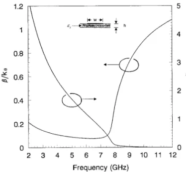
com-Figure 2 Normalized complex propagation constant of the first higher mode for the particular microstrip leaky-wave antenna.
hs 0.508 mm, w s 12 mm, and « s 2.2. k is the free-spacer 0
wavenumber
plex constants are obtained by employing rigorous ŽWiener]Hopf solutions mentioned in 4 . Figure 2 shows. w x the variations of phase constant b and attenuation a as a function of frequency. The geometry and coordinate system of the structure are shown in Figure 3. In our structure, the microstrip leaky-wave antenna is open at the top. For values of b F k , power will leak into a space wave in addition to0
the surface wave. The space wave actually corresponds to radiation at some angle u; the value of this angle changes
Figure 3 Geometry and coordinate system for the microstrip leaky-wave antenna. The antenna is of width ws 12 mm, height
hs 0.508 mm, and length L s 100 mm
Figure 1 Configuration of the active microstrip leaky-wave antenna
MICROWAVE AND OPTICAL TECHNOLOGY LETTERS / Vol. 17, No. 1, January 1998
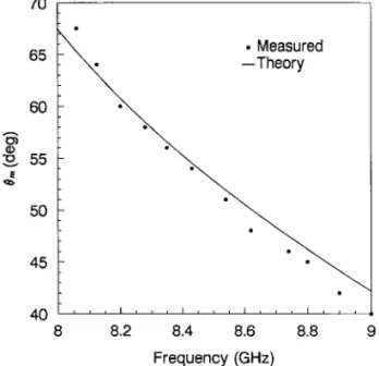
Figure 4 Beam position angel u versus operating frequency ofm the active microstrip leaky-wave antenna
with frequency. By using the approximate relationship u sm
y1Ž .
cos brk , where u is the angle of the beam maximum0 m measured from the z-axis, we can predict the main beam position.
III. EXPERIMENTAL RESULTS
The circuit is designed and fabricated on RTrDuroid sub-strate with a dielectric constant of 2.2 and a thickness of 20 mil. An NEC NE32484 low-noise HEMT is used, and the drain is biased at 2.0 V with a drain current of 10 mA. A
Ž .
GaAs beam lead varactor MrA-COM MA46585 is used as a tuning varactor, which has a capacitance ratio of 10:1 and a capacitor of 0.5 pF at 4 V. For a tuning voltage of 1.0]10 V, the active leaky-wave antenna exhibits a tuning bandwidth of 8.06]9GHz. The variation of scanning angle as a function of frequency is shown in Figure 4, where the beam-scanning angle is close to 308. Figure 5 shows the experimental results of the H-plane patterns for operating frequencies at 8.06 and 9 GHz. We see from Figure 5 that as the operating frequency
Ž .
Figure 5 H-plane y]z plane frequency-scanned radiation
pat-terns
is lower, the beam swings up from the z-axis. Referring to Figure 2, the attenuation constant a decreases as the operat-ing frequency increases, resultoperat-ing in the observed narrower
Ž .
beamwidth in Figure 5. The effective radiated power ERP of this active antenna is about 18 dBm" 2 dBm throughout the frequency-tuning range. The difference in power level of the main beam is caused mainly by the varied impedance of the microstrip leaky-wave antenna.
IV. CONCLUSION
The present work demonstrated the operation principle for electronic beam control where as phase shifters do not enter into the concept. Instead, we utilize the frequency-scanning antenna, the microstrip leaky-wave antenna, as the beam-scanning active antenna. In this letter, an active microstrip leaky-wave antenna capable of frequency scanning has been demonstrated. By tuning the varactor dc bias, beam-scanning control of close to 308 is achieved. The measured beam-scanning angle agrees with the predicted data. The circuit offers a small, simple, lightweight, low-cost tunable source for many microwave applications. And since it is planar, there-fore it is suitable for monolithic circuit integration.
ACKNOWLEDGMENT
The authors wish to acknowledge the financial support of the National Science Council under Contract NSC86-2215-E009-031.
REFERENCES
1. A. A. Oliner, ‘‘A New Class of Scannable Millimeter Wave Anten-nas,’’ Proc. 20 th European Microwa¨es Conf., 1990, pp. 95]104.
2. G.-J. Tou and C.-K. Tzuang, ‘‘Oscillator-Type Active Integrated Antenna: The Leaky-Mode Approach,’’ IEEE Trans. Microwa¨e Theory Tech., Vol. 44, Dec. 1996, pp. 2265]2272.
3. W. Menzel, ‘‘A New Traveling Wave Antenna,’’ Proc. 8th
Euro-pean Microwa¨es Conf., 1978, pp. 302]306.
4. A. A. Oliner and K. S. Lee, ‘‘Microstrip Leaky Wave Strip Anten-nas,’’ 1986 IEEE AP-S Int. Symp. Dig., pp. 443]446.
Q 1998 John Wiley & Sons, Inc. CCC 0895-2477r98
GREEN’S DYADICS FOR
BI-ANISOTROPIC MEDIA WITH
SIMILAR MEDIUM DYADICS
Frank Olyslager1and Ismo V. Lindell2 1Department of Information Technology University of Ghent
B-9000 Ghent, Belgium
2Electromagnetics Laboratory
Helsinki University of Technology FIN-02015 HUT, Finland
Recei¨ed 21 July 1997
ABSTRACT: The Green’s dyadics are constructed for a bi-anisotropic
medium in which the four medium dyadics are proportional to the same dyadic. Since this dyadic is not symmetric, it is not possible to deri¨e the Green’s dyadics from the Green’s dyadics for a bi-isotropic medium by an affine transformation. If one scalar material condition is satisfied it is possible to deri¨e the Green’s dyadics in closed form; otherwise, a one-dimensional integral representation is obtained.Q 1998 John Wiley & Sons, Inc. Microwave Opt Technol Lett 17: 45]47, 1998.