¾¦½üÅX°Ê¦¡¾÷¾¹¤H¾÷ºc¤§¨t²Î¤Æ³]-p(II)
A Systematic Design Methodology for Gear ed Robot Manipulator s(II) -p¹º½s¸¹¡GNSC 88-2212-E-002-013 -p¹º½s¸¹¡G °õ¦æ´Á¶¡¡G¤K¤Q¤C¦~¤K¤ë¤@¤é¦Ü¤K¤Q¤K¦~¤C¤ë¤T¤Q¤@¤é ¥D«ù¤H¡G³¯¹F¤¯¡A°ê¥ß¥xÆW¤j¾Ç°Æ±Ð±Â ºK-n ¥»¬ã¨s¤§¥D-n¥Øªº¥i¤À¬°¨â³¡¥÷¡A²Ä¤@³¡¥÷¬°°w ¹ï¾¦½ü¦¡¾÷¾¹¤H¾Þ§@¾¹¤§¼Ò²Õ¤Æ³]-p¡A²Ä¤G³¡¥÷¬° µo®i¨t²Î¤Æ¤èªk¦X¦¨¨ã¦³½¢¦X³æ¤¸¤§¾Þ§@¾¹¡C ¹ï©ó²Ä¤@³¡¥÷¡G¦¹¤èªk¬O°ò©ó¾¦½ü¦¡¾÷¾¹¤H¾Þ§@ ¾¹¤§¹B°Êºc³y¥i³Q¤À¸Ñ¬°¼Æ±ø¶Ç°Ê½u¡A¦Ó¶Ç°Ê½u¤S ¥i³Q¤À¸Ñ¬°¿é¤J¤Î¶Ç°Ê³æ¤¸¡A³o¨Ç¿é¤J¡B¶Ç°Ê³æ¤¸ ¥i¥H®Ú¾Ú¨ä±ì¥ó¼Æ¦Ó°Ï¤À¦¨°ò¥»«¬»P©µ®i«¬³æ ¤¸¡C°ò©ó¦X¦¨ªk«h¡A°ò¥»«¬»P©µ®i«¬³æ¤¸¥i¥H¥Î¨Ó ¦X¦¨°ò¥»«¬»P©µ®i«¬¶Ç°Ê½u¡C®Ú¾Ú³æ¤¸ªº¹B°Ê¯S ©Ê¡A³æ¤¸¤S¥i³Q¤ÀÃþ¦¨´¶³q¾¦½ü¨t»P¦æ¬P¾¦½ü¨tªº ¼Ò²Õ¸s¡C¦]¦¹¡A¦bµ¹©wºc³y¯x°}²ÕºA¤§±¡§Î¤U¡A°ò ¥»«¬¶Ç°Ê½u«K¥i¥H¥Î¨Ó§@¬°¦X¦¨¾¦½ü¦¡¾÷¾¹¤H¾Þ §@¾¹¤§°ò¦¡A±µ¤U¨Ó«K¥Ñ¾Þ§@¾¹©Ò»Ýªº¹B°Ê¯S©Ê¬D ¿ï¦X¾Aªº©µ®i«¬¶Ç°Ê½u§ó´«°ò¥»«¬¶Ç°Ê½u¡C¸g¦³¦¹ ¤èªk¡A³]-pªÌ¥i¥H±q³Ì²³æµ²ºc¤§¾Þ§@¾¹µÛ¤â¦A¸g ¥Ñ¹B°Ê¯S¼x¶i¦Ó³]-p¥X¦X¾Aªº¾Þ§@¾¹¼Ò«¬¡C
¹ï©ó²Ä¤G³¡¥÷¡G°w¹ï½¢¦X³æ¤¸¤§¯S©Ê¡A¶i¦Ó±q¤w ¦³ªº¤£¥i¤À¸Ñ¤G¦Û¥Ñ«×¾¦½ü¹B°ÊÁå·j´M¥i¯à¤§½¢ ¦X³æ¤¸¡A³o¨Ç³æ¤¸¨Ì¾Ú¨ä±µÄò©Ê¥i¥H³Q¤ÀÃþ¦¨¡GÂù Ã䦡¡BÀÀÂùÃ䦡»P³æÃ䦡½¢¦X³æ¤¸¡C¦AªÌ¡A¹Ïµeªí ¥Üªk¤§³æ¤¸¤§¦ì¸m»Pºc³y¯x°}¤¤«D¹s¤¸¯À¤§¹ïÀ³ ±¡§Î±N³Q»¡©ú¡C¦b¤wª¾ºc³y¯x°}¤§±¡§Î¤U¡A¬D¿ï¦X ¾A¤§½¢¦X³æ¤¸¶i¦æ¾Þ§@¾¹¤§¦X¦¨¡C¥H¤w°t¸mªº½¢¦X ³æ¤¸¬°°ò©³¡A¥[¤J«D½¢¦X³æ¤¸»P«D½¢¦X¶Ç°Ê½u¡A«h ¦¹¾Þ§@¾¹«K¥i³Q¦X¦¨¡C
ABSTRACT
The objectives of this research are two part: one is to develop systematic methodologies for modular design geared robotic manipulators, and one is to create the GRMs with a jointed unit.
For the first part, this methodology is based on the idea that the kinematic structure of a geared robot manipulator can be decomposed into mechanical transmission lines and mechanical transmission lines into input and transmission units. Admissible input and transmission units are distinguished as basic and extended units according to their number of links. With the principle of composition, basic and extended mechanical transmission lines can be constructed accordingly. According to their kinematic properties, admissible units are classified into modular
groups as ordinary and epicyclic units. Thus, with the given configuration, geared robot manipulators can be created by selecting preferred basic mechanical transmission lines and then extended mechanical transmission lines by their kinematic properties. This approach allows the designer to start from the simplest mechanical structure to a more complex model for a given desired kinematic behavior during the conceptual design stage. For the second part, the characteristics of the jointed units are laid out and a systematic methodology is developed to identify
admissible jointed units from the existing non-fractionated two-dof GKCs. The
correspondence between non-zero elements of columns of a structure matrix and the location of the jointed units in the graph
representation of a GRM will be revealed. Admissible structure matrices of GRMs with jointed unit(s) can be systematic identified. With this methodology, it will be shown that GRMs with jointed unit(s) can be efficiently and systematically enumerated.
1. Introduction
Manipulators using gear trains for power transmission are called geared robotic ma-nipulators (GRMs).
The graph theory is a basis and important tool for the structural and kinematic analysis of the GRMs. Based on the graph theory, Lin and Tsai (1989) and Belfiore and Tsai (1991) proposed different methodologies to construct the GRMs. By comparing the works of Belfiore and Tsai (1991), inconsistent results are found. Chen and Shiue (1996) enumerated admissible input and transmission units to construct the MTL. Based on the enumerated units, they developed an approach to compose the units into MTLs and categorize the enumerated MTLs according to their number of links. However, the structural information and kinematic properties of input and trans-mission units are not addressed. A designer can not get more information form the units.
In addition, some GRMs enumerated by Belfiore and Tsai (1991) can not be obtained by applying the method proposed by Chen and Shieu (1996).
The objects of this thesis is develop an approach for the concept of modular design on GRMs. Furthermore, the characteristic of the GRM proposed by Belfiore and Tsai (1991) will be analyzed to developed a systematic approach to create the kinds of GRMs.
2. Kinematics
An unique canonical graph (Tsai, 1988) can be obtained through edge-reconfiguration of the graph representation of a mechanism such that all edges lying on a thin-edged path traced from the root to any other vertex have different edge labels. From the canonical graph of a mechanism, a revolute-joint-only spanning tree can be obtained by removing all the heavy edges. Each thin-edged path origi-nating from the base and ending at a leaf (Chartrand and Oellermann, 1993) represents an open loop chain (OLC). Among these open loop chains, the one starts from the base and ends at the output link is defined as the equivalent open loop chain (EOLC) (Tsai, 1988). Each link in the EOLC is referred to as a primary link, while all other links in the mechanism are called secondary links. Note that the last link in EOLC, called end effector, is a primary link while the last links in other OLCs are secondary links. A secondary link j is said to be carried by a primary link i if it is connected by primary link i with a thin edge in the canonical graph. The revolute joint that connects two primary links is called a primary joint while the revolute joint that connects one primary link and one secondary link is a secondary joint.
Let Φ and Θ be the angular displacement vectors associated with the actuator-space and joint-space. The vectors at actuator-space and joint-actuator-space can be derived by using fundamental circuit theory and coaxial conditions (Chang and Tsai, 1989) and be written as
Φ = AT Θ (1)
where A is the structure matrix (Chang and Tsai, 1990).
In the structure matrix represents an MTL. From Eq.(1), it is clear that the form of A describes the mechanical coupling of the GRM, i.e., where the input actuators are located
and how the input torques are transmitted to various joints of the EOLC.
a. Disjointed units
A GRM can be decomposed into various sub-graphs according to MTLs by the primary links. By rearranging coaxial links, a pseudo-isomorphic graph (Tsai and Lin, 1989) of the MTLs can be obtained. It also can be seen that an unit is connected to its adjacent unit by sharing a common link as a cut link (Tsai and Lin, 1989). The units corresponding to the same primary links must belong to different MTLs and can be separated by using the primary link as the cut link. For the case of units, they are called as disjointed units. On other words, a disjointed unit in a GRM belong to one and only one MTL. In addition, the MTL only consists the disjointed units is defined as a disjointed MTL.
In the disjointed units series of an MTL, the cut links are called connecting links and a preceding disjointed unit uses its post-connecting link to connect the pre-post-connecting link of its succeeding disjointed unit. In addition, the pre-connecting link of a unit is considered the local input to the unit while the post-connecting link is considered the local output to the unit. Note that, the input and transmission units are all disjointed units. The typical disjointed MTL is shown is Fig. 1, where a input unit is connected with k-1 transmission units (Chen and Shiue, 1996). The connecting links are numbered as j, and j+1, … … ., j+n, and the primary links are numbered as i and i+1, … … , i+n-1, for the input unit and transmission units, respec-tively.
The GRM with all disjointed units are called disjointed GRMs. For the case of GRMs, the resultant joint torque will be affected by the actuator torques which are transmitted by different disjointed units series according to disjointed MTLs.
b. Jointed units
For the GRM show in Fig. 2(a), by rearranging the coaxial links, pseudo-isomorphic graphs of MTLs sub-graph can be obtained and shown in Fig. 2 (b). From Fig. 2 (b), it can be seen the transmission unit < 1, 4, 2> is part of the 2-dof non-fractionated GKC < 1, 5, 6, 4, 2, 7, 8>. Figure 2(b) shows the graph by joining the common links among the MTLs sub-graphs. The torque vectors at joint-space and
actuator-space for the example GRM shown in Fig. 2(a) are related by τ τ τ ξ ξ ξ 10 2 1 3 2 2 4 2 4 4 6 6 5 8 7 4 6 6 5 3 8 8 7 4 6 6 5 1 4 5 1 1 1 0 1 0 0 1 , , , , , , , , , , , , , , ( ) ( ) = + − − e e e e e e e e e e e (2)
where τ1,0, τ2,1 and τ3,2 are the joint torques,
ξ1, ξ4 and ξ5 are the torques applied at input links 1, 4 and 5 respectively, and
ei j, = ±N Ni jis the gear ratio for the gear pair mounted on links i and j.
Form Eq.(2), it can be seen that gear ratio e2,4 appears in two columns of structure matrix. Hence, the second non-zero elements of the second and third column of the structure matrix shown in Eq. (2) are coupled and are called jointed elements of a structure matrix. Correspondingly, the 2-dof non-fractionated GKC enclosed by a dashed rectangle in Fig. 2 (c), is called a jointed unit.
GRMs which consist with at least one jointed unit are called jointed GRMs. Note that the structure matrix of a jointed GRM have two non-zero elements at the same row as jointed elements.
3. Modular design
Let link x be the pre-connecting link and link y be the post-connecting link. the angular displacement between the local input x and primary link p, qx,p, can be represented as a function of the angular displacement between local output y and primary link p, qy,p, as q e e e q g q x p x p y y p TU y p , , , , , ( ) , ( ) = − = − 1 2 2 7 1 (3)
where g(TU-7) is the forward gain associated with (TU-7) (Chen, 1997).
Since (TU-7) is a filppable unit, by choosing link y as the local input and link x as the local output, form Eq.(3.9), angular dis-placements qy,p and qx,p can be related as
q e e e q g q x p p y x y p TU y p , , , , , ( ) , ( ) = − = − 1 2 2 1 1 7 (4) By assigning the primary link as the ground link, kinematic behaviors of input and transmission units can be studied in a similar way as gear trains. For those units in which the axes of none of the gears move relative the primary link while the primary link is assumed fixed, are called ordinary units (OUs). For those units in which the axis of one or more gears moves relative to the primary link while
the primary link is assumed fixed, are called plenary units (PUs).
An MTL which composed only by basic units have with the simplest kinematic structure and is called the basic MTL. The sequence of unit arrangement for a basic n-joint MTL can be expressed as
[(IU-1)1, (TU-1)2, (TU-1)3, … … , (TU-1)n] where the subscript represents the location of the unit in the sequence.
An MTL which is composed by at least one extended unit is called an extended MTL. Hence, an extended MTL can be obtained by replacing any basic unit in a basic MTL by a extended unit. Through determine the number of the extended, it will be seen that the number of admissible extended MTLs increase dramatically. In addition, an MTL which composed by at least one PU is called a extended P-MTL while an MTL with only OUs is called an O-MTL. Fig. 3 shows the creation of a three-joint extended P-MTL by replacing the second unit of a basic three-joint MTL, (TU-1), with an PU, (TU-6). The unit arrangement sequence can be listed as [(IU-1), (TU-6), (TU-1)]
A GRM which is formed by only basic MTLs should be defined as a basic GRM. The construction of a basic GRM can be treated as the problem of choosing basic MTLs according to the desired given configuration. On other hand, a GRM which is formed by at least one extended MTL is called an extended GRM. Extended GRMs can be obtained by replacing any basic MTL in a basic GRM with an extended MTL. Hence, an extended GRM with a given
configuration can be systematically enumerated with anticipated results.
For example of two-dof GRMs with one-joint and two-joint MTLs configuration, mm)1 and mm)2 of the O-GRMs can have the following
combinations: [mm)1, mm)2] = [2, 6] or [4, 4], where mm)1 and mm)2 are the number of links of one-joint and two-joint MTLs. For the first combination, there are one two-link α O-MTL, and five six-link β O-MTL. Thus, there are five six-link O-GRMs of this combination. For the second combination, there are one four-link α O-MTL and one four-link O-MTL. Thus, there is one six-link O-GRMs of this combination. Hence, there are six six-link O-GRMs. For the case of P-GRMs, mm)1 and mm)2 have the following combinations: [mm)1, mm)2] = [2, 6] or [4, 4]. There is six and two P-GRMs for the two
combinations, respectively. Hence, there are eight six-link P-GRMs.
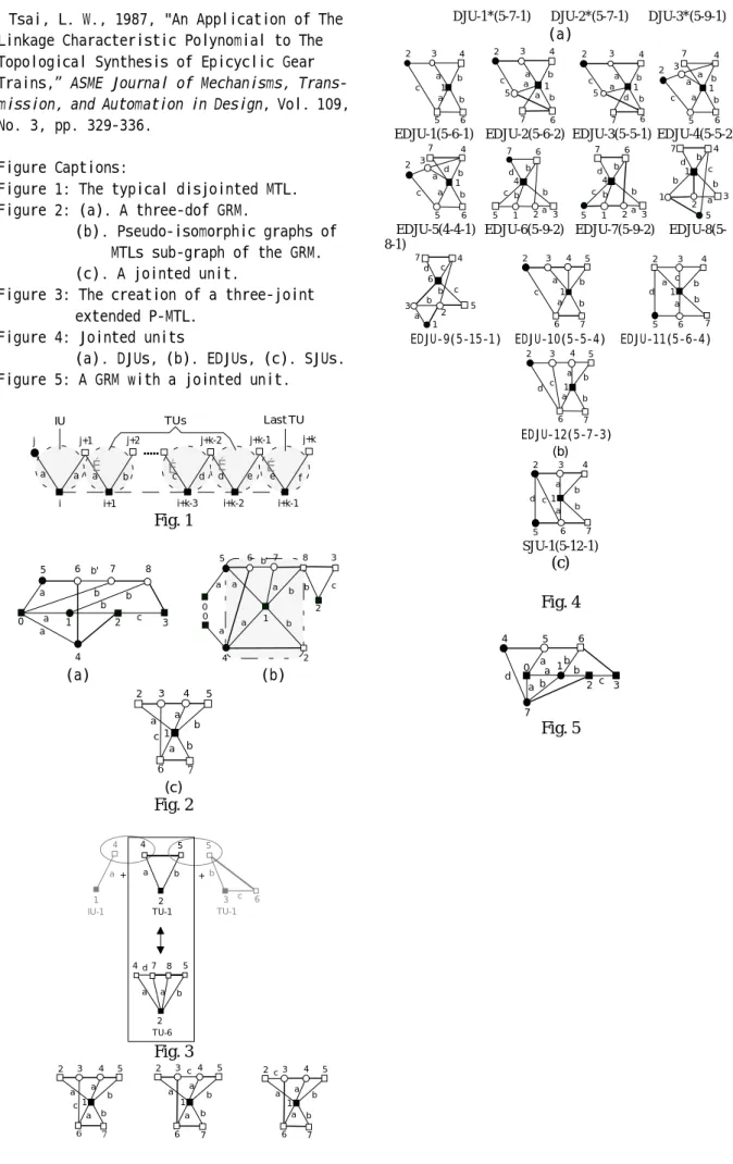
4. Creation of GRMs with a jointed unit Since the jointed unit is a two-DOF GKC, it is clear that the unit needs two local inputs. In general, the joints between local outputs and primary link are assigned as the same articulated joint post-incident with the primary link. Hence, the local outputs of a jointed unit act as the post-connecting links and are coaxial with the primary link. Fundamental rules of a GKC to be used as a jointed unit can be set as follows.
R1. There is one and only one primary link. R2. There are two local outputs act as the
post-connecting links. A jointed unit uses its post-connecting link to connect the pre-connecting link of its succeeding disjointed unit. The post- connecting links are coaxial with the primary link. However, the local inputs of a jointed unit may not necessary act as the pre-connecting link of the unit and/or be assigned as input link. Hence, additional fundamental rule can be set according to the function of the local inputs as follows.
a. Two local input links are pre-connecting links:
The unit is called a double-side jointed unit (DJU). Additional rule for a GKC to be used as a DJU can be set as follow.
R3a. There is a pair of links which are coaxial with the primary link but not coaxial with the post-connecting links. These links are the local input of the unit and are assigned as the pre-connecting links.
b. One local input is a pre-connecting link and the other is an input link:
The unit is called a equivalent double-side jointed units (EDJU). Additional rule for a GKC to be used as a EDJU can be set as follow. R3b. There is two links which are incident with the primary link but not coaxial with the post-connecting links. These two links are the local inputs of the unit and one of them can be assigned as the pre-connecting link.
c. Two local inputs act as input links:
The unit is called a single-side jointed unit (SJU). Note that the joint between an input link and the primary link can not be a gear pair.
With these fundamental rules, admissible jointed units can be identified
systematically from the atlas of two-dof non-fractionated GKCs. The identification
process can be broadly classified into the following stages.
Step 1: Choose primary link and form the thin-edge only canonical spanning tree. Step 2: Assign primary link and post connecting links.
Step 3: Determine local input(s) by checking redundancy.
Step 4: Determine the functions of local inputs.
Figure 4(a) ,(b) and (c) show the SJUs, EDJUs and DJUs, respectively. With the atlas of admissible SJUs, EDJUs and DJUs, the
enumeration of admissible GRMs with a jointed unit can be treated as the problem of choosing proper jointed unit from the atlas of admissible jointed unit according to the form of structure matrix. The enumeration process can be broadly classified into the following stages.
Step 1: Determine the location of joint elements from desired structure matrix. Step 2: Select proper jointed unit from the location of jointed elements
a. The number of input links of jointed unit is zero if there are two non-zero elements preceding the jointed elements. Only DJUs are eligible for the case.
b. The number of input links of jointed unit is one if there is one and only one non-zero element preceding the jointed elements. For this case, EDJUs and DJUs with one pre-connecting link of is assigned as an input link, are eligible.
c. The number of input links of jointed unit is two if there is no non-zero element preceding the jointed elements. For this case, SJUs, EDJUs with the pre-connecting link is assigned as an input link, and DJUs with two pre-connecting links are assigned as input links, are eligible.
Step 3: Add disjointed unit(s) precedes the jointed unit.
Conditions to select proper disjointed unit(s) precedes a jointed unit are:
a. The non-zero element precedes the jointed elements is the first non-zero element in the column, an IU type disjointed unit is used to connect the jointed unit by sharing its post-connecting link with the pre-connecting link of the jointed unit.
b. The non-zero element precedes the jointed elements is not the first non-zero element in
the column, a TU type disjointed unit is used to connect the jointed unit by sharing its post-connecting link with the pre-connecting link of the jointed unit.
Step 4: Add disjointed unit(s) to succeed the jointed unit.
For the purpose of illustration, IU-1 and TU-1 are chosen as the disjointed unit. Figure 4 shows the disjointed units and jointed unit connected in series.
Step 5: Form the articulated joint(s). a. The joint between a pre-connecting link and its incident primary link is assigned as an articulated joint preceding the primary link. b. By assigned the last post-connecting link as a primary link which succeeds its incident primary link, an articulated joint succeeds its incident primary link is formed.
Step 6: Add disjointed MTL.
Figure 5 shows the graph representation of a GRM with a jointed unit.
5. Summary
For the modular design, the disjointed GRM have been defined as the GRM constructed with all disjointed unit (input and transmission unit). With the principle of composition, basic n-joint MTLs and basic n-dof GRM are constructed with basic input and transmission units. By replacing the basic input and/or transmission units, extended MTLs and extended disjointed GRMs can be constructed from practical considerations such as center distance, speed ratio, and relocation of actuators. This approach allow the designer to start from the simplest mechanical structure to more complicated model systematically during the conceptual design stage with insight of kinematic performance.
For the creation of GRMs with a jointed unit, the active rules for seeking jointed units are represented. Based on the searching rules, the jointed units can be specified into three type: SJUs, DJUs and EDJUs. It is showed that how to choice a feasible jointed unit to construct a geared robotic mechanisms with a jointed unit can be efficiently and systematically enumerated. Finally, one advantage of the jointed units for a GRMs will be discussed separately. In order to demonstrate the advantages, we have design a two and three-dof jointed GRM as illustrative examples.
Reference
Belfiore, N. P., and Tsai, L. W., 1991, "A New Methodology for Structural Synthesis of Geared Robotic Wrists,” Paper No. VIB. 5.,
Proceeding of the Second National Conference on Applied Mechanisms and Robotics,
Cincin-nati.
Belfiore, N. P, 1993, "An Atlas of Remote Actuated Bevel Gear Wrist Mechanisms of up to Nine Links,” Journal of Robotics Research, Vol. 12, No. 5, pp. 448-459.
Buchsbaum, F, and Freudenstein, F, 1970, "Synthesis of Kinematic Structure of Geared Kinematic Chains and Other Mechanisms,”
Journal of Mechanisms, Vol. 5, pp. 357-392.
Chang, S. L., and Tsai, L. W., 1990, "To-pological Synthesis of Articulated Gear Mechanisms” IEEE Trans. on Robotics and
Automation, Vol. 6, No. 1, pp. 97-103.
Chang, S. L., and Tsai, L. W., 1993, "On the Redundant-Drive Backlash-Free Robotic Mecha-nisms,” Journal of Mechanical Design, Vol. 115, pp. 247-254.
Chen, Dar Zen, and Shieu, Shiue Chen, 1996, "Topological Synthesis of Geared Robotic Mechanism,” Proceeding of The 1996 ASME Design Engineering Technical Conference and Comput-ers in Engineering Conference 96-DETE/MECH-1024.
Freudenstein, F., 1971, An Application of Boolean Algebra to the Motion of Epicyclic Drives,” ASME Journal of Engineering for
Industry, Vol. 93, pp. 176-182.
Hsu, C. H. 1992, "A Application of Generalized Kinematic Chains to The Struc-tural Synthesis of Non-fractionated Epicyclic Gear Trains,” Proceeding of the 22nd Biennial
ASME Mechanism Conference, Scottsdale,
Ari-zona, DE-Vol.46,pp.451-458.
Kim, J. T., and Kwak, B. M., 1990, "Application of Edge Permutation Group to Structural Synthesis of Epicyclic Gear Trains,” Mechanism and Machine Theory, Vol. 25, No. 5, pp.563-574.
Lin, C. C., and Tsai, L. W., 1989a, "The Creation of Nonfractionated Two Degreeof -Freedom Epicyclic Gear Trains,” ASME Trans., Vol. 111, pp. 524-529.
Ravisankar, R., and Mruthyunjaya, T. S., 1985, "Computerized Synthesis of The struc-ture of Geared Kinematic Chains,” Mechanism
and machine Theory, Vol. 20, No. 5, pp.
Tsai, L. W., 1987, "An Application of The Linkage Characteristic Polynomial to The Topological Synthesis of Epicyclic Gear Trains,” ASME Journal of Mechanisms,
Trans-mission, and Automation in Design, Vol. 109,
No. 3, pp. 329-336. Figure Captions:
Figure 1: The typical disjointed MTL. Figure 2: (a). A three-dof GRM.
(b) . Pseudo-isomorphic graphs of MTLs sub-graph of the GRM. (c) . A jointed unit.
Figure 3: The creation of a three-joint extended P-MTL.
Figure 4: Jointed units
(a) . DJUs, (b). EDJUs, (c). SJUs. Figure 5: A GRM with a jointed unit.
... Last TU TUs IU i i+1 j j+1 j+2 i+k-1 i+k-2 j+k-2 j+k-1 j+k i+k-3 É É É É a a a b c d d e e f Fig. 1 b 0 a 1 2 a 3 b c a 4 5 6 b' 7 b 8 a a 5 0 2 c b 8 b a b a a 6 b'7 4 2 3 0 1 (a) (b) a c b a 1 4 2 3 5 6 b 7 a (c) Fig. 2 4 1 + 4 5 6 b 3 + 5 a b 2 a c
IU-1 TU-1 TU-1
TU-6 4 5 a b 2 7 d 8 a Fig. 3 a c b a 1 4 2 3 5 6 b 7 a a c b a 1 4 2 3 5 6 b 7 a a c b a 1 4 2 3 5 6 b 7 a
DJU-1*(5-7-1) DJU-2*(5-7-1) DJU-3*(5-9-1)
(a) a c b a 1 4 2 3 5 6 b a c a b 1 4 2 3 5 6 b 7 a a c b a 1 4 2 3 5 6 b 7 d a c b a 1 4 2 3 5 6 b 7 a
EDJU-1(5-6-1) EDJU-2(5-6-2) EDJU-3(5-5-1) EDJU-4(5-5-2)
a c b a 1 4 2 3 5 6 b 7 d b a d b 1 7 4 2 3 5 c b 6 b a d b 1 7 4 2 3 5 c b 6 b a d b 1 5 4 2 3 7 1 c b
EDJU-5(4-4-1) EDJU-6(5-9-2) EDJU-7(5-9-2) EDJU-8(5-8-1) b a d b 1 7 4 2 3 5 c c 6 a c b a 1 4 2 3 5 6 b 7 a c b a 1 4 2 3 5 6 b 7 d
EDJU-9(5-15-1) EDJU-10(5-5-4) EDJU-11(5-6-4) a c b a 1 4 2 3 5 6 b 7 d EDJU-12(5-7-3) (b) a c b a 1 4 2 3 5 6 b 7 d SJU-1(5-12-1) (c) Fig. 4 a d b a 1 4 2 3 7 b c b 0 5 6 a Fig. 5