A fast response and large electrically tunable-focusing imaging system based on
switching of two modes of a liquid crystal lens
Hung-Chun Lin and Yi-Hsin Lin
Citation: Applied Physics Letters 97, 063505 (2010); doi: 10.1063/1.3479051
View online: http://dx.doi.org/10.1063/1.3479051
View Table of Contents: http://scitation.aip.org/content/aip/journal/apl/97/6?ver=pdfcov Published by the AIP Publishing
Articles you may be interested in
Tunable-focus liquid crystal Fresnel zone lens based on harmonic diffraction Appl. Phys. Lett. 101, 221121 (2012); 10.1063/1.4769090
Polarization-insensitive liquid crystal Fresnel lens of dynamic focusing in an orthogonal binary configuration Appl. Phys. Lett. 88, 203505 (2006); 10.1063/1.2205158
Strongly frequency dependent focusing efficiency of a concave lens based on two-dimensional photonic crystals
Appl. Phys. Lett. 88, 011102 (2006); 10.1063/1.2159105 Electrically tunable polymer stabilized liquid-crystal lens J. Appl. Phys. 97, 103101 (2005); 10.1063/1.1896436
Wave front control systems based on modal liquid crystal lenses Rev. Sci. Instrum. 71, 3290 (2000); 10.1063/1.1288256
This article is copyrighted as indicated in the article. Reuse of AIP content is subject to the terms at: http://scitation.aip.org/termsconditions. Downloaded to IP: 140.113.38.11 On: Wed, 30 Apr 2014 10:04:07
A fast response and large electrically tunable-focusing imaging system
based on switching of two modes of a liquid crystal lens
Hung-Chun Lin and Yi-Hsin Lina兲
Department of Photonics and Institute of Electro-Optical Engineering, National Chiao Tung University, Hsinchu 30010, Taiwan
共Received 30 June 2010; accepted 20 July 2010; published online 10 August 2010兲
We demonstrated a fast response and large tunable focusing imaging system consisting of a lens module and a liquid crystal 共LC兲 lens based on the switching of two modes of a LC lens: the negative LC lens and positive LC lens. By discarding the conventional operation of a positive LC lens only in the imaging system, large tunable focusing range can be achieve from 300 to 10 cm owning to the phase change between the positive and the negative LC lens; meanwhile, the response time is fast 共⬃433 ms兲. The potential applications are autofocused cell phones, and cameras. © 2010 American Institute of Physics.关doi:10.1063/1.3479051兴
Electrically tunable-focusing imaging system using a liquid crystal共LC兲 lens has many potential applications, such as cell phones, cameras, and the night vision of hand-carried weapons. Compared to the autofocusing image system within mechanical moving parts, such as controlling the lo-cation of a lens module by voice coil motors, the advantages of electrically tunable-focusing imaging system using a LC lens are compact, light weight, and low power consumption. The electrically tunable focal length of LC lenses results from the gradient distribution of refractive indices due to the orientations of LC directors.1–8 However, several problems of LC lenses need to be overcome. The requirement of a polarizer of LC lenses results in a low optical efficiency 共⬃50%兲. Polarizer-free LC lenses are developed using dif-ferent LC modes.9 Under conventional operation of a posi-tive LC lens only in the imaging system, the tunable focusing ranges of LC lenses are usually small because the tunable focusing ranges are determined by the phase changes of the LC lenses which depend on the birefringence of LC materi-als and the thickness of a LC layer. Generally, the birefrin-gence of LC materials is small around ⬃0.1–0.44.10,11 To enlarge the tunable focusing ranges of LC lenses, we can increase the thickness of a LC layer共⬃130 m兲; neverthe-less, the response time is slow共⬃50 s兲.4Complex electrode designs and driving schemes can reduce the response time but are not suitable for practical applications.3,4Ye et al.12,13 showed the engineering performance of the image formation by operating the LC lens in positive and negative modes. However, the tunable focusing range is small共25 to 56 cm or 5 to 12 cm兲 and response time is still slow 共⬃1.8 s兲. Nev-ertheless, the physical mechanism of two mode switching is not clearly discussed.
In this paper, on the basis of switching of two modes of a LC lens, we demonstrate a fast response time and a large tunable focusing range of an imaging system consisting of a lens module and a LC lens. By discarding the conventional operation of a positive LC lens only in the imaging system, we found that we can obtain the large tunable focusing range by the phase changes resulting from switching of two modes: the negative LC lens and the positive LC lens. The main
mechanism is based on the phase change between positive and negative LC lens to achieve the large tunable focusing meanwhile maintaining the thin thickness of the LC layer. In this way, the object can be continuously imaged from 300 to 10 cm; however, the thickness of the LC lens is 25 m to achieve the fast response time共⬃433 ms兲. The potential ap-plications are autofocused cell phones and cameras.
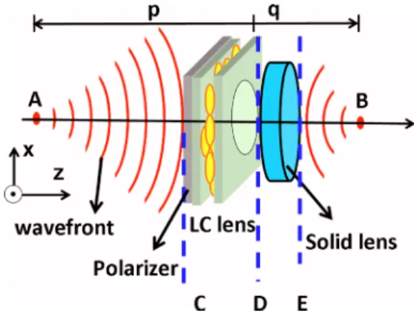
To understand how to achieve a fast response time and a large tunable focusing range of an imaging system, an illus-tration of wave propagation in the image system consisting of a lens module and a LC lens is shown in Fig.1. LC lenses are the phase modulators of light based on inhomogeneous refractive indices of a LC lens originating from the orienta-tions of LC directors controlled by the electric fields in the LC lens. As a result, a LC lens can converts the radius of curvature of wave front. The focal length of the LC lens depending on aperture size共w兲, wavelength, 共兲, and phase difference, 共⌬␦兲, can be expressed as follows:1–8
fLC= ⫻ w
2
4⫻ ⫻ ⌬␦. 共1兲
In Fig.1, the objective distance is p and the image distance is
q. When pⰇw, the parabolic-incident wave 关Eជ1共x,y,z兲兴
ar-riving in front of the lens at the plane C can be expressed as follows:
a兲Electronic mail: [email protected].
FIG. 1. 共Color online兲 The image formation of a combination of a LC lens and a solid lens. A is the location of the objective, B is the location of the image, p is the objective distance and q is the image distance.
APPLIED PHYSICS LETTERS 97, 063505共2010兲
0003-6951/2010/97共6兲/063505/3/$30.00 97, 063505-1 © 2010 American Institute of Physics This article is copyrighted as indicated in the article. Reuse of AIP content is subject to the terms at: http://scitation.aip.org/termsconditions. Downloaded to IP:
Eជ1共x,y,z兲 = Eជ0· e−jk共x 2+y2/2p兲
· e−jk·z, 共2兲
where Eជ0 is amplitude vector and k is the wave number.
Under Fresnel approximation,14 the output wave right after the solid lens at the plane E can be expressed as follows:
ejk共x2+y2/2q兲= e−jk共x2+y2/2p兲· ejk共x2+y2/2f兲· ejk共x2+y2/2fLC共V兲兲, 共3兲 where f is the focal length of the solid lens and fLC共V兲 is the voltage-dependent focal length of the LC lens. In an autofo-cusing imaging system, q is a fixed number determined by the location of an image sensor, and p should be adjusted from infinity to some distance 共p0兲 depending on the
appli-cations. As p changes, fLC共V兲 have to be adjusted
accord-ingly by the applied voltages in order to maintain the relation in Eq.共3兲. In Eq.共3兲, when q equals to f, p equals to fLC共V兲. That means the tunable focusing range of the LC lens deter-mines the tunable objective distance in the whole imaging system. Theoretically, when the imaging system should be eligible for the object at the infinity to p0, fLC共V兲 should be
positive and also be tunable from infinity to p0. However, to
obtain such a LC lens, the LC layer of the LC lens must be thick 共⬃130 m兲 whose response time is slow 共⬃50 s兲 which is not suitable in most of electro-optical applications.4 By reconsidering Eq.共3兲, we can set the image distance not to equal to f. When fLC共V兲Ⰷ0, the image formation is
determined by the solid lens and then Eq. 共3兲turns out
ejk共x2+y2/2q兲= e−jk共x2+y2/2ps兲· ejk共x2+y2/2f兲, 共4兲 where p is defined as ps. Compared Eq.共4兲with Eq.共3兲, the
relationship among p, ps, and fLC共V兲 is as follows:
e−jk共x2+y2/2ps兲= e−jk共x2+y2/2p兲· ejk共x2+y2/2fLC共V兲兲. 共5兲 In Eq. 共5兲, when ps⬍p⬍⬁, the focal length of the LC lens
should be negative. That means the LC lens should be oper-ated as a negative 共or concave兲 lens. When 0⬍p0⬍p⬍ps, the focal length of the LC lens should be positive. That means the LC lens should be operated as a positive共or con-vex兲 lens. Therefore, by switching two lens modes of a LC lens: a positive lens and a negative lens, the conjugated im-age can be formed in point B in Fig. 1 when p is adjusted from infinity to p0. The value of p0 is dependent on the
applications. The large tunable focusing range can thus be achieved. Moreover, the thickness of the LC layer can be reduced since the phase changes resulting from two lens modes, not single positive LC lens only. Therefore, the re-sponse time can be fast; meanwhile, the tunable range of the imaging system is still large.
To demonstrate the concept, we adopted the LC lens based on two-voltage structure which can be operated as a positive lens and a negative lens.7 The structure of the LC lens consists of three indium tin oxide共ITO兲 glass substrates of thickness 0.7 mm, a polymeric layer of NOA81 共Norland Optical Adhesive兲 with thickness of 35 m, and a LC layer with thickness of 25 m. The ITO layer of the middle ITO glass substrate was etched with a hole-pattern within a diam-eter of 2 mm in order to provide an inhomogeneous electric field to LC directors, and the opposite side of such an ITO glass substrate was coated with mechanically buffed polyvi-nylalcohol layer to align LC directors. The bottom ITO glass substrate was also coated with an alignment layer with
me-chanically buffed polyimide layer. The rubbing directions of two alignment layers are antiparallel. The nematic LC mix-ture MLC-2070 共Merck, ⌬n=0.26 for =589.3 nm at 20 ° C兲 was used. The voltage applied between the hole-patterned ITO and the bottom ITO layer was defined as V1. The other applied voltage was defined as V2. When V1⬎V2,
the LC lens is operated as a positive lens. When V1⬍V2, the
LC lens is operated as a negative lens. In the experiments, the laser diode 共=532 nm兲 was used as a light source. A polarizer whose transmissive axis was parallel to the rubbing direction of the LC lens was attached on the LC lens. The measured focal length can be switched from infinity to 16.5 cm under the operation of the positive lens when we apply a voltage of V2 at V1= 90 Vrms. As to the operation of the
negative lens, the absolute value of the measured focal length can be switched from infinity to 20.8 cm when we apply a voltage of V1 at V2= 90 Vrms.
To measure the tunable focusing properties of the imag-ing system, the LC lens and a polarizer were attached on a webcam共Logitech Pro 9000兲. The webcam consists of a lens module with the effective focal length of 3.7 mm and an image sensor with 2 megapixels. After adjusting the location of the image sensor, the image sensor was placed 3.76 mm behind the lens module. According to Eq. 共5兲, the ps should
be 23 cm without a LC lens. After attaching the LC lens with the polarizer on the webcam, we recorded the objective dis-tance of a focused image of a resolution chart by changing the different voltages of the LC lens. The spatial frequency of the resolution chart was 0.625 line pair per millimeter 共lp/mm兲 at p=10 cm and 0.05 lp/mm at p=300 cm. The measured objective distance as functions of lens power of the LC lens is shown in Fig.2. The lens power is defined as the inverse of the focal length. In Fig. 2, the conjugated image can be obtained as the object at p = 300 cm to 10 cm while the LC lens changes the lens power from ⫺4 and 4.85 m−1.
In our imaging system, we adopt two lens mode operation to image the object from 300 to 10 cm. We can calculate the objective distance as a function of the lens power of the LC lens and plotted in Fig. 2 共red solid line兲 based on Eq. 共5兲. The measured results and calculated results are agreeable.
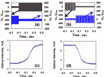
To measure the response time of the imaging system, we measured the response time of the LC lens. When the focal length of the LC lens is switched between ⫺24.9 and 20.6 cm, the response time was 172 ms as the voltage pair switched from 共V1, V2兲=共15 Vrms, 90 Vrms兲 共i.e.,
fLC= −24.9 cm兲 to 共V1, V2兲=共90 Vrms, 20 Vrms兲 共i.e., fLC FIG. 2. 共Color online兲 The objective distance of the imaging system as a function of the lens power of the LC lens. Blue dots represent the measured results and the red line represents the calculated result.
063505-2 H.-C. Lin and Y.-H. Lin Appl. Phys. Lett. 97, 063505共2010兲
This article is copyrighted as indicated in the article. Reuse of AIP content is subject to the terms at: http://scitation.aip.org/termsconditions. Downloaded to IP: 140.113.38.11 On: Wed, 30 Apr 2014 10:04:07
= 20.6 cm兲 and 261 ms from 共V1, V2兲=共90 Vrms, 20 Vrms兲
共i.e., fLC= 20.6 cm兲 to 共V1, V2兲=共15 Vrms, 90 Vrms兲 共i.e.,
fLC= −24.9 cm兲. The results are shown in Figs. 3共a兲–3共d兲.
That means when the object distance is changed between
p = 300 cm and p = 10 cm, the total response time is 433 ms,
compared to conventional lens operation mode, the response time is⬃50 s. Our image system under two lens mode op-erations not only has 100⫻ faster response time but also has large tunable focusing range and is suitable for applications of cell phones and cameras which require response time of 500 ms in general. The fast response time is because of two reasons: one is the thin LC layer共⬃25 m兲 and the other is the voltage effect instead of the slow free-relaxation of LC directors.11 To further improve the response time, we can reduce the viscosity of LC materials, reduce the thickness of the LC layer or add polymer networks to enhance the anchor-ing force.11
Figures 4共a兲–4共c兲show the image performances of the imaging system consisting of a polarizer, the LC lens, a lens
module, and the image sensor. The photos were taken under an ambient white light. The numbers in the photos indicate the locations of the objects. When we switched the voltage pair from 共V1, V2兲=共15 Vrms, 90 Vrms兲 to
共90 Vrms, 90 Vrms兲 to 共90 Vrms, 20 Vrms兲, the clear image
was at 300, 23, and 10 cm. In Fig.4, the image is sharpest at 23 cm because the lens power of the LC lens is 0. As a result, the image quality is determined by lens module. The image is slightly blurred at 10 cm because of the aberration of the LC lens when the LC lens has maximal lens power 共⬃5 m−1兲.
In conclusion, we have demonstrated a fast response and large electrically tunable-focusing range of an imaging sys-tem based on the LC lens based on two lens mode switching. The object can be continuously imaged when the object is at 300 to 10 cm. The response time is around 433 ms. By op-erating two modes of LC lens: the negative lens and positive lens, the phase changes of the LC lens are sufficient to per-form the image per-formation as an object is at 300 to 10 cm despite the thickness of the LC layer is only 25 m. The thin LC layer helps to achieve the fast response time. Such a fast response and large electrically tunable-focusing range of an imaging system is usable in autofocusing cell phones and cameras.
The authors are indebted to Mr. Chuan-Chung Chang 共ITRI兲 for the technical assistance. This research was sup-ported by the National Science Council 共NSC兲 in Taiwan under the Contract No. 98-2112-M-009-017-MY3.
1S. Sato,Jpn. J. Appl. Phys. 18, 1679共1979兲.
2H. Ren, Y. H. Fan, S. Gauza, and S. T. Wu,Appl. Phys. Lett. 84, 4789 共2004兲.
3M. Ye and S. Sato,Mol. Cryst. Liq. Cryst. 433, 229共2005兲. 4B. Wang, M. Ye, and S. Sato,Opt. Commun.250, 266共2005兲. 5Y. H. Lin, H. Ren, K. H. Fang-Chiang, W. K. Choi, S. Gauza, X. Zhu, and
S. T. Wu,Jpn. J. Appl. Phys., Part 1 44, 243共2005兲.
6Y. H. Fan, H. Ren, X. Liang, H. Wang, and S. T. Wu,J. Disp. Technol. 1, 151共2005兲.
7B. Wang, M. Ye, and S. Sato, IEEE Photonics Technol. Lett. 18, 79 共2006兲.
8H. Ren, D. W. Fox, B. Wu, and S. T. Wu,Opt. Express 15, 11328共2007兲. 9Y. H. Lin, H. Ren, and S. T. Wu,Liq. Cryst. Today 17, 2共2008兲. 10S. Gauza, H. Wang, C. H. Wen, S. T. Wu, A. J. Seed, and R. Dabrowski,
Jpn. J. Appl. Phys., Part 1 42, 3463共2003兲.
11S. T. Wu and D. K. Yang, Reflective Liquid Crystal Displays共Wiley, New York, 2001兲.
12M. Ye, B. Wang, S. Yanase, and S. Sato,IEICE Trans. Electron. 91-C, 1599共2008兲.
13M. Ye, B. Wang, M. Kawamura, and S. Sato,Jpn. J. Appl. Phys., Part 1
46, 6776共2007兲.
14B. E. A. Saleh and M. C. Teich, Fundamentals of Photonics共Wiley, New York, 2007兲.
15See supplementary material at http://dx.doi.org/10.1063/1.3479051 for movie files of the image performance of the imaging system.
FIG. 3. 共Color online兲 The measured response time of the LC lens. 共a兲 When the voltage pair is switched from 共V1, V2兲=共15 Vrms, 90 Vrms兲 to 共V1, V2兲=共90 Vrms, 20 Vrms兲, 共c兲 the measured response time of the LC lens is around 172 ms. 共b兲 When the voltage pair is switched from 共V1, V2兲 =共90 Vrms, 20 Vrms兲 to 共V1, V2兲=共15 Vrms, 90 Vrms兲, 共d兲 the measured re-sponse time of the LC lens is around 261 ms.=532 nm.
FIG. 4.共Color online兲 Image performance of the imaging system. The clear image for the objective distance of共a兲 300 cm, 共b兲 23 cm, and 共c兲 10 cm. See Ref.15.
063505-3 H.-C. Lin and Y.-H. Lin Appl. Phys. Lett. 97, 063505共2010兲
This article is copyrighted as indicated in the article. Reuse of AIP content is subject to the terms at: http://scitation.aip.org/termsconditions. Downloaded to IP: 140.113.38.11 On: Wed, 30 Apr 2014 10:04:07