針對爪哇即時編譯器嵌入式系統之區域程式碼分析器與
樣式化區間程式碼優化器
A Local Code Analyzer and Pattern-Based Peephole Optimizer in
Java JIT Compilers for Embedded Systems
研 究 生:黃帥維 Student:Shuai-Wei Huang
指導教授:楊 武 博士 Advisor:Dr. Wuu Yang
國 立 交 通 大 學
網 路 工 程 研 究 所
碩 士 論 文
A ThesisSubmitted to Institute of Networking Engineering College of Computer Science and Information Engineering
National Chiao Tung University in partial Fulfillment of the Requirements
for the Degree of Master
in
Institution of Network Engineering July 2008
Hsinchu, Taiwan, Republic of China
針對爪哇即時編譯器嵌入式系統之區域程式
碼分析器與樣式化區間程式碼優化器
學生:黃帥維
指導教授:楊 武 博士
國立交通大學網路工程所碩士班
摘 要
現今 許多 經移 植過 的嵌 入式 編譯 系統 ,常 由於 指令 集架 構(Instruction Set Architecture,ISA)的不同,無法充分利用新的硬體平台的指令集特性,容易產生效 率較差的程式碼。透過程式原始碼中尋找可優化的指令樣式,可以有效地協助改善 程式碼產生器產生多餘或無效率指令的情況。減少多餘的指令,可降低程式運算時 間,替換為較有效率的指令,可降低存取記憶體次數,進而間接地減少資料快取失 敗的機會,有利於提升整體運算效能。由於透過軟體分析的方式,不需改變硬體, 使得許多學者及研發人員投入其研究,例如,改變程式的暫存器分配演算法、指令 的排程、全域/區域程式碼優化、分支預測、內嵌函式等等。而在嵌入式處理器日漸 普及與多樣的趨勢下,我們觀察到編譯器產生的程式碼與嵌入式處理器的指令集架 構有著密切的關係,不同的指令集架構的差異性,往往隱含著可進一步優化的機會。 因此在本論文中,我們針對爪哇即時編譯器產生的程式碼,除了在區域程式碼分析 器上實作了幾項常見的優化技術外,我們亦針對系統指令集架構的特色,透過遞迴 的方式,協助我們徹底找出新的樣式,藉以改善爪哇即時編譯器上的JCS規則(Java Code Select Rule)與程式產生器(Code emitters),並以Andes處理器指令集架構提出了 幾個常見的可優化樣式。此外,為了驗證各種優化方法所能貢獻的效果,我們設計 了一連串的實驗,以CVM上的即時編譯器作為實驗的平台系統,在系統上實行優化 樣式,探討各個優化技術對系統的影響與改進。Local Code Analyzer and Pattern-Based
Peephole Optimizer in Java JIT Compilers
for Embedded Systems
Student: Shuai-Wei Huang Advisor: Dr. Wuu Yang
Institute of Network Engineering
National Chiao Tung University
Abstract
When a Java JIT compiler is ported to a new hardware platform, it usually cannot take full advantage of the special features of the new platform unless it undergoes thorough and massive optimizing. We propose a new approach to improve the code generator in a ported Java JIT compiler. A static code analyzer is used to automatically discover frequently-occurring patterns in the generated code that are suitable for peephole optimizations. Then the patterns are incorporated in the JIT compiler by modifying instruction selection rules and code emitters. The approach of automatically discovering patterns is feasible because (1) there does exist patterns in the code generated by most compilers and (2) a peephole optimizer requires only quite simple patterns, which can be discovered easily. Our target platform is the Andes architecture, which features several novel hardware facilities. The result of our experiment shows the approach is quite promising.
Keywords: JIT compiler, peephole optimization, pattern matching, embedded system, peephole optimize
誌 謝
這篇論文能夠順利完成,首先我要感謝我的指導教授楊武老師。過去兩年的 研究時光,由於有楊老師的指導,讓我有幸可以接觸編譯技術這門領域,並因此 在知識上能有所增進,如果我的研究有小小的成就,這都必須要歸功於我的指導 教授。楊老師對學生的耐心與對研究的熱忱是大家有目共睹的,也因此我要感謝 老師包容資質駑鈍且表達能力欠缺的我,讓我的研究生活充滿許多珍貴的回憶。 同時我也要感謝產學合作計畫的單教授和徐教授,以及口試的各位教授們,由於 您們的指導與建議,為我的研究議題帶來許多可貴的意見。老師們對於學問研究 的嚴謹態度,實可做為我未來人生的楷模,感謝各位老師的指導與照顧。 另外,我要感謝所有指導過的博班學長們和「程式語言與系統實驗室」的全 體成員,非常榮幸能與各位一起度過研究生活。感謝裕生學長這兩年來的指導, 許多研究上和實作上的細節,由於有你的指點,讓我的論文更為完善;感謝柏曄 學長這段時間以來的照顧,不僅開拓了我的視野,並且在我面對挫折時正向的鼓 勵,讓我得以順利畢業;感謝所有一起共事過的學長、同學和學弟,由於有你們 的參與,豐富了我的研究生涯。 最後,我要感謝我的父母,和我的姐姐、妹妹,給了我一個溫暖的家,讓我 可以無後顧之憂的求學。Table of Contents
摘 要... ii
Abstract... iii
誌 謝... iv
Table of Contents ... v
List of Figures... vii
List of Tables... viii
Chapter 1 Introduction... 1
1.1.1 CVM Overview... 1
1.1.2 Andes ISA Features... 3
1.2 Motivation... 5
1.3 Contribution ... 8
1.4 Thesis Organization ... 8
Chapter 2 Related Works ... 9
2.1 Common Optimization Technology... 9
2.2 Peephole Optimizer Technology ... 10
2.3 CVM - Code Generation System ... 10
Chapter 3 Optimizations ... 12
3.1 Framework of Optimizer ... 12
3.1.1 Optimizer in CVM ... 13
3.1.2 IR format ... 13
3.2 Local Code Analyzer... 15
3.2.1 Dead Code Elimination... 15
3.2.2 Redundant Load/Store Elimination ... 17
3.2.3 Load Copy Optimization... 18
3.2.4 Common Sub-expression Replacement... 18
3.2.5 Copy Propagation ... 19
3.2.6 Constant Propagation and Constant Folding... 20
3.3 Pattern-based Peephole Optimizer... 22
3.3.1 Pattern Matcher ... 23
3.3.2 Pattern-Matcher Generator ... 24
3.3.3 Cost Function ... 25
3.4 Summary... 26
Chapter 4 Results and Analyses... 27
4.1 Experimental Framework ... 27
4.2 Local Code Analyzer... 27
4.3 Patterns and Modifications ... 29
4.3.1 Patterns ... 30
4.3.2 Rewrite Emitters ... 33
4.3.3 Modify JCS Rules ... 34
4.3.4 Benchmarks ... 37
Chapter 5 Conclusion and Future work ... 42
List of Figures
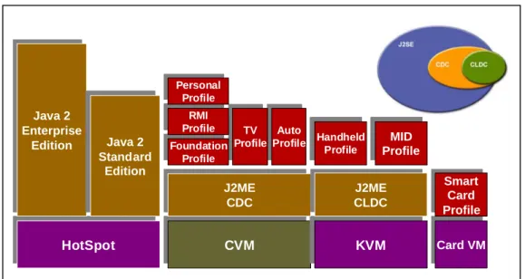
Figure 1 Java platform, micro edition (Java ME). ...2
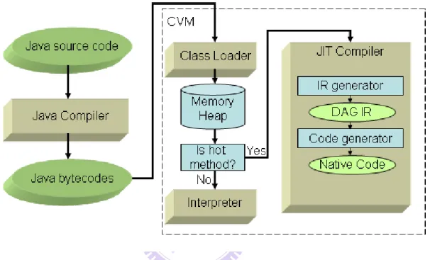
Figure 2 Overview of Java system architecture in CVM...3
Figure 3 Framework of code generation system... 11
Figure 4 Framework of local code analyzer and pattern-based peephole optimizer....12
Figure 5 Optimizer overview in CVM...13
Figure 6 Framework of pattern-based peephole optimizer. ...23
Figure 7 Total reductions by LCA in 4 phases...29
Figure 8 The improvement of CVM by revising emitter. ...38
Figure 9 shows the improvement by running benchmark in CVM. ...40
Figure 10 The improvement of CVM by revising BCOND rule node. ...40
Figure 11 The improvement of CVM by revising the semantic action...41
List of Tables
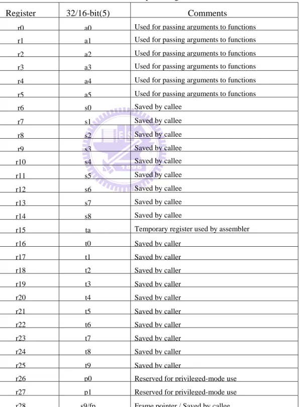
Table 1Andes General Purpose Registers ...4
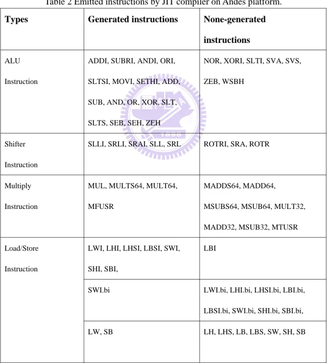
Table 2 Emitted instructions by JIT compiler on Andes platform. ...6
Table 3 The IR node information ...14
Table 4 Dead code elimination with redefine register value...16
Table 5 Dead code elimination with link instruction. ...16
Table 6 Dead code elimination with null sequence. ...17
Table 7 The redundant load/store elimination example. ...17
Table 8 The load copy optimization example. ...18
Table 9 The common Sub-expression example. ...19
Table 10 The target register and source register were consistent...19
Table 11 The copy propagation example with DCE. ...20
Table 12 The applicable instructions for constant propagation and constant folding..21
Table 13 The constant propagation example...22
Table 14 The algorithm of recurrence peephole optimizer. ...26
Table 15 Benchmark and its programs...27
Table 16 Dead code elimination and redundant load store elimination results. ...27
Table 17 Remove by DCE and RLSE...28
Table 18 Supporting type process and its effeteness with DCE and RLSE. ...28
Table 19 Reduce testing in 3 phases and 4 phases...29
Table 20 Pattern of pre-decrement offset with load instruction immediately. ...30
Table 21 Pattern of conditional branch. ...31
Table 22 Pattern of common sub-expression elimination...32
Table 23 Some sample patterns used on Andes code and their respective gain. ...32
Table 24 BCOND_INT rule rewrite...34
Table 25 STRING_ICELL_CONST node and its semantic action...35
Table 26 Compare the code size with original CVM...37
Table 27 Number of instructions which replace with LMW...37
Table 28 Number of instructions which replace by revising BCOND rule node. ...39
Chapter 1 Introduction
Many existing compilers for embedded systems generate low-quality code since the compilers, which are usually ported from different platforms, cannot take full advantage of the special features of the new platforms [9]. There is a need for further optimizations for the code generated by the compiler.
In this paper, we describe a new approach for optimizing ported compilers. We ported the CDCHI Java virtual machine [1][5] (which includes a Java JIT compiler) to the Andes platform [6][7]. For improving the code generator in a Java JIT compiler, we propose a new method. We implemented a local code analyzer and a pattern-based peephole optimizer that can automatically analyze the code generated by the ported JIT compiler for the Andes platform and help identify patterns of instruction that can be reduced to more efficient ones. The patterns are then implemented as JCS (Java Code Select, a code generator generator) rules or are incorporated into the code emitter in the ported Java JIT compiler.
Because of the similarity of Andes and MIPS ISA, we start porting with the MIPS version of CVM. After finish porting work, we observed that the quality of the code generated by the ported JIT compiler can be improved. It did not make use of the special features provided by Andes ISA. On the other hand, since the Andes platform is still in the development stage, Andes people are eager for our feedback concerning the Andes ISA. These reasons motivate us to develop a tool to analyze code generated by the ported JIT compiler and identify patterns in the generated code that can be optimized.
1.1.1 CVM Overview
designed for the resource-constraints devices, such as consumer products and embedded devices, including smart phones, high-end personal digital assistants(PDA) and global positioning system(GPS)[1][2].
J2ME application environment includes both a configuration like CDC and a profile like the personal profile. A configuration provides the most basic set of libraries and virtual-machine features that must be present in each implementation of java ME environment. When coupled with one or more profiles, the CDC gives developers a solid java platform for creating applications for consumer products and embedded devices. Figure 1 shows J2ME family and its supporting products.
Figure 1 Java platform, micro edition (Java ME).
We use CDCHI virtual machine as our system platform. CVM is a micro edition of java virtual machine. The Figure 2 shows that how java program works in CVM. A java program is compiled to the bytecodes by java compiler at static time. The bytecodes is then executed by the CVM. The class loader is responsible for loading classes. Because the existence of class loader, the java virtual machine does not need
HotSpotHotSpot CVMCVM KVMKVM Card VMCard VM Java 2 Enterprise Edition Java 2 Enterprise Edition Java 2 Standard Edition Java 2 Standard Edition J2ME CDCJ2MECDC J2ME CLDCCLDCJ2ME Smart Card Profile Smart Card Profile Handheld Profile Handheld Profile MID ProfileProfileMID Auto
ProfileProfileAuto TV ProfileProfileTV Foundation Profile Foundation Profile RMI ProfileProfileRMI Personal Profile Personal
of the method. If the threshold is higher enough to compile, the CVM will compile the method and execute it in native code. Otherwise, the CVM will interpret bytecodes and execution the method directly without compile. Inside the JIT compiler, the bytecodes will cover to IR(or DAG). Then the JIT compiler will parse the IR(or DAG) and call the code generator to emit instructions.
Figure 2 Overview of Java system architecture in CVM.
The CDC-HI-Dynamic Compiler dynamically translates java bytecodes into native code. The compilation process is per-method, meaning that only single method in class is compiled at a time.
1.1.2 Andes ISA Features
We use Andes processor as our hardware platform. For Andes processor, In order to support optimal system performance, Andes processor provides a set of mixed-length (16/32 bits) instructions. The mixed-length instructions can be freely used in program and without penalty in execution times. The Andes ISA is a RISC-style and register based instructions. Andes support various data types, such as
32-bit instruction format. The Andes instructions can use thirty-two 32-bit general purpose registers (GPR) and four 32-bit user special registers (USR). The four 32-bit USR can be combined into two 64-bit register and used to store 32-bit multiplication results. The following table status the name and usage of general purpose registers [6].
Table 1Andes General Purpose Registers
Register 32/16-bit(5) Comments
r0 a0 Used for passing arguments to functions r1 a1 Used for passing arguments to functions r2 a2 Used for passing arguments to functions r3 a3 Used for passing arguments to functions r4 a4 Used for passing arguments to functions r5 a5 Used for passing arguments to functions r6 s0 Saved by callee r7 s1 Saved by callee r8 s2 Saved by callee r9 s3 Saved by callee r10 s4 Saved by callee r11 s5 Saved by callee r12 s6 Saved by callee r13 s7 Saved by callee r14 s8 Saved by callee
r15 ta Temporary register used by assembler r16 t0 Saved by caller r17 t1 Saved by caller r18 t2 Saved by caller r19 t3 Saved by caller r20 t4 Saved by caller r21 t5 Saved by caller r22 t6 Saved by caller r23 t7 Saved by caller r24 t8 Saved by caller r25 t9 Saved by caller
Register 32/16-bit(5) Comments
r29 gp Global pointer r30 lp Link pointer r31 sp Stack pointer
The register set of $a0-$a5 is used for passing argument to functions. The values of them are not preserved across function calls. $a5 is used to save return value if it is a fundamental data type and its size is 4-byte long or less. If any register of the register set of $s0-$s8 is modified within the called function, it must saved it in the stack frame before use and restore from the stack frame before returning from the function. The $ta register is a temporary register and used by assembler. The register set of $t0-t9 is temporary register and used for expression evaluations. The values of the register set are not preserved across the function calls. The register $p0 and $p1 are used by OS only. The register $fp is used to save frame pointer. The register $gp register is used as global pointer and context pointer. The register $lp is used to save return address of caller function and the register $sp is used as stack pointer. If the $lp or $sp is modified within the function call, it must saved in the stack frame before use and restore from the stack frame before returning from the function.[7]
1.2 Motivation
Because of the similarity of Andes and MIPS, we choose the MIPS version as our base platform while porting the Andes onto CDC-HI virtual machine. After the porting work, we observe that the utilization of Andes ISA is quite poor. For Andes, the processor is in development stage and hope to feedback useful information about the ISA. Those reasons impel us to develop the tools to analyzer code and
find out the patterns which can be optimized. The following table lists gather statistics of emission of the JIT compiler on Andes platform.
From the table, we can observe that Andes support various types for load/store instruction. The “.bi” form means “before increase”, so the base register will be update after the memory operation [6]. The instruction type of before increment doesn’t emit very frequently since the MIPS port doesn’t support this type of instructions.
Table 2 Emitted instructions by JIT compiler on Andes platform.
Types Generated instructions None-generated
instructions
ALU
Instruction
ADDI, SUBRI, ANDI, ORI,
SLTSI, MOVI, SETHI, ADD,
SUB, AND, OR, XOR, SLT,
SLTS, SEB, SEH, ZEH
NOR, XORI, SLTI, SVA, SVS,
ZEB, WSBH
Shifter
Instruction
SLLI, SRLI, SRAI, SLL, SRL ROTRI, SRA, ROTR
Multiply
Instruction
MUL, MULTS64, MULT64,
MFUSR
MADDS64, MADD64,
MSUBS64, MSUB64, MULT32,
MADD32, MSUB32, MTUSR
LWI, LHI, LHSI, LBSI, SWI,
SHI, SBI,
LBI
SWI.bi LWI.bi, LHI.bi, LHSI.bi, LBI.bi,
LBSI.bi, SWI.bi, SHI.bi, SBI.bi, Load/Store
Instruction
Types Generated instructions None-generated instructions
NONE LW.bi, LH.bi, LHS.bi, LB.bi,
LBS.bi, SW.bi, SH.bi, SB.bi,
Jump Instruction J, JAL, JR, RET, JRAL NONE
Branch Instruction BEQ, BNE, BEQZ, BNEZ, BGEZ, BLTZ, BLEZ, BGTZ
Load/Store multiple
word Instruction
NONE LWM, SMW
Branch with link
Instruction
NONE BGEZAL, BLTZAL,
Conditional Move
Instruction
NONE CMOVZ, CMOVN,
Another low utility instruction type is branch instruction. The JIT compiler only generates the equal or not equal format. Since Andes ISA supports more types of conditional branch instructions, so there should be the opportunities to improve the compilation systems.
Many processors support specific purpose instructions which equivalent to a sequence of more general instructions. Specific purpose instructions are often smaller or faster then the general ones. In Andes processor, the JIT compilers never emit the load/store multiple word instructions, branch with link instructions and conditional move instruction. Those instructions can divide into two or more instructions. That means, we have further chance to find such patterns and transfer them into the simplified ones.
1.3 Contribution
In this thesis, we collect numerous patterns in assembly code level by using local code analyzer and pattern-based peephole optimizer. We provide a new method to extension patterns and solve resource conflict problem by recursive way. We also present an experimental framework and design a number of experiments to discuss the effectiveness of each optimization process. We list the patterns we found and categorize them as the types of modified JCS or rewriting code emitters. We also demonstrate how to revise JCS and emitters to improve performance.
1.4 Thesis Organization
The rest of this paper is organized as follows. In Section 2, we briefly introduce the CDCHI virtual machine and the Andes architecture and review related work for peephole optimization. We describe, in Section 3, the optimization framework, the implementation details of the local code analyzer, and the pattern-based peephole optimizer. In Section 4, we discuss the effective patterns in the generated code and the results for the reduction of code sizes. Finally, we conclude the work in Section 5.
Chapter 2 Related Works
Reducing redundant code in RISC architecture has been a thoroughly studied issue. As reducing redundant code for the specific compilation system on embedded systems becomes more and more important, several optimizations in assembly code level has been proposed to achieve the goal of reduce code size and evaluate performance. In our research, we adopt Andes as our target processor and CVM as our compilation system. The impacts of ISA and code generation systems are discussed.
This chapter describes three major portions of optimization related work. The first one is the common optimization technology which is used in local code analyzer. The second one is peephole optimization which is used to find the continuous instructions and help us to improve the compilation system. The last one is the compilation systems which would be modified after finding the patterns from local code analyzer and pattern-based peephole analyzer.
2.1 Common Optimization Technology
An instruction is dead if it produces values that are never used on any executable path leading from the instruction [8]. Kennedy provides dead-code detection algorithm [17] . The algorithm crossed between those basic blocks and identified as dead code by using work list for it. Latter, Knoop presented a new aggressive algorithm for the optimal elimination of partially dead code [18].
Copy propagation is a transformation that, given an assignment between two variables, replace later as long as intervening instructions have not changed the value of both [8]. Constant folding refers to the evaluation at compile time of expression whose operands ate known to be constant [8].
2.2 Peephole Optimizer Technology
Peephole optimization has been studied since 1965 [10]. The success of a peephole optimizer depends on the time and space for recognizing redundant sequences of instructions. Davison and Fraser [12][13][13] introduced a machine-independent and retargetable peephole optimizer, which replaces adjacent instructions with an equivalent single instruction.
Peephole optimization introduced by Kessler [15] was, instead of hand-written, automatically generated from an architectural description and allowed optimizations across basic blocks. Using patterns matching for code optimization is still one of the most popular approaches [9][16]. Spinellis used string-pattern matching to find out patterns. A pattern is a regular expression. Recently, Kumar defined numerous finite automata to recognize patterns [9]. The finite automaton is good for recognizing patterns that are not adjacent. Kumar also provided a replacement algorithm for resolving optimization conflicts. In our research, we find patterns and resolve optimization conflicts in a recursive way.
2.3 CVM - Code Generation System
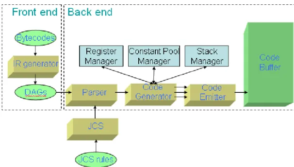
The JIT compilers have two phases to generate code. The first one is front end which translate the java bytecodes into intermediate representation (IR). The IR takes the form of DAG. In front end, it also handles other issues, such as verifier and security check and numerous optimizations on the IR. The other part is back end which handles IR parsing, generates code by semantic actions and work with register manager and emitter. The main task of back end processing is covering the IR into
The parser is generated by JCS which is constructing at build time. Most JCS rules have semantic actions, and this is what code generator takes place. The code generator sets some details or constraints before emit the instructions. Then, the code generator will call the emit functions and the instructions are actually emitted at this time. The code emitter exists at lowest layer of JIT compilers and responds to generate the instructions for the specific processor.[1][4]
Figure 3 Framework of code generation system
The other key components are register manager, constant pool manager and stack manager. The register manager is used to track the location of evaluated value. The locations can be either in the compiled frame, in the constant pools, or in a register. Each evaluated value is mapped to a resource managed by the register manager. The constant pool manager is used to manager 32 bits and 64 bits constants that are referenced by generated code. Although many constants can encode within the instruction, but large constant usually need to store in memory and load into register before use. The stack manager is used to manager method parameters pushed onto the java evaluation stack in compilation time [1][4].
Chapter 3 Optimizations
A series of peephole optimizations technique in assembly code level were presented in [9][10][11][12][13][14][15][16]. In the first section, we introduce function of optimizer in the CVM, followed by the detail of the optimizations in different purpose in section 3.2-3.3. Finally, the summary of the optimizations is given in the last section.
3.1 Framework of Optimizer
In this paper, we provide two tools to help evaluate performance and to identify patterns which can be optimized. According to optimizations operating on local code or adjacent instructions, we divide optimizations into two parts, as shown in Figure 4.
The first one, called local code analyzer (LCA), is implemented by some common compiler optimization technique within basic block. The second one, called pattern-based peephole optimizer, is based on recursive call to exhaustively finding patterns on adjacent instructions.
The input of local code analyzer and pattern-based peephole optimizer were native code (i.e. jitted code). We translate the native code into IR which is constructed of double linked list. Then we implement program optimization techniques and do manipulation on the IR.
3.1.1 Optimizer in CVM
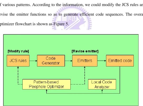
In order to evaluate the benefit of implementing online peephole optimizer, we use local code analyzer to assist in the analyzing work. Also, the local code analyzer would return contiguous instructions as base patterns in the pattern-based peephole optimizer. The pattern-based peephole optimizer returns the proportion and numbers of various patterns. According to the information, we could modify the JCS rules and revise the emitter functions so as to generate efficient code sequences. The overall optimizer flowchart is shown as Figure 5.
Figure 5 Optimizer overview in CVM
3.1.2 IR format
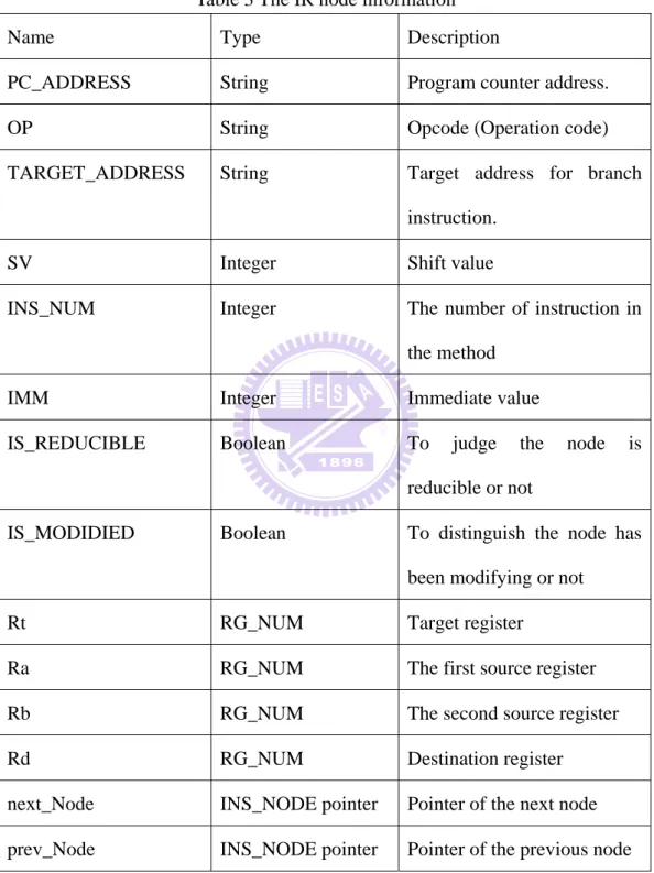
The IR we used is constructed of double linked list. Each IR node keeps a record of instruction information as shown in Table 3. The OP column is recorded of opcode
according to Andes ISA. Beside that, we also define “BBB” as basic block barrier to separate from basic block.
Table 3 The IR node information
Name Type Description
PC_ADDRESS String Program counter address.
OP String Opcode (Operation code)
TARGET_ADDRESS String Target address for branch
instruction.
SV Integer Shift value
INS_NUM Integer The number of instruction in
the method
IMM Integer Immediate value
IS_REDUCIBLE Boolean To judge the node is
reducible or not
IS_MODIDIED Boolean To distinguish the node has
been modifying or not
Rt RG_NUM Target register
Ra RG_NUM The first source register
Rb RG_NUM The second source register
Rd RG_NUM Destination register
next_Node INS_NODE pointer Pointer of the next node
3.2 Local Code Analyzer
Before discussing the local code analyzer, we define two terms first. If the value of a register will be updated after executing an instruction, we called the register a “producer register”. On the other hand, if the value of a register is used but not updated, we called the register a “consumer register”.
The optimization techniques which implemented in the local code analyzer will separate into three categories. The first one is the elimination of redundant instructions. Such optimization technology will reduce the code size. This type of technology will be introduced in 3.2.1-3.2.2. The second category is replaced with the more efficient instructions, such optimization technology will not reduce the code space, but will make improve on the computational speed, and such optimization technology will be introduced in 3.2.3. The last category is the supporting type optimization technology, which is used to help increase the opportunity to eliminating redundant code. This type of technology will be introduced in 3.2.4-3.2.6.
3.2.1 Dead Code Elimination
Dead code elimination is a common compiler optimization. It is used to reduce code size by removing instructions which does not affect the program. In the low-level optimization, we eliminated the instructions which define useless register value.
For the example (Table 4), we found that gp register is loaded a value from memory address of “s1+0”, and then redefine its value at the 4th instruction. The gp register didn’t used between 2nd and 3rd instructions. So, we can remove the first instruction.
Table 4 Dead code elimination with redefine register value. Before Dead Code Elimination
0xf77626f8 152: lwi $gp, [$s1+0]
0xf77626fc 156: sethi $a0, 33623
0xf7762700 160: ori $a0, $a0, 484
0xf7762704 164: lwi $gp, [$a0+0]
After Dead Code Elimination
0xf77626f8 152: lwi $gp, [$s1+0]
0xf77626fc 156: sethi $a0, 33623
0xf7762700 160: ori $a0, $a0, 484
0xf7762704 164: lwi $gp, [$a0+0]
Because the “jal” and “jral” opcode could update lp register value, so when implementing the dead code elimination algorithm, we should consider such situation. The Table 5 demonstrates the status.
Table 5 Dead code elimination with link instruction. Before Dead Code Elimination
0xf778c770 184: ori $lp, $lp, 2232
0xf778c774 188: seth $a2, 33442
0xf778c778 192: ori $a2, $a2, 2464
0xf778c77c 196: jal 0xf777800c
After Dead Code Elimination
0xf778c774 188: sethi $a2, 33442
Beside the situations of redefining register, we also regard the null operation instructions as dead code. Table 6 shows that the target register and the source register are both the same and the opcode is the moving instruction or adding a zero immediate, we can remove such instructions.
Table 6 Dead code elimination with null sequence. Before Dead Code Elimination
0xf77634ec 1060: addi $a0, $a0, 0
After Dead Code Elimination DELETE
3.2.2 Redundant Load/Store Elimination
The redundant load/store elimination is tried to find out useless load or store instruction. We record the target register, base register and the offset value as a node. Once the target register or base register has been modified, we remove the instruction from our table. If we match the other instruction which is equal to the target register, base register and immediate value in our table, we could consider that the instruction is a redundant instruction. The Table 7 is a redundant load/store elimination example.
Table 7 The redundant load/store elimination example.
0xf77620b8 48: swi $s1, [$fp-8]
0xf77620bc 52: lwi $s1, [$fp-8]
In the above example, we could obverse that the first instruction and the second instruction have the same target register, base register and offset, so we can remove the second instruction safely.
3.2.3 Load Copy Optimization
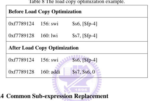
The optimization stage is combining with redundant load/store elimination process. The optimization only considers the base register and offset value. If the base register and offset value are the same between two instructions, we could revise the second one as a move instruction. Table 8 shows an example of load copy optimization.
Table 8 The load copy optimization example. Before Load Copy Optimization
0xf7789124 156: swi $s6, [$fp-4]
0xf7789128 160: lwi $s7, [$fp-4]
After Load Copy Optimization
0xf7789124 156: swi $s6, [$fp-4]
0xf7789128 160: addi $s7, $s6, 0
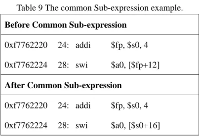
3.2.4 Common Sub-expression Replacement
Using common sub-expression could reduce the number of consumer register, and improve the opportunity of dead code elimination. When we encountered the opcode “addi”, we firstly judge whether the target register and source register are consistent. If they were inconsistent, we would record the target register, source register and immediate value.
As shown in Table 9, we could observe that the fp register is equal to sum of s0 register and immediate value ‘4’. In the second instruction, the fp register could replace as “s0+4”, and together with the offset 12, we can use “s0+16”. The replacement would reduce consumer register number, and indirectly enhance the
Table 9 The common Sub-expression example. Before Common Sub-expression
0xf7762220 24: addi $fp, $s0, 4
0xf7762224 28: swi $a0, [$fp+12]
After Common Sub-expression
0xf7762220 24: addi $fp, $s0, 4
0xf7762224 28: swi $a0, [$s0+16]
If the target register and source register were consistent, we would abandon the node since it may cause errors as the following example shown in Table 10.
Table 10 The target register and source register were consistent.
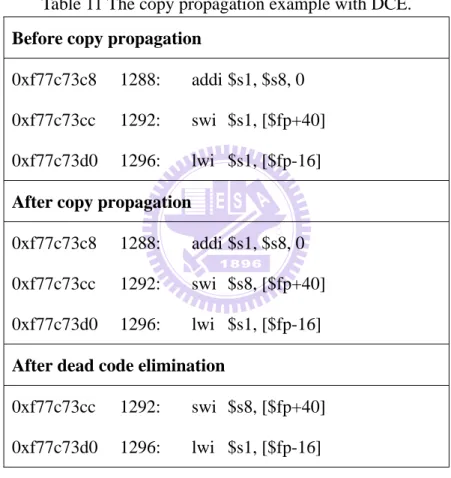
3.2.5 Copy Propagation
Using copy propagation could reduce the number of consumer register, but it’s different from common sub-expression since it only record the target register and source register and could apply to more cases. When we encountered the opcode “addi” and its immediate value was zero, we could record it into the table. Such instructions represent a moving action actually. Therefore, in a reasonable live range, when we encountered an instruction which its source register is the same as target
Before Common Sub-expression
0xf7762350 136: addi $s0, $s0, -4
0xf7762354 140: lwi $gp, [$s0+0]
After Common Sub-expression
0xf7762350 136: addi $s0, $s0, -4
register in our table, we could replace it.
The following example (Table 11) demonstrates that the copy propagation could reduce the usage of consumer register and improve elimination chance. In the first instruction, we record the s1 and s8 as target and source register. And then, in the second register, we could replace s1 as s8. In the third instruction, we found it was redefining s1 register value and the first instruction could be eliminated safely.
Table 11 The copy propagation example with DCE. Before copy propagation
0xf77c73c8 1288: addi $s1, $s8, 0
0xf77c73cc 1292: swi $s1, [$fp+40]
0xf77c73d0 1296: lwi $s1, [$fp-16]
After copy propagation
0xf77c73c8 1288: addi $s1, $s8, 0
0xf77c73cc 1292: swi $s8, [$fp+40]
0xf77c73d0 1296: lwi $s1, [$fp-16]
After dead code elimination
0xf77c73cc 1292: swi $s8, [$fp+40]
0xf77c73d0 1296: lwi $s1, [$fp-16]
3.2.6 Constant Propagation and Constant Folding
Constant Propagation process recorded the register which its value was known. If the opcode is “movi”, we push the target register and its value into table. And then apply it to the following instruction shown in Table 12.
register in our table. If the same, we could counting its real value and revise it as “movi” instruction.
The second column is the type of ALU instruction without an immediate value. If the second source code was the same as target register in the table, we could replace it with the type of supporting immediate format.
The last column is a set of memory access instruction which offset was register type. If the offset register was the same as target register in recorder, we could replace it as corresponding type which is supporting immediate offset.
Table 12 The applicable instructions for constant propagation and constant folding.
Constant Folding Arithmetic Propagation Memory Address Propagation
Before After Before After Before After
ADDI MOVI ADD ADDI LB LBI
SUBRI MOVI SUB SUBRI LBS LBSI
XORI MOVI XOR XORI LH LHI
ORI MOVI OR ORI LHS LHSI
ANDI MOVI AND ANDI LW LWI
SLL SLLI SB SBI
SRL SRLI SH SHI
SW SWI
All of three types above could reduce one consumer register, therefore increment the opportunity of redundant code indirectly. The following example (Table 13) demonstrated how constant propagation work. According to the first instruction, we could record the gp register as ‘0’. In the fourth instruction, we could replace gp register as ‘0’, and replace the opcode “addi” to “movi”.
Table 13 The constant propagation example. Before Constant Propagation
0xf77f38cc 76: movi $gp, 0
0xf77f38d0 80: swi $gp, [JFP_$fp-44]
0xf77f38d4 84: lwi $s1, [JFP_$fp+36]
0xf77f38d8 88: addi $s4, $gp, 0
After Constant Propagation
0xf77f38cc 76: movi $gp, 0
0xf77f38d0 80: swi $gp, [JFP_$fp-44]
0xf77f38d4 84: lwi $s1, [JFP_$fp+36]
0xf77f38d8 88: movi $s4, 0
3.3 Pattern-based Peephole Optimizer
The basic patterns for pattern-based peephole optimizer are collecting from local code analyzer. As result to recursive way, the pattern-based peephole optimizer can cover all optimization cases. This can be an efficient solution for resource conflict situations and need not extra phase to deal with resource conflict. In addition, in the matching process, we can check the modification flag of the IR node to distinguish the node is modified or not. If the node is modified and matched, we can regard it as a new extended pattern. The pattern extends as far as possible will help us to observe the JCS rules widely or the function call applied by the emitters. Using patterns to describe the pattern and matching with recursive way can reduce time to write similar patterns.
discussion (as shown in Figure 6). The first one is pattern matcher, which is generated by the pattern-matcher generator. The internal functions of pattern matcher will be called by pattern-based peephole optimizer and determine whether the instruction sequences is replaceable or not. The pattern matcher is introduced in 3.3.1.
The second part is pattern-matcher generator which is used to generate pattern matcher automatically. This part is introduced in 3.3.2. The third part cost function is implicit in the pattern matcher, which can be used to valuation the benefits of optimizing patterns and to obtain the best optimization steps. This part is introduced in 3.3.3. The latest one is recurrence peephole optimizer which is the main program in pattern-base peephole optimizer. Through the recursive way to finding extended pattern and return to the developers. This part is introduced in 3.3.4.
Figure 6 Framework of pattern-based peephole optimizer.
3.3.1 Pattern Matcher
be called by recurrence peephole optimizer. Pattern matcher has three major tasks. First, match patterns. If we find the matched pattern, we would record it into modification flag. Second, replacement instruction sequences. Once we match the pattern, we would replace instructions with efficient ones. If the instruction has been replaced before, that means, we find new extended pattern in the program. Finally, return the optimization gains. In the end of the function would calculate the benefits of optimization and return the gains. If no matching process invoke, the function would return zero.
3.3.2 Pattern-Matcher Generator
The input of pattern-matcher generator is instruction descriptor which is base on the canonical form [19]. We support three type of description. They are registers descriptor, immediate descriptor and address descriptor. Those descriptors have its own ID with the order of increment number. The immediate descriptor not only supports the constant type (ex.c0, c1), but also the real immediate values (ex. 0, 1). In the process of generating pattern matcher, if the descriptor position has been defined, we must check the correctness between the current descriptor and defined descriptor. If not, record current position into table.
The first line of pattern descriptor should be total pattern number T, and with T continuous patterns. The format of each pattern is shown below.
z Pattern ID number
z Number of reduced instructions z Number of replaced instructions z Input/Output instruction length
The function name format is the name of the first opcode with a pattern ID number (ex. lwi_0). The position number is the number of each instruction position from zero. If the operand is the register descriptor, we would check the register is defined or not in the table. If defined, we should comparison current node register with defined register and output the comparison code into pattern matcher. If not defined, we would record current position and register type(Rt, Ra or Rb) into table. If the operand is the address descriptor, we check the definition of position in the address table. If defined, we generate the comparison instruction into pattern matcher. If not defined, we record current position into the address table. If the operand is the constant descriptor, it has the same action as above. In addition, we support the summation function for the constant descriptor.
3.3.3 Cost Function
The concept of the cost function is implicit in the internal pattern matcher. Calculating the benefits of pattern replacement through the definition of reduce gain and replace gain each time. The calculating value would be used to find the best solution in the recurrence optimizer.
3.3.4 Recurrence Peephole Optimizer
The optimization of recurrence peephole optimizer is based on continuous sequences. We would make a copy before doing optimization so that facilitate to compare the benefit of applying different patterns. Every time matching successfully, we would call recurrence function again till no pattern bas been matched. When the recurrence optimization process has been done, we should record the max gain and return it. The way of using recursive call could achieve the objective of exhaustive matching. The algorithm of recurrence peephole optimizer is shown in Table 14.
Table 14 The algorithm of recurrence peephole optimizer. Function RPO
Backup Instructions
Max_Gain = 0;
Local_Gain =0;
While Current_Node not equal to End_Node
For each patterns i
Local_Gain = Pattern_function[i] (Current_Node)
if(L_Gain != 0)
L_Gain = L_Gain + RPO End if
Max_Gain = Local_Gain > Max_Gain ? Local_Gain : Max_Gain
Local_Gain = 0;
End for
Current_Node = Current_Node ->next_Node;
End while
Restore Instructions
return Max_Gain;
End Function
3.4 Summary
The local code analyzer is helpful to evaluating the benefits of all kinds of local optimization technique. The local code analyzer is also good for us to find adjacent sequences as basic pattern in the pattern-based peephole optimizer. We combine the process of mating patterns, replace pattern and finding the optimize solution into one stage. The recurrence peephole optimizer reduces the phase of solving resource conflicts. It’s quite helpful to reduce the space overhead in traditional way.
Chapter 4 Results and Analyses
4.1 Experimental Framework
For benchmarking, we selected fifteen programs from CLDC evaluation kit, Embedded Caffeine Mark [21] and Grinder Bench [20] (see Table 15). We ran all programs on Linux 2.6 on an Andes development board AG101. The clock rate of the on-board processor is 400 MHz.
The local code analyzer gathers statistics of the number of eliminated instructions and examines the patterns found in the benchmarks. Then these patterns are incorporated into our ported JIT compiler. Performance improvement is then measured.
Table 15 Benchmark and its programs. Benchmark Programs
CLDC evaluation kit Richards, DeltaBlue, ImageProc, Queen
Embedded Caffeine Mark Sieve, Loop, Logic, String, Method, Float
Grinder Bench Chess, Crypto, kXML, Parallel, PNG
4.2 Local Code Analyzer
The main reduction from local code analyzer is dead code elimination (DCE) and redundant load/store elimination (RLSE). So we test it separately at first.
Table 16 Dead code elimination and redundant load store elimination results.
Optimization Process Reduce number Reduce percentage
Dead Code Elimination 634 0.55%
Redundant Load/Store Elimination 366 0.31%
In one phase testing, the total reduce instruction is 1000 instructions. Then we combine those two optimization process and totally reduce 976 instructions, not 1000 instructions. This is because that redundant load/store instruction sometimes can regard as dead code. The following table demonstrates this situation.
Table 17 Remove by DCE and RLSE
lwi $s8, [$gp+20]
lwi $s5, [$fp-44]
lwi $s8, [$gp+20]
Then we consider the supporting type process, and observe the effeteness with DCE and RLSE. For dead code elimination, copy propagation given the most improvement, and for redundant load/store, common sub-expression improves the most.
Table 18 Supporting type process and its effeteness with DCE and RLSE.
First phase / Second Phase DCE RLSE
Ordinals 634 366
Copy Propagation 664 372
Constant Propagation 650 366
Common Sub-expression 657 383
Then we test our optimization process by brute force in three phases and four phases. Although it did really improve the number of reductive instructions, but in five phases, the optimization did not improve too much. So we did not consider the
Table 19 Reduce testing in 3 phases and 4 phases.
Phase Order Reduce instructions Reduce Percentage
1. RLSE 2. Copy propagation 3. DCE 1008 0.87% 1. RLSE 2. DCE 3. Copy propagation 4. DCE 1123 0.97%
The follow figure show the total reduction for each bench mark. The overall improvement is 0.98 % in four phases. The chess program improves the most. It total reduces 1.6% instructions.
Reduce % 0 0.5 1 1.5 2 strin g sieve metho d
loop logic float queen richa rds deltab lue imag epro c chess crypto kxm l png para llel Total Reduce %
Figure 7 Total reductions by LCA in 4 phases.
4.3 Patterns and Modifications
In our research, we discover some patterns are emitted very frequently and can reduce to the efficient ones. They are common sub-expressions, conditional branches and instructions which can place with “lmw/smw”. Those patterns can
implementing delay emitting.
Modify JCS could cover most cases occurring in our patterns with lower penalty. We define new JCS rules with lower cost and JCS tool will select the lowest ones and generate efficient code generator. Generally, we need rewrite our emitter so that can cooperate with new code generator. Another way to improve our JIT compiler is implementing delay emitting. This approach is easy to implement and can cover all patterns, but go with higher penalty. Most of the time, the high frequency pattern is generated within semantic action or emitter function. So we can make pattern implemented as a JCS rule by providing new rule and rewriting emitter. The pattern with lower frequency often generated from different rules and emitter. Although we can implement it by using delay emitting, but it’s not cost efficient and is not worth enough to implement.
4.3.1 Patterns
The most frequent pattern is pre-decrement offset and load instruction type. The pattern occurs when the function is going to return and load its return value from stack frame. CVM emit such instruction to do manual pre-decrement. This instruction pair can rewrite as “lmw” instruction format. The following figure demonstrates such situation.
Table 20 Pattern of pre-decrement offset with load instruction immediately. Oringinal pattern
addi $s0, $s0, -4
The other common patterns are conditional branch instructions. Those patterns can replace “slt/slts” instruction with “slti/sltsi” instruction. This pattern is emitted according to the “BCOND_INT” rules. The rule node is binary type. It forces its left child node must be register and compare with its right child node. Hence, in the follow example, we can see that the $ta is assigned by a constant 6 and compare with s6 register. We can exchange the child node order of the rule and provide a swap condition as a new semantic action. Then, rewrite the related emitter to support new code generator.
Table 21 Pattern of conditional branch. Oringinal pattern
movi $ta, 6
slt $ta, $ta, $s6
bnez $ta, 0xf77aba74
Revise pattern
slti $ta, $s6, 7
beqz $ta, 0xf77aba74
The third pattern is a special case of setting register as address of icell. A CVMObjectICell is a construct for holding a pointer to an object [3]. In Table 22, the value of $s8 register in revise pattern is different from the original pattern. From our observation, the $s8 register here is used as a pointer which point to a string object and the value won’t be reference in the future. Hence, we can rewrite it as the new one without considering the correctness of the register value.
Table 22 Pattern of common sub-expression elimination. Oringinal pattern sethi $s8, 33748 ori $s8, $s8, 2704 lwi $gp, [$s8+0] Revise pattern sethi $s8, 33748 lwi $gp, [$s8+2704]
The following table shows some of the patterns for Andes native code which collected from local code analyzer and recurrence peephole optimizer. We include here results for improvement in instruction number.
Table 23 Some sample patterns used on Andes code and their respective gain.
Original Patterns New Patterns Gain in number
of instructions Frequency (total 114835 instructions) addi r0, r0, -4 lwi r1, [r0+0] lmw.adm r1, [r0], r1 , DELETE 1 1793 movi r0, c0 slt r1, r0, r2 bnez r1, a0 DELETE slti r1, r2, c0 + 1 beqz r1, a0 1 1069 movi r0, c0 slts r1, r0, r2 beqz r1, a0 DELETE sltsi r1, r2, c0 + 1 bnez r1, a0 1 83 movi r0, c0 slts r1, r0, r2 bnez r1, a0 DELETE sltsi r1, r2, c0 + 1 beqz r1, a0 1 59 movi r0, 0 j a0 1 17
bnez r0, a0 DELETE movi r0, 1 bnez r0, a0 j a0 DELETE 1 1 sethi r0, c0 ori r0, c1 lwi r1, [r0+0] DELETE sethi r0, c0 lwi r1, [r0+c1] 1 313 lwi r0, r1, c0 lwi r0, r2, c1 DELETE lwi r0, r2, c1 1 178 addi r0, r1, c0 addi r0, r2, c1 DELETE addi, r0, r2, c1 1 74 swi r0, r1, c0 lwi r0, r1, c0 swi r0, r1, c0 DELETE 1 55 addi r0, r0, 0 DELETE 1 53 lwi r0, r1, c0 swi r0, r1, c0 lwi r0, r1, c0 DELETE 1 11 lwi r0, r1, c0 lwi r0, r1, c0 lwi r0, r1, c0 DELETE 1 6 swi r0, r1, c0 swi r0, r1, c0 swi r0, r1, c0 DELETE 1 2 movi r0, 0 movi r1, 0 swi r0, [r2+c0] swi r1, [r2+c1] movi r0, 0 movi r1, 0 swi r0, [r2+c2] swi r1, [r2+c3] movi r0, 0 swi r0, [r2+c4] movi r0, 0 DELETE swi r0, [r2+c0] swi r0, [r2+c1] DELETE DELETE swi r0, [r2+c2] swi r0, [r2+c3] DELETE swi r0, [r2+c4] 4 5 lwi r1, [r0+0] addi r0, r0, c0 lwi.bi r1, [r0], c0 DELETE 1 24
4.3.2 Rewrite Emitters
The emitter function which emits pre-decrement and load instructions can be replaced with an “lmw” instruction. We modify the emitter to generate “lmw” instruction. The “lmw” instruction allows before/after and increment/decrement form.
We also can determine to modify the base register or not. In the pre-decrement case, the instruction subtracts 4 from the value of base register and followed a load instruction with zero offset. We revise it to generate a “lwm” instruction whose target register and source registers are the same and use “adm” form. The “adm” means after, decrement and modify. The base register will decrement first and regard as a base register. Finally, the base register will be update after execution.
4.3.3 Modify JCS Rules
BCOND_INT
The following JCS rule generates conditional branch instructions. Its left child node is register type so that the emitter always generates unnecessary move instructions. Hence, we rewrite it as the new one. The new rule allows its left child node as constant type. Beside that, we also need to reverse its conditional flag by providing a “swapcompare32cc” function. This function helps to reverse conditional flag when the BCOND rule node tends to emit “less equal”, “great equal”, “less then” or “great then” instructions.
Table 24 BCOND_INT rule rewrite. Original rule
root: BCOND_INT reg32 aluRhs : 20 : : : :
compare32cc(con, $$, CVMCPU_CMP_OPCODE); Revise rule
root: BCOND_INT ConstOperand reg32 : 20 : : : :
swapcompare32cc(con, $$, CVMCPU_CMP_OPCODE);
structure of icell and load string object from the pointer. The original rule set string pointer directly by emitting “sethi” and “ori” instructions. Then the semantic action of the rule calls memory related emitter to emit “lwi” instruction. We revise this rule to emit “sethi” and “lwi” instructions. The low part of address is combined with load instruction offset. Hence, we can reduce one instruction when the rule was applied.
Table 25 STRING_ICELL_CONST node and its semantic action. Original rule reg32: STRING_ICELL_CONST : 20 : : : : { CVMRMResource* stringICellResource; CVMUint32 stringICellReg; CVMRMResource* stringObjectResource = CVMRMgetResource(CVMRM_INT_REGS(con), GET_REGISTER_GOALS, 1); CVMUint32 stringObjectReg = CVMRMgetRegisterNumber(stringObjectResource);
CVMStringICell* stringICell = CVMJITirnodeGetConstantAddr($$)->stringICell;
CVMJITsetSymbolName((con, "StringICell"));
stringICellResource =
CVMRMgetResourceForConstant32(CVMRM_INT_REGS(con), CVMRM_ANY_SET, CVMRM_EMPTY_SET, (CVMUint32)stringICell);
stringICellReg = CVMRMgetRegisterNumber(stringICellResource);
CVMJITaddCodegenComment((con, "StringObject from StringICell"));
CVMCPUemitMemoryReferenceImmediate(con,CVMCPU_LDR32_OPCODE, stringObjectReg,stringICellReg, 0);
CVMRMoccupyAndUnpinResource(CVMRM_INT_REGS(con),
pushResource(con, stringObjectResource); CVMRMrelinquishResource(CVMRM_INT_REGS(con), stringICellResource);}; Revise rule reg32: STRING_ICELL_CONST : 15 : : : : { CVMRMResource* stringICellBaseResource; CVMUint32 stringICellBaseReg; CVMRMResource* stringObjectResource = CVMRMgetResource(CVMRM_INT_REGS(con), GET_REGISTER_GOALS, 1); CVMUint32 stringObjectReg = CVMRMgetRegisterNumber(stringObjectResource);
CVMStringICell* stringICell = CVMJITirnodeGetConstantAddr($$)->stringICell;
CVMJITaddCodegenComment((con, "Set high 20bit of StringICell"));
stringICellBaseResource =
CVMRMgetResource(CVMRM_INT_REGS(con),CVMRM_ANY_SET,
CVMRM_EMPTY_SET,1);
stringICellBaseReg = CVMRMgetRegisterNumber(stringICellBaseResource);
CVMNDSemitSETHI(con, stringICellBaseReg, ((CVMUint32)stringICell));
CVMJITaddCodegenComment((con, "StringObject from StringICell"));
CVMCPUemitMemoryReferenceImmediate(con, CVMCPU_LDR32_OPCODE, stringObjectReg, stringICellBaseReg, ((CVMUint32)stringICell)&0xfff);
CVMRMoccupyAndUnpinResource(CVMRM_INT_REGS(con),
stringObjectResource, $$);
pushResource(con, stringObjectResource);
4.3.4 Benchmarks
We run all programs with modified emitter and JCS rules separately. The complied CDCHI virtual machine is listed below with its code size (in Table 26). The code size of CVM doesn’t increase too much after revising.
Table 26 Compare the code size with original CVM.
Name Program Size
CVM Original version 4173071
Revise emitter 4173103
Revise JCS(1) – BCOND 4173394
Revise JCS(2) – STRING_ICELL 4173099
CVM All 4173484
For the “lmw” patters, we gather statistics for the number of replaceable instructions as shown in Table 27. For overall program, after applying this pattern, it reduces 1793 instructions which occupy 1.56% of all programs.
Table 27 Number of instructions which replace with LMW.
Program Name Instructions Reduce Instructions Percentage
Richards 22524 492 2.18 DeltaBlue 11828 205 1.73 ImageProc 1723 16 0.92 Queen 691 4 0.58 Sieve 330 8 2.42 Loop 346 8 2.31 Logic 357 0 0
String 1424 41 2.88 Method 2791 55 1.97 Float 348 0 0 Chess 18321 218 1.19 Crypto 16516 194 1.17 kXML 24264 435 1.79 Parallel 5420 47 0.86 PNG 7952 70 0.88 Total 114835 1793 1.56
We implement the pattern by revising emitter. Then we run all programs in the revise version. Figure 8 shows the improvement by running benchmark in CVM. We see an average performance improvement of 0.76 %. The kXML program improves the most. This is because that kXML program runs with the longest time, so it improves its performance obviously. We can improve the performance of most of all programs. This is because that we don’t cause many penalties from revising emitter.
-1 0 1 2 3 4 5 Richa rds Delta Blue Imag eProc Que en
Sieve Loop Logic Strin g Meth od Float Che ss Crypt o kXM L Parra llel PNG Total
instructions. The reduced instructions occupy 1.08% of all programs.
Table 28 Number of instructions which replace by revising BCOND rule node.
Program Name Instructions Reduce Instructions Percentage
Richards 22524 57 0.25 DeltaBlue 11828 28 0.24 ImageProc 1723 22 1.28 Queen 691 17 2.46 Sieve 330 3 0.90 Loop 346 2 0.58 Logic 357 0 0.00 String 1424 1 0.07 Method 2791 0 0.00 Float 348 15 4.31 Chess 18321 512 2.79 Crypto 16516 212 1.28 kXML 24264 130 0.54 Parallel 5420 23 0.42 PNG 7952 215 2.70 Total 114835 1237 1.08
-2 -1 0 1 2 3 4 Rich ards Delta Blue Imag ePro c Quee n Siev e Loop Logic Strin g Meth od Floa t Ches s Cryp to kXM L Parra llel PNG Total
Figure 9 shows the improvement by running benchmark in CVM.
We see an average performance improvement of 0.57 %. The kXML program improves the most. The float program is worse then the original CVM even thought it reduces 4.31% instructions after revising JCS rule and emitter. This is because that there has some penalties of revised emitter. In this pattern, we provide a swap condition function. This will cause some penalties for the patterns. The float program doesn’t run and spend a lot of time. So, for such program, we didn’t get any benefits after revising the code generation system.
-2 -1 0 1 2 3 4 Rich ards Delta Blue Imag ePro c Quee n Siev e Loop Logic Strin g Meth od Floa t Ches s Cryp to kXM L Parra llel PNG Total
Figure 10 The improvement of CVM by revising BCOND rule node.
For the common sub-expression pattern, we revise the semantic action of STRING_ICELL_CONST rule node. The STRING program and kXML program improve the most. This is because those program process a lot of string object and
-1 0 1 2 Rich ards Delta Blue Imag ePro c Quee n
Sieve Loop Logic Strin g
Meth od
Float Chess Crypto kXM
L Parra
llel
PNG Total
Figure 11 The improvement of CVM by revising the semantic action.
Finally, we combine all optimizable pattern together. The improvement of all programs is 0.89%. We reduce 2.91% instructions on average of all programs.
-2 -1 0 1 2 3 4 Rich ards DeltaB lue Imag ePro c Queen Siev e Loop Logic Strin g Meth od Floa t Chess Crypto kXML Parra llel PNG Total
Figure 12 The improvement of CVM with combine three patterns.
Table 29 Performance improvement and instruction reduction of all benchmark.
Benchmark Performance (%) Reduce Instruction (%)
CLDC evaluation kit 1.10 2.47
Embedded Caffeine Mark 0.42 2.54
Grinder Bench 1.17 3.16
Chapter 5 Conclusion and Future work
Rewriting JCS rules and the emitters could improve our system performance if the optimized method is hot enough. The added overhead in the emitter and the frequency of the patterns are the key points for improving performance. If a method does not run for a long time, the overhead will lower the performance.
In the process of identifying patterns, we observe that some instructions are difficult to use. Providing new instructions or revising the original ones may help reduce code size and improve performance. For example, the “conditional branch and link” instruction is never emitted by the JIT compiler since the type of instruction only supports the greater-or-equal and less-then condition. But for all programs, we see that the “bnez” and “beqz” instructions are emited the most often and are frequently followed with a “jal” instruction. If we can support “beqzal” and “bnezal” instructions, we can reduce the code size even more (estimated at 2.52% reduction in code size). We will gather statistics of the frequencies of instruction pairs to evaluate the benefits of the new instructions in the future.
References
[1]. Sun Microsystems. Java ME CDC, http://java.sun.com/javame/technology/cdc, 2008
[2]. Sun Microsystems. Java ME, http://java.sun.com/javame , 2008 [3]. Sun Microsystems. CDC HotSpot Implementation Dynamic Compiler
Architecture Guide, 2005.
[4]. Sun Microsystems. CDC Porting Guide, 2005.
[5]. Sun Microsystems. The CDC application management system, 2005. [6]. Andes Technology. Andes Instruction Set Architecture Specification, 2007. [7]. Andes Technology. Andes Programming Guide, June, 2007.
[8]. S. Muchnick, Advanced Compiler Design and Implementation. Morgan Kaufmann Publishers Inc, August 1997.
[9]. Rajeev Kumar, Amit Gupta, BS Pankaj, Mrinmoy Ghosh, and PP Chakrabarti.
Post-compilation optimization for multiple gains with pattern matching. ACM
SIGPLAN Notices 40 (12): 14 - 23, December 2005. ACM Press.
[10]. W. M. mcKeeman, Peephole optimization, Comm. ACM 8,7 (July 1965) , 443-444.
[11]. J. W. Davidson and C. W. Fraser. Automatic generation of peephole
optimizations (with retrospective). In Proceedings of Best of PLDI'1984.
104-111.
[12]. J. W. Davidson and C. W. Fraser. Eliminating redundant object code. In Ninth Annual ACM Symposium on Principles of Programming Languages, 128-32, 1982.
[13]. J. W. Davidson and C. W. Fraser. Code selection through object code
optimization. ACM Trans. Programming Languages and Systems, 6(4):505 - 526,
October 1984.
[14]. A. S. Tanenbaum, H. V. Staveren, and J. W. Stevenson. Using peephole
optimization on intermediate code. ACM Trans. Programming Languages and
Systems, 4(1): 21 - 36, January 1982.
[15]. P. B. Kessler. Discovering machine-specific code improvements. In Proc. Symp. Compiler Construction. ACM SIGPLAN Notices, 21(7): 249 - 254, July 1986. [16]. Diomidis Spinellis. Declarative peephole optimization using string pattern
matching. ACM SIGPLAN Notices, 34(2):47–51, February 1999.
[17]. K. Kennedy. A Survey of Data Flow Analysis Techniques. Program Flow Analysis. Prentice-Hall, Englewood Cliffs, New Jersey, 1981.
[18]. Jens Knoop, Oliver Rüthing, and Bernhard Steffen, Partial dead code
elimination, In Proceedings of the ACM SIGPLAN 1994 Conference on
Programming Language Design and Implementation, 147-158, Orlando, Florida, United States, June 20-24, 1994.
[19]. Sorav, Bansal, and Alex Aiken. “Automatic Generation of Peephole
Superoptimizers,” In Proceedings of the Conference on Architectural Support for
Programming Languages and Operating Systems, October, 2006 [20]. EEMBC. GrinderBench, http://www.grinderbench.com
[21]. Pendragon Software Corporation, Embedded CaffeineMark 3.0 benchmark,