76 IEEE ANTENNAS AND WIRELESS PROPAGATION LETTERS, VOL. 8, 2009
Optically Modulated Scatterer Technique
for Radiation Pattern Measurement
of Small Antennas and RFID Tags
Ray-Rong Lao, Member, IEEE, Wen-Tron Shay, Member, IEEE, Jimmy C. Hsu, and
Jenn-Hwan Tarng, Senior Member, IEEE
Abstract—The optically modulated scatterer (OMS) technique is
developed for the electromagnetic field distribution measurement with minimum disturbance to the field under test. In this letter, we present a novel method to measure the radiation pattern of unwired small dipole-like antennas such as radio frequency iden-tification (RFID) tag antennas by OMS technique. The radiation pattern could be measured by this technique without any metallic feeding wire that would disturb the field pattern. The variation of the radiation pattern caused by the materials attached to an RFID tag antenna could also be evaluated with this technique.
Index Terms—Optically modulated scatterer (OMS), radiation
pattern, radio frequency identification (RFID), tag antenna.
I. INTRODUCTION
T
HE optically modulated scatterer (OMS) technique is de-veloped for the electromagnetic field distribution mea-surement with minimum disturbance to the field under test [1]. Applications of such a technique had been successfully applied on the measurement of antenna patterns [2] and on the perfor-mance evaluation of microwave absorbers [3]. In most appli-cations, the OMS is used as a probe for field mapping. How-ever, by combining a photoconductive semiconductor switch (OMS switch) with a small dipole-like antenna, such as a radio frequency identification (RFID) tag antenna, the radiation pat-tern of this antenna can also be determined by this technique without any metallic cable with it. In most research on the de-sign of RFID tag antennas, metallic connecting wires, such as coaxial lines or coplanar strip lines to the tag antenna, are nec-essary for the radiation performance evaluation with conven-tional measurement technique [4]–[6]. These metallic cabling arrangements could introduce disturbance to the measured re-sult and thus degrade the measurement accuracy. In order to remove the disturbance caused by the feed cable, a wirelessManuscript received September 25, 2008; revised November 13, 2008. First published January 06, 2009; current version published April 17, 2009.
R.-R. Lao and W.-T. Shay are with the Department of Communication Engi-neering, National Chiao Tung University, Hsinchu 300, Taiwan, and also with the Center for Measurement Standards, Industrial Technology Research Insti-tute, Hsinchu 300, Taiwan (e-mail:[email protected]; [email protected]).
J. C. Hsu is with the Department of Electronic Engineering, National Tsing Hua University, Hsinchu 300, Taiwan, and also with the Center for Measure-ment Standards, Industrial Technology Research Institute, Hsinchu 300, Taiwan (e-mail: [email protected]).
J.-H. Tarng is with the Department of Communication Engineering, National Chiao Tung University, Hsinchu 300, Taiwan (e-mail: [email protected]).
Color versions of one or more of the figures in this letter are available online at http://ieeexplore.ieee.org.
Digital Object Identifier 10.1109/LAWP.2008.2012122
Fig. 1. System configuration of the monostatic OMS measurement system.
modulated backscattering technique has been proposed to mea-sure a planar inverted-F antenna (PIFA) for RFID applications [7]. This technique is achieved by connecting the antenna under test to an IC chip that consists of an oscillator-driven modulator whose power comes from the RF power transmitted by an illu-minating antenna.
In this letter, we propose a novel method to measure the ra-diation pattern of unwired small antennas by OMS technique [8]. The radiation pattern of a small dipole antenna is measured with the proposed OMS technique and is compared with the results simulated with CST Microwave Studio. Then, a com-mercial RFID tag antenna is measured with the same technique when it is attached to different consumer goods.
II. THEOMS MEASUREMENTSYSTEM
The OMS probe is composed of a small dipole and an OMS switch bonded on the central feeding gap of this dipole [9]. When the OMS probe is applied to electromagnetic field mea-surement, it is placed in the position where the field is to be determined. Fig. 1 shows the measurement configuration of a monostatic OMS system. The OMS probe is placed at a po-sition in front of the horn antenna where the electromagnetic field is to be determined. A 100-kHz modulated optical signal of 780 nm in wavelength is fed onto the OMS switch and mod-ulates the OMS probe. A portion of the electromagnetic field incident upon the OMS probe is scattered. Since the scattering cross section of the OMS probe is changed with the modulated optical signal, the scattered signal is also modulated at the same rate. By detecting the received signal with a coherent homodyne receiver, the magnitude and phase of the modulated scattering
LAO et al.: OMS TECHNIQUE FOR RADIATION PATTERN MEASUREMENT 77
signal from the OMS probe can be recovered. All the other non-modulated scattering signals, such as signals reflected from the environmental objects or from the walls, can be filtered out. Since there is no need for any electrical connection to be made to the OMS probe, perturbation of the field to be measured could be minimized.
When the OMS probe is moved around in the measurement area, both the magnitude and phase of the scattering signal change with the location of the OMS probe. By using the reci-procity theorem, it can be shown that the voltage detected by the homodyne receiver is proportional to the square of the electric field component lying parallel to the OMS probe at the probe position as
(1) where both and are represented by complex variables that contain magnitude and phase information, and is a com-plex function of the spherical coordinate angles and that characterizes the OMS probe in different orientations. For an OMS probe that is made of an omnidirectional short dipole and is moved within limited measurement region, could be considered a complex constant [1].
III. THEOMS TECHNIQUE FORANTENNAPATTERN
MEASUREMENT
For conventional antenna measurement techniques, to mea-sure the radiation pattern of an antenna, an RF metallic cable is necessary to be connected to the antenna under test. However, for some unwired small antennas such as RFID tag antennas, metallic cabling could introduce major disturbance to the mea-surement result.
The OMS technique is developed to determine the spatial electromagnetic field distribution. However, by combining the OMS switch with a small antenna, such as an RFID tag an-tenna, the radiation pattern of this antenna can also be deter-mined by this technique. As shown in the system in Fig. 1, the magnitude of the received scattered modulated signal indicates the variation in the strength of the field at the location of the OMS probe. If the incident electromagnetic wave on the probe is keeping with constant strength, then the magnitude of the re-ceived scattered modulated signal indicates the scattered per-formance of this probe and thus the radiation perper-formance of it. Now the electric field component in (1) becomes a complex constant, and represents the radiation characteristics of the OMS probe in different orientations and gives the radiation pattern of this probe. The OMS probe is placed at a fixed loca-tion in front of the horn antenna during the measurement. By rotating the OMS probe in different angles of or , the radi-ation pattern of the OMS probe can then be determined by the measured .
IV. RADIATIONPATTERNMEASUREMENTS OF ASMALL
DIPOLEANTENNA A. Measurement on a Small Dipole Antenna
In order to verify the feasibility of this OMS system for an-tenna pattern measurement, a small dipole anan-tenna working in the frequency band of 2.45 GHz is chosen and is bonded with an OMS switch at its central feeding gap, which makes it become an OMS dipole.
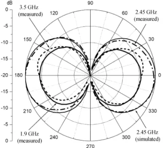
Fig. 2. The simulatedE-plane pattern of the dipole at 2.45 GHz and the mea-sured result at 1.9, 2.45, and 3.5 GHz.
This dipole is positioned on the -axis and is faced to the horn antenna as at a distance of 0.7 m. Measurement of the radiation pattern of this dipole was carried out by the OMS system. The power transmitted to the horn antenna is controlled to generate a field of about 25 V/m at the position where the dipole antenna is located for all the test frequencies. The sim-ulated -plane pattern at 2.45 GHz and the measured result at the frequencies of 1.9, 2.45, and 3.5 GHz are shown in Fig. 2. It shows good agreement between the simulated and measured results. Measurement results also show that the scattered field strength decreased as the frequencies moved away from the res-onant frequency. Similar results can also be obtained in the mea-sured -plane patterns.
B. Measurement on a Small Dipole Attached to a Plastic Slab
In the applications of RFID systems, the RFID tags are usu-ally attached to the surface of various commercial products. This situation would cause changes in the resonant frequency and in the radiation pattern of the tag. Here, the dipole is attached to a plastic dielectric slab made of polyethylene (PE), whose dielec-tric constant is about 2.5. The dimensions of this plastic slab are 75 52 35 mm. The CST simulated result indicates that the resonant frequency of the dipole is now changed to about 1.9 GHz. Figs. 3 and 4 show the simulated patterns at 2.45 GHz and the measured result at the frequencies of 1.9 and 2.45 GHz. Measured results show degradation in the radiation patterns at 2.45 GHz compared to that of 1.9 GHz due to the change of the resonant frequency.
V. RADIATIONPATTERNMEASUREMENTS OF ACOMMERCIAL
RFID TAG A. The Radiation Pattern of an RFID Tag
The proposed OMS radiation pattern measurement technique is applied to the measurement on the radiation performance of a commercial UHF RFID tag antenna. This RFID tag is designed to operate at the frequency range from 902 to 928 MHz and to be attached to the carton or to the surface of objects that are made of plastic material.
78 IEEE ANTENNAS AND WIRELESS PROPAGATION LETTERS, VOL. 8, 2009
Fig. 3. The simulatedE-plane pattern of the dipole attached to a plastic slab at 2.45 GHz and the measured result at 1.9 and 2.45 GHz.
Fig. 4. The simulatedH-plane pattern of the dipole attached to a plastic slab at 2.45 GHz and the measured result at 1.9 and 2.45 GHz.
In order to make this RFID tag become an OMS antenna, the RFID chip at the center of the tag is replaced by an OMS switch together with an optic fiber. The resonant frequency of an RFID tag antenna may change when we swap the RFID chip with an OMS switch of different impedance. However, these changes in resonant frequency can be estimated from the impedance values of the RFID chip and the OMS switch. This detuning effect could also be removed by using a matching circuit with OMS switch.
Since this RFID tag is designed to be attached to the plastic objects, measurements on the radiation pattern of this tag were carried out at the frequency of 915 MHz with:
1) the tag antenna alone, and
2) the tag antenna attached to a 10 50 3-mm plastic sheet made of polyvinylchloride (PVC) whose dielectric con-stant is about 2.8.
Fig. 5. The simulated and measuredE-plane patterns of an RFID tag at 915 MHz with and without a PVC sheet attached to it.
Fig. 6. (a) The RFID tag attached to a vitamin-filled plastic bottle. (b) The RFID tag attached to a liquid-filled plastic bottle.
The measured -plane patterns are shown in Fig. 5. As the purpose of the design of this tag, it shows better radiation per-formance when it is attached to a plastic material.
B. The Radiation Pattern of the RFID Tag With Consumer Goods
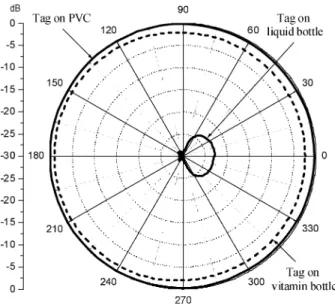
In order to evaluate the radiation performance of this RFID tag when it was attached to different consumer goods, measure-ments were carried out on this OMS tag with a vitamin-filled plastic bottle and a liquid-filled plastic bottle with curved shape as shown in Fig. 6. The tag antenna is positioned on the -axis, and the direction of the optic fiber is aligned with the -axis as . The measurement results are compared with the pattern when the tag is attached to a PVC sheet. Figs. 7 and 8 show the degradation in the radiation performance due to the attached objects. The scattered signal from the liquid-filled plastic bottle is much lower than those from a PVC sheet or a vitamin-filled plastic bottle and can hardly be detected. The enormous change and degradation in the radiation pattern is at-tributed to the curved shape where the tag is attached and the high loss of the liquid material the bottle contained. The result
LAO et al.: OMS TECHNIQUE FOR RADIATION PATTERN MEASUREMENT 79
Fig. 7. The measuredE-plane patterns at 915 MHz when the RFID tag is at-tached to a PVC sheet, to a vitamin-filled plastic bottle, and to a liquid-filled plastic bottle with curved shape.
Fig. 8. The measuredH-plane patterns at 915 MHz when the RFID tag is at-tached to a PVC sheet, to a vitamin-filled plastic bottle, and to a liquid-filled plastic bottle with curved shape.
implies that this tag may not be applicable to those containers that contain liquid materials.
VI. CONCLUSION
In this letter, the proposed OMS technique for radiation pat-tern measurement of small dipole-like antennas is demonstrated. This technique can be applied to the radiation performance mea-surement for the antennas with small dimensions or for un-wired antennas such as RFID tags. Since no electrical contact is
needed between the measurement instruments and the antenna under test, the field disturbance due to the metallic cabling could be eliminated. Meanwhile, since only the modulated scattered signal from the antenna under test is detected by this system, all the other nonmodulated signals—such as those reflected from the environmental objects, from the chamber walls, or from the material to which the tag is attached—can be filtered out.
Measurement results of a small dipole antenna and an RFID tag antenna show good agreement with the simulated data. In practice, commercial available software can simulate the tag and its radiation patterns of the tag with simple structured ma-terials. Nevertheless, when a tag is attached to a good material with complicated compositions or curved structures, measure-ment will be the best solution to find out the resulting radiation patterns. Measurements on the radiation patterns of an RFID tag affected by the materials to which it was attached can be carried out easily with this OMS technique. The proposed technique makes the measurement of the radiation performance of RFID tags without any metallic feeding wire possible and would be very useful for the designer to evaluate and optimize the perfor-mance of their RFID tags.
ACKNOWLEDGMENT
The authors would like to thank Mr. T. Chan and his col-leagues at Asia Smart Tag Co., Ltd., for kindly providing them with the RFID tags and the detailed information of these tags.
REFERENCES
[1] G. Hygate and J. F. Nye, “Measuring microwave fields directly with an optically modulated scatterer,” Meas. Sci. Technol., vol. 1, pp. 703–709, 1990.
[2] W. Liang, G. Hygate, J. F. Nye, D. G. Gentle, and R. J. Cook, “A probe for making near-field measurements with minimal disturbance: the optically modulated scatterer,” IEEE Trans. Antennas Propag., vol. 45, no. 5, pp. 772–780, May 1997.
[3] W. Liang, M. Alexander, B. Clark, and K. Pharaoh, “The use of an op-tically modulated scatterer to measure the performance of microwave electromagnetic wave absorber,” in Proc. 3rd Int. Symp. EMC, May 2002, pp. 404–407.
[4] C. T. Rodenbeck, “Planar miniature RFID antennas suitable for inte-gration with batterie,” IEEE Trans. Antennas Propag., vol. 54, no. 12, pp. 3700–3706, Dec. 2006.
[5] J. D. Griffin, G. D. Durgin, A. Haldi, and B. Kippelen, “RF tag antenna performance on various materials using radio link budgets,” IEEE
An-tennas Wireless Propag. Lett., vol. 5, pp. 247–250, 2006.
[6] K.-S. Min, G.-D. Park, and C.-K. Park, “Design for the miniaturized RFID tag antenna in 910 MHz band,” in Proc. TENCON 2007 – 2007
IEEE Region 10 Conf., Oct. 30-Nov. 2 2007, pp. 1–4.
[7] P. Pursula, M. Hirvonen, K. Jaakkola, and T. Varpula, “Antenna ef-fective aperture measurement with backscattering modulation,” IEEE
Trans. Antennas Propag., vol. 55, no. 10, pp. 2836–2843, Oct. 2007.
[8] R. R. Lao, M. J. Huang, W. T. Shay, and J. H. Tarng, “An un-intru-sive optically modulated scatterer technique for unwired small antenna measurement,” in Proc. Conf. Precision Electromagn. Meas. (CPEM
2008), CO, USA, Jun. 2008.
[9] R. R. Lao, W. Liang, W. T. Shay, R. P. Thompson, R. A. Dudley, O. Merckel, N. Ribiere-Tharaud, J.-C. Bolomey, and J. H. Tarng, “High sensitivity optically modulated scatterer for electromagnetic field mea-surement,” IEEE Trans. Instrum. Meas., vol. 56, no. 2, pp. 486–490, Apr. 2007.